Zeppelin Design Labs NOISETTE User manual


2
NOISETTE
OPTICAL THEREMIN
Assembly Manual
© 2023 ZEPPELIN DESIGN LABS. NO PART OF THIS DOCUMENT MAY BE REPRODUCED WITHOUT WRITTEN PERMISSION FROM THE AUTHOR. ZEPPELIN DESIGN LABS TAKES
NO RESPONSIBILITY FOR ANY DAMAGE OR HARM THAT MAY COME TO ANYONE OR ANYTHING THROUGH USING OR BUILDING THEIR PRODUCTS.
102023
INTRODUCTION ...................................................................................................... 3
HOW IT WORKS ................................................................................................ 4
WHAT YOU WILL NEED ............................................................................................ 5
TOOLS ............................................................................................................... 5
SUPPLIES ............................................................................................................ 5
WHAT’S IN THE BOX................................................................................................ 6
POPULATING THE PRINTED CIRCUIT BOARD............................................................... 8
USING YOUR NOISETTE ......................................................................................... 26
PLAYING YOUR NOISETTE................................................................................. 28
SCHEMATIC........................................................................................................... 29

3
INTRODUCTION
The Noisette is our take on a classic electronic musical instrument developed by the famous Russian
physicist Leon Theremin. The original circuit was stumbled upon by accident when Mr. Theremin was
developing a device that used radio waves to detect the density of different gases. To keep from having
to look at a meter while using this device, he added an audio amplifier and a speaker to this circuit as
to give an audible representation of the density of the gas being measured. In working on this circuit,
Leon found that his natural body capacitance altered some of its electrical parameters, causing the
audible pitch to rise and fall depending on how close he was to the circuit. This was such a novel and
unique discovery that he continued to develop the circuit and eventually turned it into the very first
electronic musical instrument that we all know as the Theremin, which also had the unique distinction
of being the first instrument that a person played without touching it.
Of course, this original circuit was made with vacuum tubes causing it to be big and bulky. Over the
years, with the advancement of technology, circuit designers have tweaked and modified the original
Theremin circuit to use transistors and other solid state components to reduce its size and cost. We
have taken this approach a step further by replacing the bulky capacitive sensing antennas with light
sensors, all while keeping the traditional circuit topology intact, along with the basic principle of being
a touchless instrument.
The Theremin is one of the world’s most unique instruments, being able to create spooky and other-
worldly sounds, all while not being touched! Even so, the popularity of the Theremin has fluctuated over
the years, but it has always had a passionate fan-base keeping it alive and in the public consciousness.
This passion for the Theremin has earned it a legendary status in the electronic music community around
the world. We here at Zeppelin Design Labs are very proud to be part of this legacy by bringing you
our modern take on this classic instrument. We sincerely hope you have as much fun building and
playing the Noisette as we did in designing it!

4
HOW IT WORKS
In general, Theremin circuits have two inputs: a pitch sensor, and a volume sensor. The pitch sensor
controls a circuit known as a voltage controlled oscillator (VCO), which generates the Theremin’s
audio signal. The volume sensor controls a circuit called a voltage controlled amplifier (VCA) which
alters the amplitude (or volume) of the audio signal that was generated by the VCO.
The Noisette circuit topology is basically the same as the original Theremin circuit. We are just
using a few modern components to obtain the same result. One of the main differences is instead of
vacuum tubes like in the original circuit, we are using integrated circuits (ICs, aka microchips) in the
VCO and VCA circuits.
The original Theremin circuit used capacitive sensitive antennas as its sensors. The Noisette uses light
detection sensors, known as LDRs (light dependent resistors) to determine the pitch and volume of
the audio. LDRs have a very large resistance across their pins in the dark, but the resistance drops
very low when light shines on them. For the pitch and volume sensors, we are using these LDRs in
a voltage divider circuit to obtain a variable voltage depending on how much light they detect. The
Noisette’s VCA also contains an LDR optocoupler. This optocoupler allows us to control the volume
of the audio through an LDR controlled by a light emitting diode (LED), the brightness of which is
controlled by the volume sensor circuit. The brighter the LED gets, the less resistance the LDR has,
causing the audio to get louder.
Figure 1 shows a block diagram of the Noisette circuit, to help visualize how it works.
VCA
VCO
PITCH
SENSOR
LDR
VOLUME
SENSOR
LDR
NOISETTE BLOCK DIAGRAM
LDR
LED
OPTO-
COUPLER
WAVE
SHAPE
MAX
VOLUME
HEADPHONE/LINE
OUT
SPEAKER
OUT
GAIN
SETTING
JUMPER
Figure 1: Noisette Block Diagram

5
WHAT YOU WILL NEED
Here’s everything you will need to build your Noisette Optical Theremin kit as shown below:
TOOLS
1. #2 Phillips screwdriver
2. Tiny (precision) flathead screwdriver for adjusting the trimmer potentiometers
3. Soldering iron (not a soldering gun, or a cold heat iron), good quality, 15-50 watt, with a good
medium or small-sized tip, conical or chisel shape. One with a temperature control and a stand
is best.*
4. Damp sponge to clean your soldering iron
5. Wire strippers*
6. Flush cutters or small diagonal cutters*
7. Clamp or vise to hold the printed circuit board while soldering (optional, but handy)
8. Solder sucker and/or solder braid (optional, but very handy if you have to remove or repair any
components!)
9. Ruler
10. Digital multimeter*
11. Needle nose pliers
12. Hot glue gun (as an alternative to super glue, see supplies)
SUPPLIES
1. Solder, 60/40 rosin core, the smaller diameter the better (we prefer .032” diameter). Make sure
it’s good quality. We prefer Kester brand, but most brands will work fine.
2. Super glue gel (thick CA glue), or hot a glue stick to be used with your hot glue gun, if you don’t
use super glue gel.
3. 9 volt battery (if not using a 9 volt wall adapter)
* Available from the Zeppelin Design Labs webstore.

6
WHAT’S IN THE BOX
Table 1: The Noisette Optical Theremin Bill of Materials (BOM) is a complete parts list of everything
that should be present in your kit, followed by photos of each part. Carefully go through the kit,
identifying every part. Please read about the proper handling of integrated circuits (ICs) in
paragraph 7 on page 18 before removing the circuit board from the silver static-protective bag.
Note that some of the components are difficult to tell apart. Compare them carefully with the photos.
Besides verifying that nothing is missing, this will acquaint you with the parts and their names. If
ANYTHING is missing, first double-check; we double-checked before sealing the bag at our lab! If
your kit, we will get replacement parts in the mail to you as soon as possible. If you lose or damage
anything, we will be glad to sell you replacements if we have them in stock. The unusual or custom
common parts, like resistors, capacitors, or screws, you may prefer to go to a local electronics or
hardware store.
Figure 2: What’s in the Box

7
Table 1: The Noisette Optical Theremin Bill of Materials (BOM)
Part # Description Notes Qty
CA-30-20 Speaker Grille Cover 1
ST-50-20 LDR Shield 2
PC-78-01 Noisette Circuit Board 1
ST-60-20 Nylon LED Standoff 1
DI-30-52 Green 5mm LED 2
SW-50-30 Pushbutton DPDT Switch 1
HD-40-40 1/8” TRS Audio Jack 1
HD-40-10 DC Power Jack 1
LS-30-32 1” 32 Ohm Loudspeaker 1
CP-10-08 Electrolytic Capacitor 16V 220uF C1, C2, C3 3
HE-20-01 Single Row Header 3 PIN 1
PT-30-30 Trim Potentiometer 100K 4
PT-10-10 9mm Potentiometer 100K 2
SN-30-10 LDR Sensor 3
CB-90-09 Heat Shrink Tubing (2mm x 42mm) 1
CB-90-15 Heat Shrink Tubing (5mm x 19mm) 1
HD-05-01 9V Battery Snap 1
ST-10-05 Hex Nylon Standoff M3.5x5 2
FA-60-38 Course Thread Screw Phillips Pan M2.5x5 2
FA-60-37 Machine Screw Phillips Pan M3x6 2
HE-60-02 Header Jumper 2 pin 1
SW-60-22 Red Switch Cap 1
CA-30-20 ST-50-20 PC-78-01 ST-60-20 DI-30-52
SW-50-30 HD-40-40 HD-40-10 LS-30-32 C1,C2,C3
HE-20-01 PT-30-30 PT-10-10 SN-30-10 CB-90-09

8
POPULATING THE PRINTED CIRCUIT BOARD
Your work space should be well-lit, well-ventilated, and disposable; that
is, don’t work on the nice dining room table! Work on a utility surface
that you can burn, drill, and scratch. A piece of ¼” tempered masonite,
or a chunk of MDF, makes an excellent surface if you don’t have a
utility work bench.
CAUTION: Solder fumes are not healthy for you. The fumes consist
of vaporized flux, which might irritate your nose and lungs. You should
work in a space where the air drifts away from you as you work, so fumes do
not rise straight into your face.
CAUTION: Solder residue usually contains lead, which is poisonous if you ingest it. Do not breathe
the fumes, do not eat the supplies, wash your hands after you handle solder, and sweep and wipe up
your work space after EVERY USE.
Your Noisette Optical Theremin contains one printed circuit board (PCB). All of the components will be
installed on the component side of the board, which is the side that has the part labels on it. The other
side of the board is called the solder side, which, as the name implies, is the side on which the legs
of the components are soldered. Proper technique for installing and soldering components to a circuit
board is demonstrated through several great resources on Instructables and Youtube under the search
“PCB soldering tutorial.”
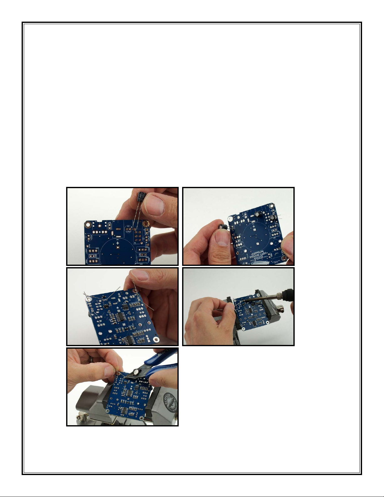
The general procedure consists of the following:
1. Install the part on the component side of the board, by threading the wire leads through the
appropriate holes in the board. For your convenience, the board has silk screen outlines indicating
where the components should be placed, along with text indicating the part number and the component
value.
2. Hold the component in place with your finger and turn the board over.
3. Gently bend the leads out at about 45 degrees to keep the component from falling out of its holes.
4. Install all of one type of component, bending each of the leads as they are installed.
CB-90-15 HD-05-01 ST-10-05 FA-60-38 FA-60-37
HE-60-02 SW-60-22
TIP: Empty the parts
of the kit into a bowl, NOT
onto the cluttered workbench, or
onto the living room carpet! This
will protect you from losing tiny
parts.

9
5. Flip the board over solder-side-up, and solder all of the components in one pass.
6. Clip the leads off with small diagonal cutters, right at the solder joint.
When soldering the components in this kit, try to keep them from getting too hot. Most components
have a temperature threshold that shouldn’t be exceeded. As a rule of thumb don’t keep your iron on
any leg longer than two seconds, and make sure the component stays cool enough to touch. If you find
you have a hard time keeping any component from getting too hot, just solder one leg at time and let
the part cool off before proceeding to the next leg. It’s a good idea to take your time with the assembly
process to ensure nothing goes wrong.
You will notice that we have already installed several components on the solder-side of the PCB.
These components are surface mounted, which are a little more difficult to solder than standard hole-
through components (like what you will be soldering on the board). Some of the surface mounted
components are sensitive to static electricity, meaning they can easily get damaged if they are exposed
to moderately high voltages. Unfortunately (or fortunately), humans are not sensitive to static electricity
at these levels; in fact, most people can’t even feel a static discharge less than around 1000 volts!
So it is easy to damage these components without even knowing it. Since these components are
already soldered to the circuit board, they are less likely to be damaged by static discharge but it is
still important to be mindful of these principles in handling them. When you handle the circuit board
(before you take it out of its anti-static bag, and throughout the assembly process), make sure you are
grounded, preferably by touching something grounded to the electrical mains like the metal chassis of
a plugged-in amplifier, or a refrigerator. At the very least you should touch a large conductive object
like a metal desk or a filing cabinet. With this information in mind, please proceed carefully.
HEAD-
PHONES
SPEAKER
ZEPPELIN
DESIGN LABS
NOISETTE
OPTICAL THEREMIN V1.2
Figure 3: Component Values and Locations

10
Let’s begin!
1. 220uF Electrolytic Capacitors (C1, C2, C3): The first thing we’ll install on your Noisette PCB are
the capacitors. There are three electrolytic capacitors (aka “caps”) in the Noisette. This type of
capacitor IS POLARIZED: there is a right direction and a wrong direction to install them. If you
get it wrong, they might burst. The white stripe on the case indicates the negative lead of the
cap. Notice that one of the leads is longer than the other. The long lead on the capacitor is the
positive lead (1).
STRIPE = NEGATIVE = SHORT LEAD = ROUND PAD
NO STRIPE = POSITIVE = LONG LEAD = SQUARE PAD
Make sure you orient this cap properly! For reference, the circuit board has a little plus sign(+)
on the positive pads. Bend out the leads, as in the picture (3), to keep the components from
falling out when you solder them. Flip the board over, solder and then snip all the leads close to
the solder joint (4,5).
1 2
3 4
5

11
2. Headers: Your kit includes one 3-pin header. The process we use to solder these headers is to
hold it in place with one finger, apply some solder to the tip of your iron, and then quickly tack
in one lead on the bottom of the board (7). Make sure you don’t hold down the pin that you are
trying to tack down because the pin will heat up and it might burn you. Also make sure the
bottom of the header is flush with the top of the board as this is done. Once one lead is held in
place with the solder, we can put the circuit board in our clamp and solder the rest of the leads
(8). Then we always re-solder the tacked-in lead to ensure it is making a good connection.
Once the header is installed, place the jumper on the 2 pins labeled SPEAKER (9).
6 7
8 9
3. Power Light (LED): Place one of the green LEDs in the LED standoff (set the other LED aside for
later). Feed the LED leads in through the open end of the standoff, and thread the leads through
the two small holes in the other end. The green plastic body of the LED should be up against the
open end of the standoff.

12
The LED is installed on the PCB in the spot marked LED, and it IS POLARIZED and must be
installed in the correct orientation. If you get it backwards, the light won’t work.
The long lead goes into the hole with the square pad, the short lead goes into the round pad
(12). Make sure the standoff is flush with the board and is standing straight up. Bend the leads
out on the bottom (as you did with the caps) (13); flip the board over and solder and clip the
leads (14,15).
10 11
12 13
14 15
4. Power Switch: Before you place the power switch on the board, push the little red button cap all
the way onto the switch (16). Press the switch snug to the board. Make sure the switch is sitting
level (parallel) with the top of the circuit board (17). Flip the board over and solder the leads
(18).
16 17

13
18
5. Power Jack: Press it snug to the board. Double check that it is sitting square to the front edge of
the board and flush to the top of the board before you solder it. Tack one pin of the jack into
place on the board while you hold it in (19). Once it’s tacked in place, finish soldering it to the
board (20).
19 20
6. Audio Jack: Install the audio jack at J1. Once again, use the tack-in method to install this jack
(21). Once the jack is held in place, finish soldering the rest of the pins (22). Remember to re-
flow the tacked in pin.
21 22
23

14
7. LDRs: As mentioned in the How It Works section, LDR stands for light dependent resistor and they
are used as the volume and pitch light sensors in the Noisette.
Your Noisette kit contains three LDRs. They have each been hand selected to have the correct
resistance range needed for their particular use in the Noisette. You will notice that one of these
LDRs has black dot on its backside. Set aside this LDR with the dot because it will be used for the
optocoupler, which we will assemble later. For now, we will be installing the two LDRs without
black dots.
In this application, the body of each LDR is held 21mm above the circuit board, which allows it
to reside inside the LDR shield. We will use a piece of 21mm tall heat shrink tubing to space the
LDR the proper distance above the PCB. Cut two pieces of 2mm heat shrink, 21mm in length.
Basically, just cut the ~42mm long piece of heat shrink in two equal pieces (24). They don’t have
to be exact, they can be off by +/- 1mm.
Place one piece of these pieces onto one leg of one of the LDRs (25). Install it in one of the LDR
locations (26); please don’t shrink the heat shrink, it is only being used as a spacer. Make sure
the LDR is standing up straight, perpendicular to the surface of the circuit board. Also make sure
the body of the LDR is sitting on top of the heat shrink. It helps to hold the LDR in place as you
tack one leg down (27). Solder both LDRs in place and clip their leads (28,29).
24 25
26 27
28 29

15
8. Trimmer Potentiometers: The Noisette contains four trimmer potentiometers (trim pots). VR1 – VR4
should fit into their locations with the adjustment screw located toward the right, as in the photo
(34).
Use the tack-in method to solder these trim pots in. Hold the pot in place with one finger, apply
some solder to the tip of your iron, and then quickly tack in one lead on the bottom of the board
(31,32). Make sure the bottom of the trim pot is flush with the top of the board. Remember to
re-solder the tacked in lead to make sure it is making a good connection. Solder all four trim pots
to the board, then snip the leads (33).
30 31
32 33
9. Potentiometers: Install the potentiometers (aka “pots”). Make sure they are all seated securely
and flush against the PCB; otherwise the completed board won’t fit properly into your Noisette’s
case. Double check that the shafts of the pots are all standing at 90 degrees (perpendicular) to
the board. When soldering do not use too much heat. If you cannot move quickly with your iron,
solder only one pin on each pot, sequentially. This will allow each pot to cool before you solder
its next pin. It is only necessary to solder the three small pins on each pot. The two large pins
help clip the pot to the PCB and it’s not necessary to solder them to the board (34,35,36,37).
34 35

16
36 37
10. Optocoupler: The optocoupler is part of the VCA circuit that controls the volume of the Noisette.
It consists of a light dependent resistor (LDR) and a light emitting diode (LED), both of which are
sealed inside a length of heat-shrink tubing. In a previous step we set aside the LDR with the
black dot on its backside. We will now use this dotted LDR in building the optocoupler. We will
first construct the optocoupler and then install it on the board.
a. Insert the green 5mm LED into the end of a piece of heat-shrink tubing. Proper placement of
the LED in the tube is important. Slide the LED into the tube until the back of the LED is about
5mm from the end. The LED just needs to be far enough into the tube so the end can be
pinched fully closed around the backside of the LED (38). This will keep as much ambient
light out of the tube as possible.
38 39

17
b. As you hold the LED in this position from the outside of the tube, carefully heat up the end of
the tube with your soldering iron until it closes around the LED leads (39,40). Once it has
stopped shrinking but while it is still very hot, use your pliers to pinch the shrunken tubing
closed around the leads to help seal the opening (41,42).
40 41
42
c. Slide the LDR into the other end of the heat-shrink tubing until it is touching the LED (43).
Rotate the LDR so that its leads are on the same plane as the LED leads (44).
43 44

18
d. As you hold the LDR from the outside of the heat-shrink, carefully heat this side of the tube
until it closes around the LDR leads (45,46). While it is still very hot, use your pliers to pinch
the end closed around the LDR leads (47).
45 46
47 48
Now that we’ve made the optocoupler, we can install it. The leads need to be bent 90
degrees, but it matters which way you bend them in order for them to fit on the board in the
proper orientation (remember, LEDs are polarized). If you put the opto in backwards the
volume sensor will not have any effect. Note the PCB graphics indicate where the LDR and
LED are intended to go. On your optocoupler, the LED has one long lead and one short
lead. The long lead of the LED goes into the hole with the square pad. Note which side of
the optocoupler needs to be up as you bend the leads down in order for it to fit into the
holes properly. Grip the leads with your needle nose pliers as shown (48) and bend them
down 90 degrees with your fingers (49). Bend the LDR’s leads in the same way, holding
with pliers and bending with your fingers (50).
49 50

19
e. Carefully install the optocoupler on the PCB. Double check to make sure the long LED lead is
in its correct hole -- with the square pad (51). Bend the leads out on the back, solder all four
leads and snip them (52).
51 52
11. Speaker: Place the speaker into its holes (53). The pin marked with a “+“ on the bottom of the
speaker goes into the hole marked “+.” Make sure it’s sitting flush to the top of the circuit board,
then solder the pins (54). Try not to use an excessive amount of heat on the pins; try not to let the
soldering iron tip linger on the pins longer than necessary.
53 54
55

20
12. Battery Snap: Before we install the battery snap we need to cut the leads to the correct length.
The leads need to be 72mm from the plastic snap. Measure with your ruler and cut them that
length (56). Then use your wire strippers to strip about 3mm (1/8”) of insulation off leads. (57)
56 57
Gently twist the tiny strands of copper wire together. Tin the ends of the wires with your soldering
iron (58), which means to add a tiny bit of solder to the wire to help hold the strands of wire
together. Make sure you don’t add too much solder otherwise the wire won’t fit into the circuit
board holes. Now solder the wires to the 9V port on the PCB (59,60). The red wire goes in the
square hole and the black wire goes in the round hole…DO NOT MIX THEM UP!
58 59
60 61
Table of contents
Other Zeppelin Design Labs Music Pedal manuals

Zeppelin Design Labs
Zeppelin Design Labs VPM-1 User manual

Zeppelin Design Labs
Zeppelin Design Labs VPM-1 User manual

Zeppelin Design Labs
Zeppelin Design Labs QUAVERATO MIDI MOD User manual

Zeppelin Design Labs
Zeppelin Design Labs QUAVERATO User manual

Zeppelin Design Labs
Zeppelin Design Labs ALTURA MKII Plus User manual

Zeppelin Design Labs
Zeppelin Design Labs QUAVERATO User manual