4
• Sharp pencil
• 12” Ruler
• Bar clamps, minimum 12” opening, two of them
• Utility knife or X-Acto knife or scissors
• Heat gun, or very hot hair dryer
• Soldering Iron, good quality, 15-50 watt
• Wet sponge or dry solder-cleaning pad
• Wire stripper / cutter, to strip 16-gauge wire
• Needle-nose pliers
• Some sort of clamp or fixture to hold parts while soldering. Your bar clamp might work.
2. Supplies
• Solder, rosin core for electronics
• Good quality wood glue such as TiteBond II or III
• Masking tape
• Good quality wood filler such as DAP Plastic Wood (optional)
• Sandpaper, either discs for your orbital, or sheets for your block: 60, 120, 220, 320
• Very small can of MinWax Dark Walnut Wood Finish (oil-based stain) or equal
• Small can of MinWax Wipe-On Poly, clear satin, or equal
• A small amount of flat black paint, spray or can
• Mineral spirits, for cleanup
• Clean rags
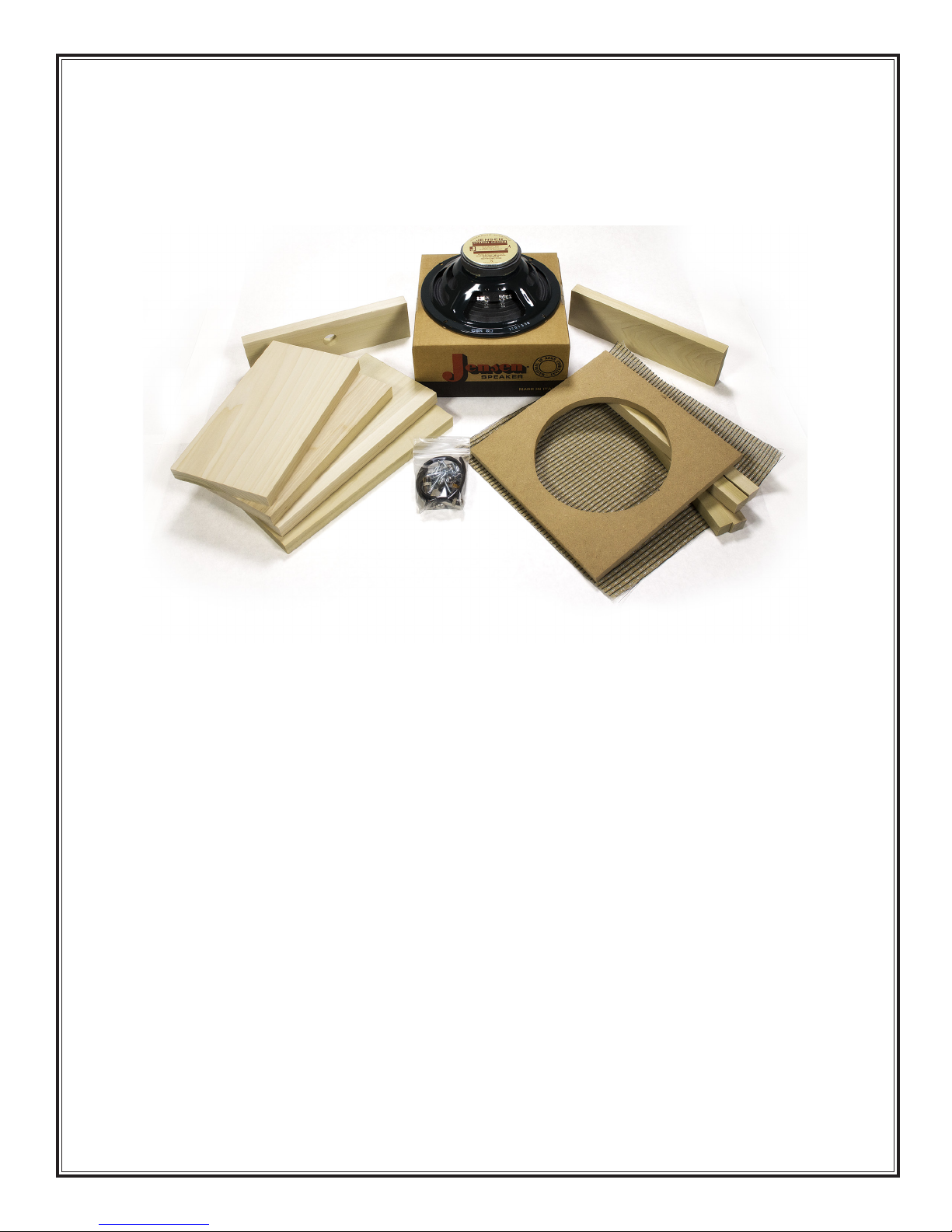
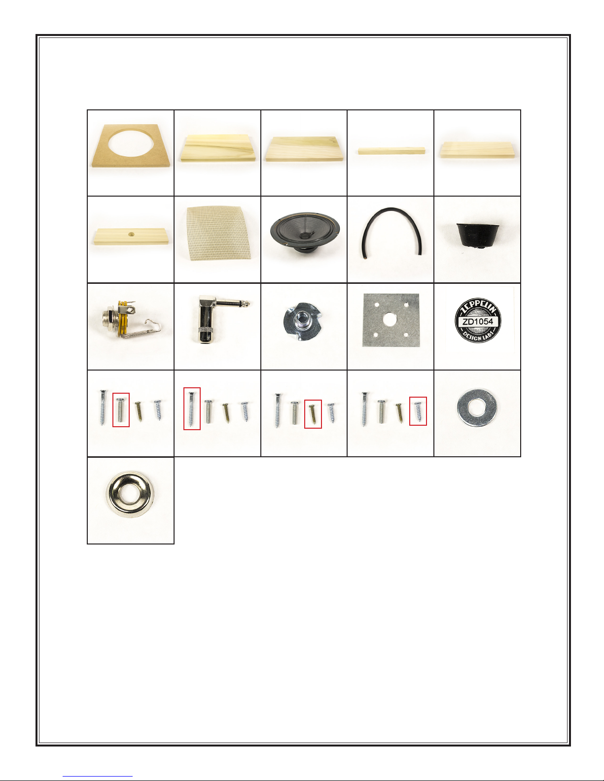
WHAT’S IN THE BOX
Table 1 on Page 6 shows a complete parts list of everything that
should be present in your kit, followed by nice color pictures
of each part. Print the parts list and carefully go through the
kit, identifying every part. Besides verifying that nothing is
missing, this will acquaint you with the parts and their names.
If ANYTHING is missing, or damaged beyond use, first double-
check: we double-checked before sealing the box at our lab! If it’s
still missing, EMAIL US right away at support@zeppelindesignlabs.
com. Include your serial number (on a little round sticker in the bag of hardware). If we are reasonably
convinced that we goofed and shorted your kit, we will get replacement parts in the mail ASAP. If you
lose or damage anything, we will be glad to sell you replacements. The unusual or custom components
can be ordered from us direct. For more common parts, like screws, you should just go to a local
hardware store.
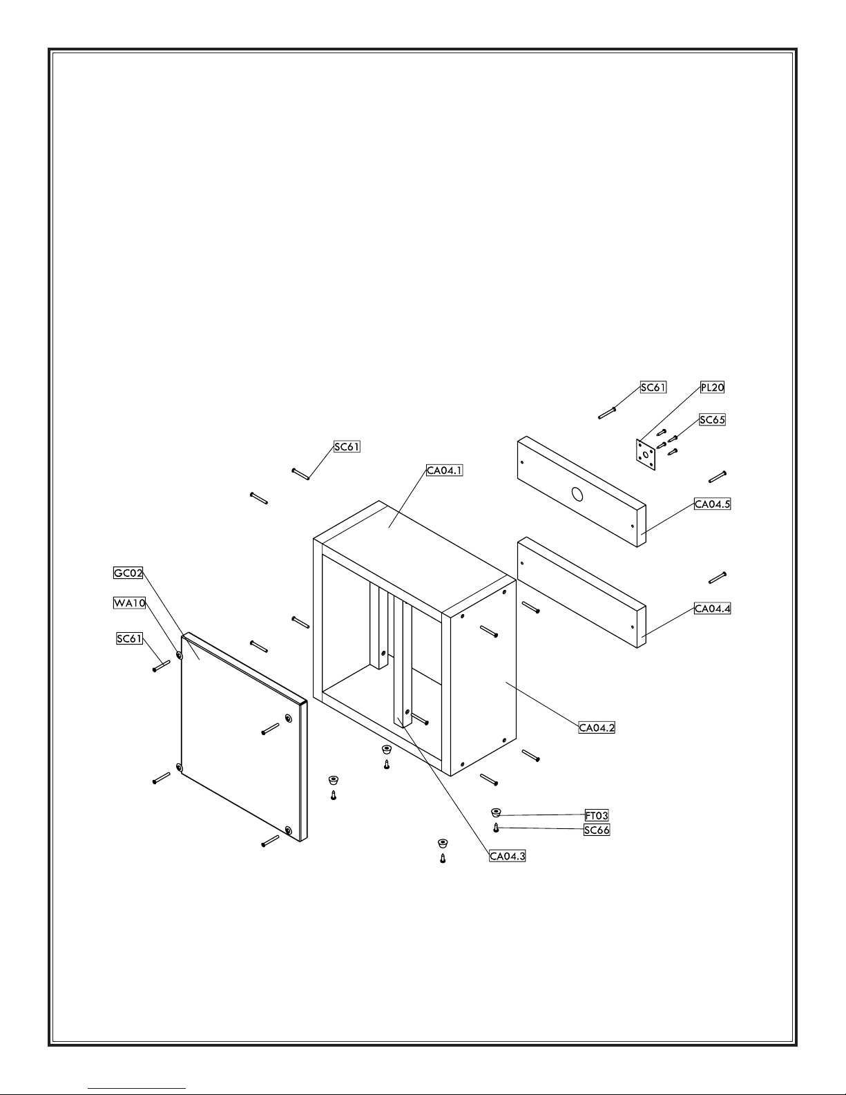
There are three components to your 1x8: the cabinet, the baffle board, and the hookup cable. You can
complete these in any order, but we think the process will be most efficient if you work on them in the
order in which we present them here. In any case, READ THE WHOLE THING THROUGH BEFORE
TIP: Empty
the parts of the kit onto a
cookie sheet or into a big fruit
bowl, NOT onto the cluttered
workbench, or onto the living room
carpet! This will protect you from
losing tiny parts.