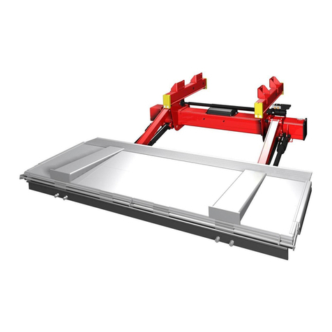
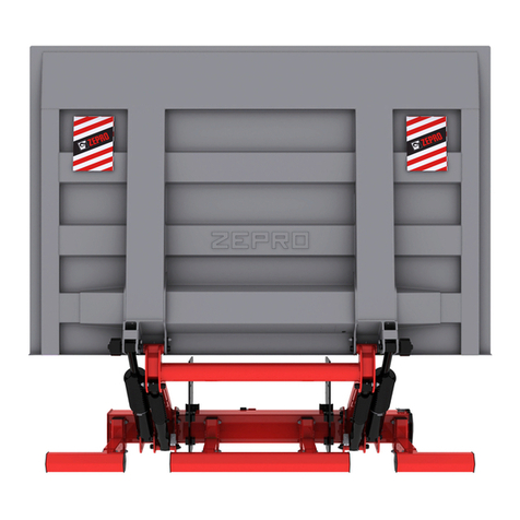
Zepro ZHDN 2500-150 Service manual

ZHDN 2500-150
Sales
Mossvägen 8, 641 49 KATRINEHOLM, SWEDEN
Telephone: 0150 - 489550
Fax: 0150 - 489551
E-mail: [email protected]
Internet: www.z-lyften.se
Factory
Allévägen 4, 840 73 BISPGÅRDEN, SWEDEN
Telephone: 0696 - 17200
Fax: 0696 - 17242
E-mail: [email protected]
Internet: www.z-lyften.se
2016-07-07
75354TL
INSTALLATION INSTRUCTIONS
Z-LYFTEN PRODUKTION AB


ZHDN 2500-150Contents
3
www.zepro.com
Contents
1 Introduction ...................................................................................................... 5
1.1 General .........................................................................................................5
1.2 Important .....................................................................................................5
1.3 CE marking....................................................................................................6
1.4 Hydraulicuid...............................................................................................6
1.5 Idencaon ................................................................................................7
2 Safety rules ........................................................................................................ 8
2.1 Repainng.....................................................................................................8
2.2 Transport plug ..............................................................................................9
2.3 Moving parts - free movement.....................................................................9
2.4 Third-partyequipmentmustnotbeaached............................................10
2.5 Installaon..................................................................................................10
3 Installation workflow ....................................................................................... 11
3.1 Installing the support frame .......................................................................11
3.2 Electricalconnecons.................................................................................11
3.3 Installingtheplaorm ................................................................................11
3.4 Installing cylinders ......................................................................................11
3.5 Aachingdecals..........................................................................................11
4 Calculating the installed dimensions................................................................. 12
4.1 C dimension ...............................................................................................12
4.2 A dimension................................................................................................12
4.3 H dimension................................................................................................12
5 Adjusting the chassis brackets .......................................................................... 14
5.1 Adjustment.................................................................................................14
6 Installation ....................................................................................................... 15
6.1 Chassis brackets.........................................................................................15
6.2 Rear beam cut outs ....................................................................................15
6.3 Support frame ............................................................................................16
6.4 Control power cable ...................................................................................18
6.5 Control devices ...........................................................................................18
6.6 M
ain power cable.......................................................................................19
6.7 O
penplaormalarm ..................................................................................20
6.8 Third-partyequipmentmustnotbeaached............................................20
6.9 Underrunprotecon ..................................................................................21
6.10 Armstops ....................................................................................................23
6.11 Hydraulicautolt........................................................................................23
6.12 Sealing strip (horizontal).............................................................................23
6.13 Sealingstrip(vercal) .................................................................................23
6.14 Plaorm......................................................................................................24
6.15 Purging the cylinders ..................................................................................29
6.16 Transport lock.............................................................................................29

ZHDN 2500-150
4
Contents
www.zepro.com
7 Temporary operation of lift............................................................................... 30
7.1 Connecon .................................................................................................30
7.2 Operaon ...................................................................................................30
7.3 Disconnecon.............................................................................................30
8 Electrical
and
hydraulic drawings ...................................................................... 31
8.1 ZHDN 2500-150 ..........................................................................................31
8.2 ZHD 2500-150, angle sensors .....................................................................32
8.3 Connecngcontroldevice .........................................................................33
8.4 Connecngcontroldevice .........................................................................34
8.5 Connecngcabinswitchandopenplaormalarm....................................35
9 Connection unit ............................................................................................... 36
9.1 Operanginformaon................................................................................36
9.2 Autolt........................................................................................................41
9.3 Funconalschemacdrawing....................................................................42
9.4 Restriconofuseofcontroldevice ............................................................43
9.5 Sensor
....................................................................................................44
9.6 Hydraulic unit .............................................................................................45
10 Marking and decals .......................................................................................... 46
10.1 Summary ....................................................................................................46
10.2 Load diagram..............................................................................................47
10.3 Idencaonplate.....................................................................................47
10.4 Work area ..................................................................................................47
10.5 Driver'sinstrucons....................................................................................48
10.6 Danger area ...............................................................................................48
10.7 Warning tape .............................................................................................48
10.8 CE marking..................................................................................................49
10.9 Warningags.............................................................................................49
11 Lubrication and fluid level check....................................................................... 50
11.1 Lubricaon..................................................................................................50
11.2 Fluid level check .........................................................................................50
12 Testing and verification .................................................................................... 51
12.1 Stacloadtest ............................................................................................51
12.2 Dynamic load test.......................................................................................52
12.3 Testofsafetyfuncons...............................................................................52
13 Disassembly ..................................................................................................... 53
14 Specifications .................................................................................................. 54
14.1 Weights ......................................................................................................54
14.2 Centre of gravity .........................................................................................55
14.3 Maximumpowerconsumpon-Minimumrecommendedconductorcrossseconal
area ............................................................................................................56
14.4 Loading diagram .........................................................................................57
14.5 Tightening torque .......................................................................................58

ZHDN 2500-150
Introducon
5
www.zepro.com
1 Introducon
1.1 General
Z-Lyften is electro-hydraulically driven. An electric motor which gets its power from the truck's
ordinary battery drives a hydraulic pump which supplies uid via hoses to the working hydraulic
cylinders. The hdraulic system is controlled by electric valves which are controlled from push but-
tons on the control devices. The number of available control devices depends on the conguration.
The hydraulic package containing the entire drive system is built into the frame of the lift. The control
system is housed in a separate box. Both systems are easy to access for inspection and service.
The platform is supported by the lift arm which is very strong and rigid. The underrun protection is
bolted directly to the support frame. The platform has a non-slip surface.
The arms are driven by the lift cylinders with integrated hose breakage valves to protect against
possible leakage. The lift cylinders can also be equipped with one or two electric hose breakage
valves. These hose breakage valves can also act as an extra transport lock for the platform.
The tilt function of the platform is also driven by hydraulic cylinders with the same design as the
lift cylinders. The tilt cylinders, too, can be equipped with one or two hose breakage valves. The
speed of lifting and up/down tilting is determined by the oil pump. The lowering speed is controlled
by a so-called constant ow control valve that provides the same speed independent of the load.
The piston rods of the hydraulic valves are treated by a method that provides a very long lifespan.
An integrated bypass valve protects the hydraulic system from overload when lifting and tilting up.
Note that the bypass valve does not prevent overload at rest position or during down movements.
The electricity supply is from the normal vehicle battery. The control power is taken from the central
electrical unit near the driver’s seat. When the control power is off, the lift is locked.
To save battery power, always switch off the control power when the lift is not in use.
The electric motor has a thermostatic switch that isolates the control circuit of the motor contac-
tors if the motor overheats. The control circuit of the motor contactors is connected again once
the motor has cooled down.
The platform can be set to any position from vertical to a 10° decline.
1.2 Important
The following “warning markings” appear in the installation instructions and are intended to draw
your attention to circumstances potentially causing unwanted situations, near misses, personal
injury or damage to the product, etc.
Take care.
Risk of damage to the product.
NOTE.
Take extra care. Risk of personal injury or damage to the product and the surroundings.
mWARNING!
Dust molorio blabo. Et enet eatus, idi dit provit, quam faceseq uuntores as audae etur, quatemp
orerum quiandi con eostius, nis et a praectas ati sequis atectas arcius de volupti amustios vo-
luptatur, qui te vita dem utature rferspiet mo temquam, andis est dolupis minvellaccus am sunt.
Enest, aut odit occaboreium inverovit explaut harchic itametus ut andero qui ofciur renim lacea-
tum que aceatus earumqu idendi blatquid quam verum ditinciet aut parumet modi bearit inctatus,

ZHDN 2500-150
6
Introducon
www.zepro.com
1.3 CE marking
Z-Lyften tail lifts on sale on the European market have been CE marked (CE stands for Conformité
Européenne) since 1/1/1995. The manufacturer guarantees that the product complies with the EU
Machinery Directive.
The aim of the Machinery Directive is to increase the safety of products throughout Europe.
There are some basic general rules that must be followed before Z-Lyften products are installed.
Follow the installation instructions. If it is not possible to follow the installation instructions or if
changes must be made, the changes must be approved by the manufacturer. This is a consequence
of CE marking rules. The manufacturer is unable to certify compliance with the Machinery Direc-
tive if the product is subsequently changed without its knowledge or approval. To retain a valid CE
marking for the product, it is essential to contact Z-Lyften.
Welding is not necessary except where recommended by the manufacturer.
To improve safety we supply decals for the lift that are easy to understand regardless of the lan-
guage. Make sure these decals are attached so that the information they contain can be seen by
the lift operator.
Position control devices so that the operator is in the safest possible location and has a clear view
of the load, the tail lift and the surrounding area. Follow the driver’s instruction manual when using
the control device and its functions.
1.4 Hydraulic uid
A tail lift must work just as well in tropical heat as in the Arctic cold. The heat is no problem for
the uid. Cold, on the other hand, is a big challenge for hydraulic uid. That is why Z-Lyften
chose a hydraulic fuel that can cope with all these conditions. Our hydraulic uid (product no.
21963, 1 litre) is made of highly rened mineral oil. The anti-wear additives are zinc-free and
provide excellent wear protection.
The special temperature properties of the hydraulic uid and the high viscosity index mean that
the hydraulic system can be started in cold weather and runs reliably in uctuating operating
temperatures. Our hydraulic uid also provides excellent corrosion protection for the hydraulic
system.
We also offer a biodegradable hydraulic uid (environmental uid) as an option (product no.
22235, 1 litre) made of a synthetic base oil called polyalphaolen, which is biodegradable. This
base oil has outstanding properties at low and high temperatures. The uid stays liquid down
to temperatures as low as -50 º C. Oxidation stability is very good, resulting in a long service
life with longer replacement intervals. The uid is easy to pump thanks to good ltering and air
separation properties and low density. This minimises the risk of cavitation and foaming. Contact
us for more information.
So-called ATF uid or HF uid cannot be used with Z-Lyften. These uids affect the rubber in
the gaskets and seals and shorten service life.
NOTE.

ZHDN 2500-150
Introducon
7
www.zepro.com
E.g. ZHDN 2500 - 135 MA
1.5 Idencaon
ZHD = Standard model
ZHDN = Narrow frame
Max lifting capacity x 1 (kg)
Max lifting height -135 = 1340 mm
Cylinder model, MA = Double acting Adjustable Tilt
Single acting Single speed Lift
DA = Double acting Adjustable Tilt
Double acting Single speed Lift

ZHDN 2500-150
8
Safety rules
www.zepro.com
2 Safety rules
2.1 Repainng
Piston rods and cylinder covers must
not be painted. Painting could dam-
age the cylinder gaskets.
Boots,
hydraulic hoses and cables
must not be painted/coated as the
solvent in the paint could damage
the hoses/cables and signicantly
impair durability.
NOTE.
Image 1. Piston rods, cylinder covers and
boots must not be painted/coated
Image 2. Hydraulic hoses must
not be painted/coated
Image 3. Cables must not be painted/coated

ZHDN 2500-150
Safety rules
9
www.zepro.com
2.2 Transport plug
When the lift is installed, the trans-
port plug in the hydraulic unit must
be removed and replaced with the
normal tank cap supplied with the
hydraulic unit.
NOTE.
54
8
5
3
2.3 Moving parts - free movement
When the nal inspection* takes place,
the space occupied by the moving
cylinders must be cleared and made
safe. There is a risk of collision be-
tween the cylinder and the following
items: subframe, truck chassis, beam
for rear light (number plate) and the
chassis bracket of the lift (with a short
overhang).
*The nal inspection must be carried
out with the platform at and tilted down
10°. The clearance from the closest part
of the cylinder must be at least 40 mm.
mWARNING!
The platform must not be tilted down
more than 10º from the horizontal.
mWARNING!
min 40mm
10º
10º
Image 4. Replace the transport plug
with the normal tank cap
Image 5. Clearance to the closest part of
the cylinder must be at least 40 mm
Image 6. Platform must not be tilted down
more than 10º from the horizontal

ZHDN 2500-150
10
Safety rules
www.zepro.com
2.4 Third-party equipment must not be aached
You must not attach third-party equipment (electric or hydraulic) to Zepro tail lifts. Attaching
third-party equipment may interfere with the lift system and the safety functions. Risk of injury
and damage. If it is necessary to install other equipment, check the vehicle manufacturer's
body instructions and use the attachment features on the vehicle.
mWARNING!
Image 7. You must not attach third-party equipment to Zepro tail lifts
2.5 Installaon
The platform must not be installed so it cannot reach ground level.
mWARNING!
Zepro tail lifts are only approved for installation with Zepro installation kits.
mWARNING!

ZHDN 2500-150
Installaonworkow
11
www.zepro.com
3 Installaon workow
3.1 Installing the support frame
• Calculating the installed dimensions
• Attaching the mounting jig to the rear beam
• Aligning the support frame
• Mounting the standard chassis brackets
• Detaching the mounting jig
3.2 Electrical connecons
• Installing the control devices
• Installing the control device cables
• Installing the main power cable
3.3 Installing the plaorm
• Installing the platform
• Installing seals and end stops
• Installing the armstops
3.4 Installing cylinders
• Adjusting the tilt cylinder
• Test running
3.5 Aaching decals

ZHDN 2500-150
12
Calculangtheinstalleddimensions
www.zepro.com
A
40
D
C max/min
Position 1, max 950
Position 2, max 990
Max 1500245
4 Calculang the installed dimensions
For easier installation it is useful to calculate and specify the necessary dimensions in advance.
Determine the C dimension rst, then obtain the other dimensions from the relevant table. You
should try to place the lift as high as possible within the specied C dimension in the table. The
chassis brackets can be set to two different heights, which affects the C dimension, see section
"5 Adjusting the chassis brackets" on page 14.
4.1 C dimension
The C dimension is the distance between the top of the support frame and the vehicle oor
level. This dimension governs how far the lift needs to be installed under the vehicle body (D di-
mension) and the space there will be between the lift arms in the upper position and the vehicle
oor level (A dimension).
D dimension
The D dimension is the space the lift needs, measured from the rear edge of the body to the
front edge of the support frame (in the direction of the vehicle). Once the C dimension is deter-
mined, the D dimension can be obtained from the table.
4.2 A dimension
The A dimension is the space provided for the rear beam, i.e. the space there will be between
the lift arms and the vehicle oor with the lift in the raised position. The A dimension depends on
the C dimension.
4.3 H dimension
The H dimension is the height from the ground (unloaded) to the vehicle oor level. The H
dimension must not be greater that the maximum lifting height of the lift. The platform must
always be able to reach ground level.
Image 8. Installed dimensions.
C Position 1 C Position 2 DA
550 * 510 730 211
515 * 475 771 198
475 425 822 182
415 375 866 170
365 325 904 160
315 275 936 151
265 225 964 143
215 175 988 137
* Not possible if the chassis width is below 1300 mm because
the tilt cylinders would conict with the chassis bracket.

ZHDN 2500-150
Calculangtheinstalleddimensions
13
www.zepro.com
1094
719
1174
1200 - 1500
1870
2486
202 or 242
623
100 100
297
62 567-817
133 - 301
Image 9. Installed dimensions
Image 10. Installed dimensions

ZHDN 2500-150
14
Adjusngthechassisbrackets
www.zepro.com
5 Adjusng the chassis brackets
The chassis brackets can be set to two different heights. This affects the distance between the
lift framework and the chassis (202 mm/242 mm). Take this into account when calculating the C
dimension. The brackets must also be tted differently depending on the chassis width, see the
description below.
5.1 Adjustment
1. Undo the 8 bolts and nuts holding the two parts of the bracket together, see illustration
below.
2. Fit the two parts of the bracket in the correct position with the eight bolts and nuts.
If the chassis width is 1300 mm or more, t the lower part to the inside (B) of the upper
part, see illustration below.
If the chassis is narrower than 1300 mm, t the lower part to
the outside (A) of the upper part, see illustration below.
NOTE.
3. Tighten the bolts using a torque wrench. Tightening torque: 180 Nm.
The parts must always be installed with eight screws – two in the front row of holes and
three each in the middle and rear rows of holes.
mWARNING!
202 mm.
242 mm.
Position 1 Position 2
Image 11. Adjusting the chassis brackets
Chassis width
A B B A

ZHDN 2500-150
Installaon
15
www.zepro.com
700
245 245
Amax
6 Installaon
Consult the trailer manufacturer’s body instructions and Zepro’s instruction booklet before
installation.
NOTE.
Zepro tail lifts are only approved for installation with Zepro installation kits.
mWARNING!
6.1 Chassis brackets
1. Place the chassis brackets on the support frame.
2. Adjust the distance between the brackets according to the chassis width and centre the frame so
that the distance from the end of the frame to the bracket is the same on the left and the right.
3. Attach the clamp on the rear of the chassis bracket using the supplied washers and nuts.
4. Tighten the bolts using a torque wrench. Tightening torque: 260 Nm.
Image 12. Fitting the chassis bracket
6.2 Rear beam cut outs
Itisoennecessarytocreatecutoutsintherearbeamtoprovidespacefortheplaormarms
whentheplaormisintheupperposion.Thesizeofthecutoutsdependsonthecalculated
installeddimension“A”,seeillustraonbelow.
1. Measure and mark the location and depth of the cut outs on the rear beam. The two cut outs
must be centred on the rear beam, i.e. both cut outs must be an equal distance from the mid-
point of the beam.
2. Cut along the markings.
3. Grind away any burr or sharp edges.
Image 13. Rear beam cut outs

ZHDN 2500-150
16
Installaon
www.zepro.com
6.3 Support frame
1. Measure and mark the midpoint of
the rear beam of the trailer. See il-
lustration.
2. Bolt or spot-weld the mounting jig
(product no. 51724) to the rear
beam so that both mid-points
match. See illustration.
3. Position the support frame under the
trailer chassis.
4. Temporarily connect the control card
to enable the lift functions, see sec-
tion "7 Temporary operation of lift" on
page 30.
5. Raise the lift arms to the highest
position.
6. Attach the lift arms to the eye of the
jig. Use the normal bolts of the steel
Image 14. Measure and mark the mid-
point of the rear beam of the trailer
Image 15. Bolt or spot-weld the mount-
ing jig to the rear beam

ZHDN 2500-150
Installaon
17
www.zepro.com
platform.
7. The support frame should be positioned as high as possible within the specied C dimension.
Adjust the frame to the ideal height under the trailer chassis. A car jack is useful. If necessary
you can adjust the height of the bracket by installing its upper and lower parts in an alternative
pattern of holes. See section "5 Adjusting the chassis brackets" on page 14.If necessary
adjust the angle of the arms by carefully operating the lift.
8. Fit the support frame to the trailer chassis using the clamps. See illustration
below. Tighten the bolts using a torque wrench. Tightening torque: 180 Nm.
Welding is not permitted on the chassis brackets.
Do not move the lift all the way to the armstops or with the platform tted before all the
bolts are fully tightened against the chassis.
Do not place the lift under load until all bolts are tightened.
NOTE.
9. Remove the mounting jig.
Image 16. Fit the support frame to the trailer chassis using the clamps

ZHDN 2500-150
18
Installaon
www.zepro.com
6.4 Control power cable
See also the trailer manufacturer’s
electrical instructions.
NOTE.
1. Route the control power cable from
the driver’s cabin to the lift.
The cable must be protected with
rubber grommets when it passes
through beams or walls. If there
are quick connectors, make sure
they are effectively protected
from moisture and dirt.
NOTE.
2. Connect the control power cable to
the cabin switch (CS) on the vehicle
instrument panel. Connect to the
on-board electrical system via a 10 A
(12 V), 15 A (12 V) fuse according the
customer's wishes. See the connec-
tion diagram "8.5 Connecting cabin
switch and open platform alarm" on
page 35.
Image 17. Quick connectors must be well protected
Image 18. Control devices
6.5 Control devices
1. Fit the control devices in the desired
locations. They must be positioned
so that the operator is in the safest
possible location and has a clear
view of the load, the tail lift and the
surrounding area.
All cable inlets must be direct
downwards.
NOTE.
2. The control device cable is con-
nected to the control card. If electric
heating for the
coiled cord unit is
required, 5-core cable
may be
ordered. Product no. 21303.
The cord control device must
have a bracket for installation.
Product no. 20302.
NOTE.

ZHDN 2500-150
Installaon
19
www.zepro.com
Image 19. Fuse box must be installed in a well
protected position as close to the battery as possible
There is a risk of pinching and chang, leading in turn to short circuit and cable res, so the earth and supply
cables must be routed outside the clamping yoke (see illustrations). They must also be far enough away
from the edges so they cannot chafe. Make sure that when tted to the chassis and other vehicle parts, the
cables do not chafe against edges, etc. In general, care must be taken when laying all the cables in order
to obtain a longer cable service life and to reduce the risk of unnecessary stoppages.
NOTE.
6.6 M
ain power cable
1. Route the main power cable from
the lift to the battery. Pull the cable
through the plastic casing.
The cable must not be tied to
brake lines or the normal on-
board electrical system. The ca-
ble must be protected with rubber
grommets when it passes through
beams or walls.
NOTE.
2. Fit a 160 A (24 V) or 250 A (12 V)
fuse to the main power cable from
the battery to protect the electrical
system from short circuit and re risk.
The fuse box must be installed in
a well protected position as close
to the battery as possible.
NOTE.
3. Check that the hydraulic unit is ef-
fectively earthed. Certain commercial
vehicle manufacturers provide spe-
cial earth connection points.
4. Test all functions from all control
devices.
Image 20. Earth and supply cables mus be routed outside clamping yoke

ZHDN 2500-150
20
Installaon
www.zepro.com
6.7 O
pen plaorm alarm
ZEPRO recommends installing a strobe lamp on the outside of the trailer body, where the driver
can clearly see it in the rear view mirror. The lamp must be orange in colour. If the platform is not
pressed against the vehicle body, the lamp lights up when the ignition is turned.
The arrangement consists of:
• Pressure sensor on the line to the tilt cylinders
• Cable
• Inline fuse
• Strobe lamp
12/24 V
6.7.1 Installaon
1. Install a strobe lamp on the outside of the trailer body, where the driver can clearly see it in the
rear view mirror.
2. Make connections as shown in the wiring diagram "8.5 Connecting cabin switch and open
platform alarm" on page 35. Install the cable so it is well protected. The cable must be
protected with rubber grommets when it passes through beams or walls. If there are quick
connectors, make sure they are effectively protected from moisture and dirt.
6.7.2 Test running
1. Turn the ignition key when the platform is tilted up and pressed rmly against the vehicle
body. The lamp must be off.
2. Tilt the platform a few degrees from the vertical. The lamp must come on.
3. Leave the platform in the last position and turn off the ignition. The lamp must go off.
4. Turn the ignition back on and the lamp must come on again.
5. Firmly close the platform. The lamp must go off.
6.8 Third-party equipment must not be aached
You must not attach third-party equipment (electric or hydraulic) to Zepro tail lifts. Attaching
third-party equipment may interfere with the lift system and the safety functions. Risk of injury
and damage. If it is necessary to install other equipment, check the vehicle manufacturer's
body instructions and use the attachment features on the vehicle.
mWARNING!
Image 21. You must not attach third-party equipment to Zepro tail lifts
Table of contents
Other Zepro Automobile Accessories manuals
Popular Automobile Accessories manuals by other brands

Silvercrest
Silvercrest KH 2355 operating instructions

CARFACE
CARFACE DO CF105923EF instruction manual

FormFit
FormFit Tough Guard TG 8G17 installation instructions

BM PRO
BM PRO THOR RVMASTER owner's manual

Silvercrest
Silvercrest SFA 40 A2 operating instructions

Nex-tech
Nex-tech GPS Speedometer Head Up Display quick start guide