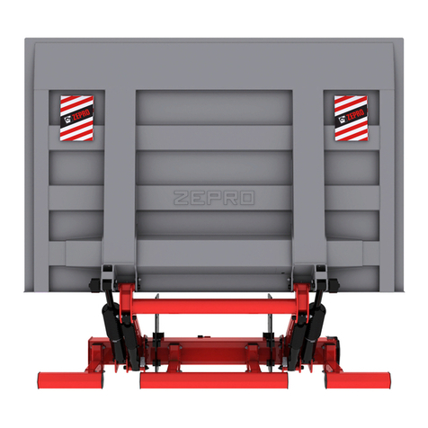
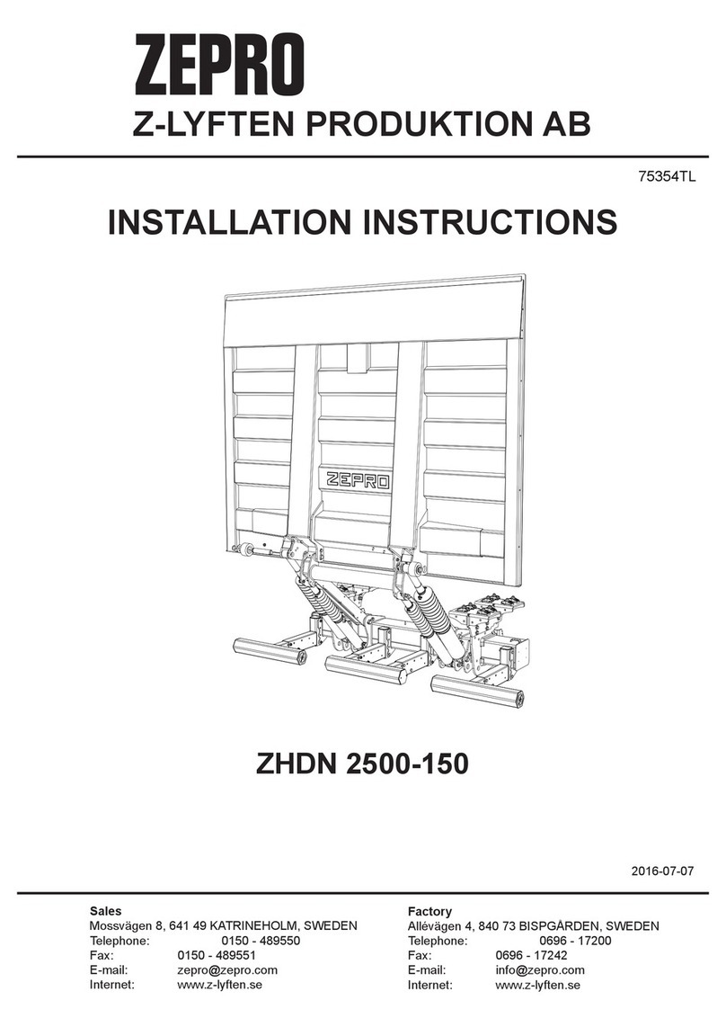
Zepro ZS 150-135 User manual

ZEPRO
Tel.: +46 (0)10-459 05 00
54273TL
2019-11-12
Installation Instruction
Tail Lift
ZS/ZSS 150/200-135/155/175
ZD 150/200-155/175
ZT/ZTS 150/200/250-140
ZS/ZSS 250-135/155


Contents
1. CE marking................................................................................... 4
2. General ......................................................................................... 5
3. Dimensions for installation ........................................................ 9
4. Slider installation......................................................................... 20
5. Electrical installation................................................................... 32
6. Electric and hydraulic diagram .................................................. 35
7. Functional schematic drawing................................................... 42
8. Connection unit ........................................................................... 46
9. Accessories ................................................................................. 52
10. Important information ............................................................... 54
11. Markings, positioning of decals on lift.................................... 55
12. Post installation maintenance.................................................. 57
13. Testing the lift ............................................................................ 58
14. Dismantling................................................................................ 60

4
Since 1/1/1995 ZEPRO tail lifts sold to the European
market are stamped with a CE mark. This is the
manufacturer's guarantee that the product conforms
to the European Machinery Directive.
The application of the European Machinery Directive
is intended to harmonise product safety levels across
Europe.
There are some general principals that should be
made clear when performing the installation of ZE-
PRO lifts.
Follow the installation instructions. If it is not possible
to follow the installation instructions or if modica-
tions are required, the modications must be appro-
ved by the manufacturer. This is a consequence of
the CE marking regulations as it cannot be possible
for a manufacturer to certify conformity to the Machi-
nery Directive if the product is subsequently changed
without his knowledge or approval. In order for the
product's CE marking to remain applicable the forms
supplied by ZEPRO must be completed in case of
modication.
Welding is not necessary unless specically recom-
mended by the manufacturer.
In order to increase security, additional decals, which
are diagrammatic and easily understood indepen-
dent of language will be sent with the lifts.
Ensure that these decals are axed so that the infor-
mation contained on them is available for all users of
the lift.
Position the control unit to ensure that the operator
has a good view of the load, the working area and
the loading area, whilst maintaining a safe
distance from the risk zone between the platform and
the body. Follow the operator’s instructions for use of
the control unit and its functions.
1. CE marking

5
The ZEPRO-lift is electro-hydraulically driven. An
electric motor which gets its power from the truck's
ordinary battery drives a hydraulic pump which supp-
lies oil via hoses and pipes to the working hydraulic
cylinders. The system is steered by electrical valves.
The hydraulic power unit with all details is built into
the lift's support frame. The control system is built
into a seperate box. Both systems are easy to reach
for service and maintenance.
The platform is supported by the lift arm which is
very strong and rigid. The platform has a non-slip
surface.
The lift arm lifting work is done by lift cylinders
which have built in mech. safety valves for protec-
tion against hose breakage. The lift cylinder circuit
is equipped with 1 or 2 electric safety valves, which
are leakproof. These safety valves can also act as a
transport lock for the platform.
The platform's tilt function is also provided by tiltcy-
linders which have built in mech. safety valves for
protection against hose breakage. The tilt cylinder
circuit is equipped with 1 or 2 electric safety valves,
which are leakproof. These safety valves can also
act as a transport lock for the platform. Lifting and
tilting up speed are xed by the pump capacity.
Lowering and tilting down speeds are controlled by
special constant ow valves. These valves give the
same speed independent of the load.
The cylinder piston rods are treated with carbon
nitriding which gives them very long life.
The hydraulic system is protected with a pressure
regulator when lifting or tilting up.
Note! This regulator does not prevent overload at
rest position or lowering.
The electric power is taken from the truck's ordinary
starter motor. Control current is taken from the dash
board. When the control current's isolator (cabin)
switch is o, the lift is "locked". Fixed control units
are electrically heated to prevent condensation da-
mage to switches.
To save current the control current should be swit-
ched o when the lift is not used.
The lift can also be operated from other, optional
units.
To ensure safe operation even with very long control
cables, the hydraulic unit is equipped with relays.
The relays situated in the electrical connection box
placed in the support frame steer current directly
from the main cable to the valves and the main
switch for the motor.
The electric motor is equipped with a thermostat
which breaks the current if the motor becomes over-
heated. The motor will stop until it is cool again.
The platform can be tilted to all positions from verti-
cal to 10° below the horizontal. It has a mechanical
or electric lock which must be activate during trans-
port.
Hydraulic oil
A tail lift should operate just as well in tropical as
in arctic climates. Heat does not adversely eect
the hydraulic oil, however, low temperatures are
more critical. ZEPRO therefore supply a hydraulic
oil that meets the demands across the temperature
range. ZEPRO oil (art.no 21963 for 1 litre) is made
of a highly rened mineral oil, the lubricant additive
is free from zinc and gives good protection against
component wear. The hydraulic oil’s low temperature
properties and high viscosity index allow hydraulic
system start in a very cold climate and give reliable
functioning with varying temperature conditions. With
ZEPRO oil the hydraulic system also receives a very
good protection against corrosion.
ZEPRO also has a biologically degradable oil (art.
no 22235 for 1 litre)available which is based on a
synthetic base oil. This also provides very good pro-
perties at low and high temperatures. It is even liquid
down to -50° C. Resistance to oxidation is extremely
good which gives long lifetime with longer intervals
between oil changes. Good ltration and air sepera-
tion together with low density make the oil easy to
pump. This minimises risk for cavitation and deve-
lopment of scum. Contact us for more information.
2. General
Technical description
NB. Neither ATF nor HF oil should be used in the ZE-
PRO hydraulic circuit as they can damage the rubber
in the sealing kits and reduce their lifetime.

6
Some components of the tail lift must be manipulated by ceiling cranes and therefore could represent ha-
zards if their weights exceed the crane's permitted load. The following are the ranges of weights for various
heavy components.
2. General
Weights
ZS = Single folded platform, for truck installation,
hydraulic motor placed above support frame.
ZSS = Single folded platform, for truck installation,
hydraulic motor placerad in front of support frame.
ZD = Double folded platform, for truck installation,
hydraulic motor placed above support frame.
ZT = Single folded platform, for trailer installation,
hydraulic motor placed above support frame.
ZTS = Single folded platform, for trailer installation,
hydraulic motor placerad in front of support frame.
Max liftcapacity x 10 (kg)
Max lifting height --135 = 1350 mm, -140 = 1450 mm
-155 = 1540 mm, -175 = 1725 mm
Cylindermodel, ML = Double acting Tilt, limited stroke
Single acting one speed Lift
DL = Double acting Tilt, limited stroke
Double acting one speed Lift
E.g. ZS - 150 - 135 ML
_ _ - _ _ _ - _ _ _ _ _
Identication list, slider lifts
Lift components (part of cpl. lift chassis).
Support frameZS/ZSS/ZD 150/200/250 84 kg
Support frame ZT-ZTS 150/200/250 76 kg
Lift arm ZS/ZSS/ZD 150/200-135 46 kg
Lift arm ZS/ZSS/ZD 250-135 50 kg
Lift arm ZS/ZSS/ZD 150/200-155 50 kg
Lift arm ZS/ZSS/ZD 250-155 54 kg
Lift arm ZS/ZSS/ZD 150/200-175 54 kg
Lift arm ZT-ZTS 150/200/250-140 51 kg
Lift cylinder ZT/ZTS 150-140 13,1 kg/pce.
Lift cylinder ZT/ZTS 200/250-140 14,3 kg/pce.
Lift cylinder ZS/ZSS/ZD 150/200-135 8,5 kg/pce.
Lift cylinder ZS/ZSS/ZD 150/200-155 9,5 kg/pce.
Lift cylinder ZS/ZSS/ZD 150/200-175 10,5 kg/pce.
Tilt cylinder ZT/ZTS 150/200/250-140 14,5 kg/pce.
Tilt cylinder ZS/ZSS/ZD 150/200-135 13 kg/pce.
Tilt cylinder ZS/ZSS/ZD 150/200-155 14,5 kg/pce.
Tilt cylinder ZS/ZSS/ZD 150/200-175 16 kg/pce.
Lift cylinder ZS/ZSS/ZD 250-135 11 kg/pce.
Lift cylinder ZS/ZSS/ZD 250-155 12,3 kg/pce.
Tilt cylinder ZS/ZSS/ZD 250-135 13,5 kg/pce.
Tilt cylinder ZS/ZSS/ZD 250-155 15 kg/pce.
Rollarm cpl. (only ZD) 12 kg
Hydraulic auto-tilt 10 kg
Cpl. Lift chassis (without platform)
(1590 mm slide proles)
ZS/ZSS-150/200-135 => 401 kg
ZS/ZSS-250-135 => 412 kg
ZS/ZSS-150/200-155 => 410 kg
ZS/ZSS-250-155 => 421 kg
ZS/ZSS-150/200-175 => 419 kg
1370 mm slide proles instead of 1590 mm -10 kg
1550 mm slide proles instead of 1590 mm -2 kg
(1095 mm slide proles)
ZD-200-155 => 393 kg
ZD-200-175 => 402 kg
1215 mm slide proles instead of 1095 mm +4 kg
(1700 mm slide proles)
ZT/ZTS 150-140 => 415 kg
ZT/ZTS 200/250-140 => 418 kg

7
ZS/ZSS/ZD 150, ZT/ZTS 250 (160 bar)
12 volt 24 volt
245 A
4,2 A
1,5 A
1,5 A
1,5 mm2
35 mm2
50 mm2
-
170 Ah
9 Volt
125 A
2,1 A
0,75 A
0,85 A
1,5 mm2
35 mm2
35 mm2
50 mm2
180 Ah
18 Volt
7000
ZS/ZSS/ZD 200/250 (200 bar)
12 volt 24 volt
250 A
4,2 A
1,5 A
1,5 A
1,5 mm2
35 mm2
50 mm2
-
170 Ah
9 Volt
150 A
2,1 A
0,75 A
0,85 A
1,5 mm2
35 mm2
35 mm2
50 mm2
180 Ah
18 Volt
7000
ZT/ZTS 150/200 (130 bar)
12 volt 24 volt
245 A
4,2 A
1,5 A
1,5 A
1,5 mm2
35 mm2
50 mm2
-
170 Ah
9 Volt
125 A
2,1 A
0,75 A
0,85 A
1,5 mm2
35 mm2
35 mm2
50 mm2
180 Ah
18 Volt
7000
2. General
Max Power Consumption
Pump - Motor Unit
Magnet (hydraulic unit)
Magnet (electric safety valve)
Solenoid
Cable area:
Control cable
Main cable <8 m
Main cable 8-15 m
Main cable >15 m
Power source:
Min. capacity
Min. voltage
Pump - Motor Unit
Magnet (hydraulic unit)
Magnet (electric safety valve)
Solenoid
Cable area:
Control cable
Main cable <8 m
Main cable 8-15 m
Main cable >15 m
Power source:
Min. capacity
Min. voltage
Pump - Motor Unit
Magnet (hydraulic unit)
Magnet (electric safety valve)
Solenoid
Cable area:
Control cable
Main cable <8 m
Main cable 8-15 m
Main cable >15 m
Power source:
Min. capacity
Min. voltage

8
ZT/ZTS-150/200/250 ZS/ZSS/ZD-150/200/250
Loading Diagram
2. General

9
3. Dimensions for installation
Underrun Protection
Try to install the slider prole in a position so that, when it is folded, the rear edge of the platform is in line with
the rear edge of the vehicle body so that the platform can be folded out. Ensure that the installation position is
such that the lift when folded meets the legal dimensions for underrun protection. See illustration below,
• Distance between the beam and the ground when the vehicle is unloaded: Max. 550 mm.
• Horizontal distance from the outermost part of the platform to the underrun protection: Max. 375 mm.
Max 550 mm
Max 375 mm

10
ZS-150/200/250-135
1226
245 245
A max
210
max 1360
220
P2 P1
62
180
Cmax 525
max 445
A
max 835
130
1972
max 900 min 750
15
110
1314
176
150222
277
380
81
80
*max 630
980
3. Dimensions for installation
Sliderprole length
Total Overhang O
- 600 1370
1590
1700
600 - 800
800 -
P1 (mm) Slide prole
length (mm)
*NOTE: If the cables are a limiting factor, be
careful to check the overhang
*at max frame width 1040
C
525
500
450
400
350
300
235
A
198
183
169
158
145
130
100
P1
545
675
750
P2
1005
960
910
O
1605
1735
1810
1500 / 2000 kg
C
630
600
550
450
450
400
350
A
200
187
172
161
153
134
114
P1
545
675
750
P2
1005
960
910
O
1667
1797
1872
2500 kg
(P1 in Steel)

11
1972
max 900 min 750
15
110
1314
176
1226
245 245
A max
210
max 1540
220
P2 P1
62
180
Cmax 635
max 520
A
max 905
130
ZS-150/200/250-155
150222
277
380
81
80
*max 630
980
3. Dimensions for installation
Sliderprole length
Total Overhang O
- 700 1590
1700700 -
P1 (mm) Sliderprole
length (mm)
NOTE: If the cables are a limiting factor, be
careful to check the overhang
*at max frame width 1040
C
635
600
550
500
450
400
350
A
210
191
177
167
158
147
134
P1
545
675
750
P2
1005
960
910
O
1725
1855
1930
1500 / 2000 kg
C
740
700
650
600
550
500
450
A
209
201
179
168
160
148
136
262 118 400 121
370 106
P1
545
675
750
P2
1005
960
910
O
1787
1917
1992
2500 kg
(P1 in Steel)

12
1972
max 900 min 750
15
110
1314
176
1226
245 245
A max
210
max 1720
220
P2 P1
62
180
Cmax715
max 620
A
max1005
130
ZS-150/200-175
150222
277
380
81
80
*max 630
980
3. Dimensions for installation
Sliderprole length
Total Overhang O
- 700 1590
1700700 -
P1 (mm) Sliderprole
length (mm)
NOTE: If the cables are a limiting factor, be
careful to check the overhang
*at max frame width 1040
C
715
700
650
600
550
500
450
A
205
195
182
172
164
157
145
P1
545
675
750
P2
1005
960
910
O
1845
1975
2050
1500 / 2000 kg
C
740
700
650
600
550
500
450
A
209
201
179
168
160
148
136
400 135 400 121
370 106
P1
545
675
750
P2
1005
960
910
O
1787
1917
1992
2500 kg
(P1 in Steel)
370 106
350 121
305 110

13
1972
max 900 min 750
15
22
1314
176
1226
245 245
A max
C
630
600
550
500
450
400
350
A
200
187
172
161
153
134
114
210
max 1360
220
P2 P1 130
180
Cmax 630
max 450
A
max 730
150 222 150222
277
280
ZSS-150/200/250-135
100
P1
545
675
750
P2
1005
960
910
O
1667
1797
1872
- 550 1370
1590
1700
550 - 700
700 -
P1 (mm)
130
160
*max 840
*max 565
980
3. Dimensions for installation
Sliderprole length
Total Overhang O
Slide prole
length (mm)
(2500 kg: P1 in Steel)
NOTE: If the cables or valve system are
a limiting factor, be careful to check the
overhang.
*at max frame width1040

14
1972
max 900 min 750
15
22
1314
176
1226
245 245
A max
C
740
650
600
550
450
400
209
201
179
168
160
148
136
121
210
max 1540
220
P2 P1 130
180
Cmax 740
max 520
A
max 800
ZSS-150/200/250-155
- 600 1590
1700
1820
600 - 800
800 -
P1 (mm)
P1
545
675
750
P2
1005
960
910
O
1787
1917
1992
106
700
A
370
500
150 222 150222
277
280
100
130
160
*max 840
*max 565
980
3. Dimensions for installation
Sliderprole length
Total Overhang O
Slide prole
length (mm)
(2500 kg: P1 in Steel)
NOTE: If the cables or valve system are
a limiting factor, be careful to check the
overhang.
*at max frame width1040

15
C
820
800
750
700
650
600
550
500
A
206
199
185
174
166
159
148
138
1972
max 900 min 750
15
22
1314
176
1226
245 245
A max
210
max 1720
220
P2 P1 130
180
Cmax 820
max 620
A
max 900
ZSS-150/200-175
P1
545
675
750
P2
1005
960
910
O
1907
2037
2112
- 550 1590
1700
1820
550 - 700
700 -
P1 (mm)
1500 / 2000 kg
125
450
150222
277
280
100
130
160
222
150
*max 840
*max 565
980
3. Dimensions for installation
Slide prole length
Total Overhang O
Sliderprole
length (mm)
*NOTE: If the cables are a limiting factor, be careful to check the
overhang
*at max frame width1040
NOTE: If the cables or valve system are
a limiting factor, be careful to check the
overhang.

16
ZD-150/200-155
150 150
222
277
380
1226
245 245
A max
1972
max 900 min 750
15
110
1314176.5
220
P2 P1
max 1540
A
210
62
max 520
180
130
max 905
C max 635
C
635
600
550
500
A
210
191
177
167
450 158
400 147
350 134
285 118
P1
754
P2
639
O
1250
1500 / 2000 kg
80
*max 630
980
3. Dimensions for installation
Slide prole length 1095
Total overhang O
NOTE: If the cables are a limiting factor, be
careful to check the overhang
*at max frame width 1040

17
ZD-150/200-175
1226
245 245
A max
1972
max 900 min 750
15
110
1314176.5
220
P2 P1
max 1720
A
210
62
max 620
180
130
max 1005
C
715
700
650
600
550
500
A
205
195
182
172
164
157
450 145
400 135
350 121
305 110
C max 715
P1
879
P2
764
O
1350
1500 / 2000 kg
150
222
277
380
80
*max 630
980
3. Dimensions for installation
Slide prole length 1215
Total overhang O
*NOTE: If the cables are a limiting factor, be
careful to check the overhang
*at max frame width 1040

18
660
240 240
A max
C
450
400
350
300
250
200
A
217
206
186
170
150
125
ZT-150/200/250-140
80
*max 750
920
Slide prole length 1590
Total overhang O
3. Dimensions for installation
*NOTE: If the cables are a limiting factor, be
careful to check the overhang
*at max frame width 1300
1740
min 1200 - max 1300
159
728
166
1740
min 1200 - max 1300159
728
166
210
max 1470
240
P2 P1
62
180
Cmax 450
max 480
A
max 1020
537
271
110 431 210
(2500 kg: P1 in Steel)
P1 P0
945 2044
875 1974
750 1849
675 1774
O
1060
1005
960
910
880

19
457
660
240 240
A max
C
540
500
450
400
350
300
270
A
225
207
191
179
170
163
159
ZTS-150/200/250-140
130
160
*max 980
*max 705
920
3. Dimensions for installation
Slide prole length 1590
Total Overhang O
*at max frame width 1300
NOTE: If the cables or valve system are
a limiting factor, be careful to check the
overhang.
1740
min 1200 - max 1300159
728
166
P1
786
786
715
P2
960
910
910
O
1916
1916
1845
(2500 kg: P1 in Steel)
210
max 1450
238
P2 P1 130
180
Cmax 540
max 472
A
max 915
443
185
110 431 210
1096

20
ZS
ZD
ZSS
ZTS
ZT
O
O
O
O
O
4. Slider installation
Attention! Also refer to the truck manufacturer´s instructions for auxiliary equipment
IMPORTANT: Finding the installation position of the
slider is very simple if these instructions are follo-
wed.
The platform and lift arm combinations described on
this page are optimised for minimum total over-
hang (O), therefore always install the slide prole
rear edge level with the rear edge of the vehicle
frame or tow hook device so that the platform
can fold out.
If the slide frame is placed further forward there is a
risk (particularly for low ground clearance) that the
platform will not be able to fold out. There are only
two solutions. Either to move the slide frame to the
position that we recommend or choose a dierent
platform combination, but the new platform would
have shorter rst and second folding part (and hence
perhaps be too short for your needs).
With these short overhang models the working posi-
tion is not the same as the folding out position.
Make the cut-outs as required in the rear beam in
accordance with the measures on previous pages.
This manual suits for next models
25
Table of contents
Other Zepro Automobile Accessories manuals
Popular Automobile Accessories manuals by other brands

POOL-LINE
POOL-LINE 110085 Assembly instructions

VBG
VBG Onspot Mounting instruction/Spare Parts List

Malone
Malone SaddleUp PRO Series Installation & Loading Instructions

Tyger
Tyger TG-BP6J85368 installation instructions

Lippert
Lippert Curt 16613 instruction manual

Atera
Atera STRADA SPORT M quick start guide