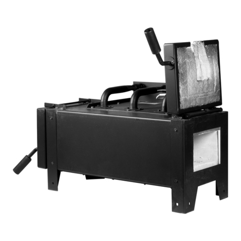
Ziegler & Brown GRAND TURBO ZGGTSBBIL User manual

ZGGTSBBIL
GRAND TURBO BARBEQUE DROP-IN BUILD-IN SIDE BURNER
appliance
1
Natural Gas

Both ends open
FIGURE3 - OUTDOOR AREA-EXAMPLE 3 FIGURE4 - OUTDOOR AREA-EXAMPLE 4
FIGURE5 - OUTDOOR AREA-EXAMPLE 5
30 percent or more total
of the remaining wall area
is open and unrestricted
30 percent or more total
of the remaining wall area
is open and unrestricted
Open side at
least 25% of
total wall area
Open side at
least 25% of
total wall area
2
FIGURE1 FIGURE2 no more than two walls.

EXPLODED VIEW
carton
3
Most parts already pre-assembled in the factory.
*

4
OUTER
(
(
CADOU24621435NG NG INJECTOR(INNER)

appliance appliance
appliance
in the
vicinity of this appliance.
appliance
appliance
fireboxes periodically.
Keep
5
Always w
appliance

appliance
appliance
appliance
appliance
appliance
appliance
appliance
appliance
appliance
appliance
an adjacent cupboard
the
Connect the regulator end of the hose and regulator assembly to the cylinder as shown below.
6
starting

appliance
appliance
appliance
The 1.75 mm factory fitted NG injector is already in place behind the LP injector and is the correct size for NG use.
appliance
appliance
appliance
Make sure that the correct hose assembly is properly connected to the appliance and to the bayonet.
7
starting
Lighting Instructions:
1. Read all instructions before lighting
2. Do not proceed until the leak test as outlined earlier has been conducted.
3. Make sure the control knob is in the OFF position. Open the side burner lid.
4. Make sure the gas supply is ON.
5. Push the control knob IN and keep pressing in whilst turning the control knob anti-clockwise to HIGH
(a click will be felt). This should light the burner.
6. If the burner does not light, turn the control knob clockwise to OFF, wait 5 minutes and repeat step 5.
If the burner does not light, or does not stay alight, repeat steps 5 and 6.
7. If the burner fails to light or to stay alight after several attempts, contact your supplying Barbeques
Galore store for advice using the contact details at the rear of this manual.
8. Adjust the heat by turning the control knob between the HIGH and LOW positions.
9. To SHUT DOWN, turn the gas supply OFF and then turn the control knob clockwise to the OFF position.
Q
sed person
fol

Product Code: ZGGTSBBIL
Product type: ZIEGLER & BROWN GT BUILD-IN
DROP-IN SIDE BURNER L-SERIES
Gas type:
Gas pressure:
Injector:
Gas consumption:
PROPANE NG
2.75kPa 1.0 kPa
1.12mm 1.75mm
15MJ/h 14MJ/h
IAPMO Oceana Certification No: GMK10138
Minimum clearance from combustible materials:
1000mm overhead, 300mm sides and rear
8

PRODUCT DIMENSIONS
Check the product dimensions and cut-out requirements BEFORE commencing
any preparations to fit the appliance.
9

CUT-OUT REQUIREMENTS
The control box can be placed in various positions as above.
All dimensions are in mm.
The hole in the bench top for the side burner needs to be 394 2mm X 484 2mm.
The hole for the control box needs to be 204 2mm X 154 2mm
Minimum 210mm clearance below the bench top is required. It is
recommended to use a non-combustible barrier at least 210mm below the
bench top between any gas cylinder below.
maxmax
max
max
max
min
min
Installation must be in
accordance with Australian
Standard AS5601 and any
local regulations.
Bench top must be a non-combustible material.
Minimum clearance
from combustible materials:
1000mm overhead,
300mm sides and rear.
+
-
+
-
+
-
+
-
10
Gas cylinder compartments must have permanent openings ventilating
directly to the outside of the appliance, and consisting of either—
(a) perforations, uniformly distributed over the height of the enclosure and
with a total free area of not less than 25% of the sidewall area; or
(b) separate openings at high and low level, such that—
(i) the total free area at high level is not less than 20 000 mm2 and is within
125 mm of the top of the cylinder compartment; and
(ii) the total free area at low level is not less than 20 000 mm2, and—
(A) at least 25% of the required area is within 15 mm of the base of the
cylinder compartment;
(B) the total required area is within 125 mm of the base of the cylinder
compartment; and
(C) the openings cannot be obstructed by the cylinder(s).

Fit the control box into the hole as shown below. Be careful not to jam or kink
the corrugated gas pipe or hose and regulator as the control box is positioned.
Before lighting check for leaks carefully as outlined on page 6. In some assembly
situations, it may be necessary to disconnect the corrugated pipe from the control
box, fit it first to the firebox, fit the firebox into position, bring the pipe out through
the control box hole, fit the pipe to the control box, then fit the control box into
position.
ALWAYS TEST FOR LEAKS BEFORE LIGHTING
A)Connect the corrugated gas pipe to
the firebox as shown. Start by hand,
turn clockwise, and then tighten firmly
with a spanner as shown. The injector
must be engaged firmly and centrally
into the firebox.
B)Fix the ignition wire to the spark pin
on the control valve as shown below.
Place the firebox into the hole as shown. Be careful not to jam or kink the
ignition wire as the firebox is positioned.
Step 2
Step 4
Step3
11

MAKE SURE ALL CONTROL KNOBS & CYLINDER VALVES ARE IN OFF POSITION.
appliance
This appliance is certified for use with either Liquid Propane (LP Gas) or Natural Gas.
The necessary injector to convert the appliance for use with natural Gas is already factory fitted behind the
LP injector. For bayonet connection to a Natural Gas supply, connection hose kit NGCK250VJQ is available
separately through Barbeques Galore stores.
and gas supply is disconnected from the appliance prior to performing the conversion.
valve
12

Step 1:Disconnect ignition wire from
the control box as above shown
Step 2:Disconnect the corrugated
pipe from the burner as above shown
Step 3:Disconnect the LP
injector, leaving the 1.75mm
NG exposed and in place as
shown above.
Step 4:Reconnect the ignition
wire to the control box.
Step 5: Reconnect the corrugated pipe that
now holds the new 1.75 mm injector back in
place into the side burner.
13
TECHNICAL INFORMATION: Natural Gas Conversion (continued)

14
Step 6.The minimum setting for the gas valve needs to be changed to ensure the flame does
not blow out when there is a breeze. The setting will initially be tuned for LP use.
Take care to use its initial setting as a reference point. Adjust the minimum setting as follows:
a)Remove the control knob from the valve by pulling the knob forward.
b)Identify the small hole near and under the centre of the main shaft as shown below.
c)Used a 6mm flat head screwdriver and turn the adjusting screw 180 degrees anticlockwise (half of
one full turn). DO NOT turn 360 degrees!
Step 7. Change the gas type label to “NATURAL GAS”.
Replace the existing “PROPANE ONLY” gas type label inside the lid with the “NATURAL GAS”
label included with the conversion kit.
Step 8. Disconnect the LP gas hose and regulator from the appliance. Make sure all users are
aware of the new gas type. Connection of the appliance to Natural Gas supply and commissioning
of the appliance for Natural Gas must only be performed by a licensed gas fitter.
Keep the old LP injector somewhere safe in case conversion back to LP is ever required.

Appliance
Appliance
the burner
burner
appliance
1. Remove trivet and carefully remove burner.
2. Check the burner for any blockages etc. Some spider webs can be almost impossible to see, but can stop the
burner functioning. Use a pipe cleaner to ensure the burner and burner ports are web free and unblocked.
15

Burners easily extinguished in low wind.
firebox
16
appliance

appliance
appliance
appliance
appliance
appliance
appliance
appliance
Frequent rinsing with fresh water will make a huge difference to corrosion prevention.
appliance
17
C
appliance

Firebox inner, firebox outer, lid and control box.
18
C

19
Table of contents
Popular Burner manuals by other brands

Town & Country Fireplaces
Town & Country Fireplaces TC42.NG03C instruction manual

Avanzini
Avanzini DRAGO P1 Assembly instructions

baltur
baltur BT 250 DSG-4T Instruction

Beckett
Beckett AF manual

Sandberg
Sandberg 133-77 user guide

KitchenAid
KitchenAid KBZU122VSS Installation Instructions and Use & Care Guide

baltur
baltur TBG 55PN-V instructions

Charmglow
Charmglow Drop-In Side Burner owner's manual

Forgemaster
Forgemaster COMPANION manual

Bentone
Bentone BENTOFLEX ST 146 B30A Installation and maintenance instruction

Bentone
Bentone BF 1 FU Installation and maintenance instruction

Riello
Riello RDB 3.2 50/70 Mistral Installation, use and maintenance instructions