Ziegler DigiTrace RAYSTAT-ECO-10 User manual

RAYSTAT-ECO-10
Energy-saving freeze protection
controller
Energiesparendes Steuergerät
für Frostschutzanwendungen
Régulateur économique pour
la mise hors gel
üwww.ze-gmbh.de
ZIEGLER ENGINEERING

2
ENGLISH
Table of contents ...................................................................................... 2
Description & Technical data ............................................................................................. 6
Functional description ............................................................................... 7
Display ...................................................................................................... 7
Installation description .............................................................................. 8
Operational description ............................................................................. 11
Testing, commissioning and maintenance ................................................. 14
Wiring diagrams ........................................................................................ 33
Commissioning sheet ................................................................................ 36
DEUTSCH
Inhaltsverzeichnis ................................................................................................................. 2
Beschreibung und technische Daten ............................................................................. 15
Funktionsbeschreibung ........................................................................................................ 16
Display ......................................................................................................................................... 17
Montage ...................................................................................................................................... 18
Programmierung ..................................................................................................................... 20
Test, Inbetriebnahme und Wartung ................................................................................ 23
Anschlussdiagramme ................................................................................ 33
Inbetriebnahmeprotokoll ........................................................................... 36
FRANÇAIS
Table des matières ............................................................................................................. 2
Description & caractéristiques techniques ................................................................. 24
Fonctionnement ...................................................................................................................... 25
Afficheur ...................................................................................................................................... 26
Installation ................................................................................................................................ 27
Paramétrage .............................................................................................................................. 29
Test, mise en service et entretien ................................................................................... 32
Schémas électriques ................................................................................. 33
Fiche de mise en service ........................................................................... 36
RAYSTAT-ECO-10

3
V
DE
A
8
3
246
5
9a
19b

4
B
1. 2. 3.
4. 5. 6.

DEUTSCH
A 1. Gehäuse
2, 3, 4, 5. Einführungen
(2 x M25, 1 x M20, 1 x M16)
6. Temperatursensor Pt 100
7. Sensorkabel
8. Steuerungstasten
9. Digitales Display
FRANÇAIS
A 1. Boîtier du régulateur
2, 3, 4, 5. Entrées de câbles
(2 x M25, 1 x M20, 1 x M16)
6. Sonde de température Pt 100
7. Câble de la sonde
8. Touches de programmation
9. Afficheur numérique
ENGLISH
A 1. Controller enclosure
2, 3, 4, 5 Cable entries
(2 x M25, 1 x M20, 1 x M16)
6. Temperature sensor Pt 100
7. Sensor cable
8. Push buttons
9. Digital display
B 1. Tournevis 3 mm
2. Tournevis 5 mm
3. Cutter
4, 5, 6. Clés (19 mm, 24 mm,
27 mm)
B 1. Schraubendreher 3 mm,
Längsschlitz
2. Schraubendreher 5 mm,
Kreuzschlitz
3. Kabelmesser
4, 5, 6. Schraubenschlüssel
(19 mm, 24 mm, 27 mm)
B 1. Terminal screwdriver 3 mm
2. Posi-drive screwdriver 5 mm
3. Trimming knife
4, 5, 6. Spanners (19 mm,
24 mm, 27 mm)
5

6
Description
RAYSTAT-ECO-10 is an electronic controller with display, advanced alarm
facilities and the capability of switching large currents.
The RAYSTAT-ECO-10 is designed to control heating cable systems. Heat-
ing cable can be controlled either directly by the RAYSTAT-ECO-10 or via a
contactor.
Direct switching of heating cables is possible for heating loads up to 25 A.
For heating loads greater than 25 A indirect switching via a suitably rated
contactor controlled by a RAYSTAT-ECO-10 is necessary.
Installation and all wiring must be in accordance with applicable regulations.
The device must be installed in non hazardous areas only.
Tyco Thermal Controls offers other controls for use in hazardous areas.
Technical data
Supply voltage: 230 Vac. +10%/–10%, 50/60 Hz (6V leakproof
maintenance-free non-rechargeable battery
incl. for programming without power supply)
Main relay: max. 25 A, 250 Vac. Resistive
Heater operation on
sensor error: programmable: ON or OFF
Set point T range: 0°C to + 30°C
Accuracy: ±0,5 K at 5°C
Operatingtemperature: –30°C (–20°C, VDE approved) to +40°C ambient
User interface: 4 x 7 segment digital display
4 push buttons
alarm relay, max. 2 A, 250 Vac. (Potential free)
Power terminals: 3 x 0,75 mm2to 4 mm2
Alarm terminals: (3 + ) x 0,75 mm2to 2,5 mm2
Sensor terminals: (3 + ) x 0,75 mm2to 2,5 mm2
Heater terminals: (2 + ) x 0,75 mm2to 4 mm2
Enclosure
Exposure Temperature: –40°C to +80°C
Ingress Protection: IP 65
Entries: 2 x M25, 1 x M20, 1 x M16
Size: 120 x 160 x 90 mm
Weight: approx. 800 gr.
Material: polycarbonate
Lid fixing: 4 captive screws
Mounting: on a wall or directly on the pipe using support
brackets, SB-100 / SB-101

7
T sensor
Type: 3-wire Pt 100 according to IEC Class B
Sensor head: 50 mm x ∅6 mm
* An external Pt 100 sensor can be connected, the sensor cable can be
extended with a 3-core shielded cable of 20 Ωmax. per conductor (e.g. up
to 150 m with a 3 x 1.5 mm2cable)
Functional description
The Raystat-ECO-10 Controller is used to control heat-tracing freeze pro-
tection systems based on ambient temperature. The controller adjusts the
power of the heating cable by energizing the circuit for a percentage of a
complete cycle. This percentage is determined based on the ambient tem-
perature, the set point, and the minimum expected ambient temperature. The
full cycle time is influenced by pipe diameter.
For example, if the ambient temperature is halfway between the minimum
expected ambient temperature and the set point, the heating cable will be
energized for 5 minutes and be off for 5 minutes (for the smallest pipe size
selected). The actual duty-cycle periods and ratios vary, depending on the
ambient temperature and the above mentioned parameters. This algorithm is
called Proportional Ambient Sensing Control (PASC).
If you are unsure about the min. expected ambient setting, set it to a higher
rather than a lower value to prevent freeze-ups.
In the event of an error, the alarm relay switches and an error code shows on
the display. It is possible to program the status of the heating cable (ON or
OFF) in case of a sensor error.
The unit is fitted with a battery so that programming can be done on the
bench prior to mounting in the working location (see Operational description,
page 11).
Display
RAYSTAT-ECO-10 has a digital display. The three left hand digits 9a are the
value display and the right hand digit 9b is the status display.

8
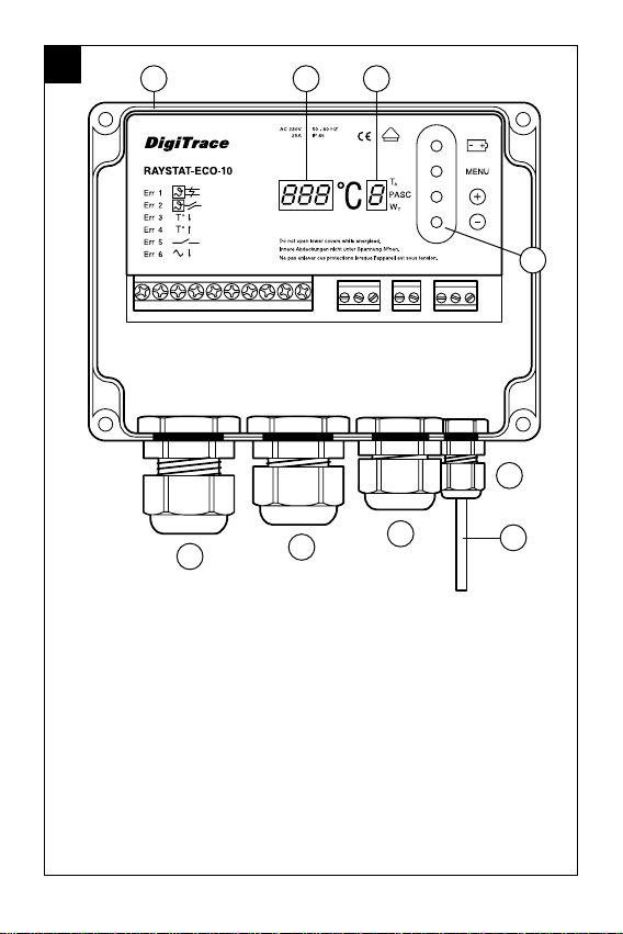
There are 4 different display modes possible:
1. In the normal operation mode (no error condition), the measured temper-
ature or the set point temperature value are displayed in the value display
(alternating).
During the time that the actual measured temperatures is shown, the TA
LED in the status display lights up.
At the moment that the set point temperature is shown, the WTLED in the
status display lights up.
Also during normal operation, the middle horizontal LED in the status
display lights up when the PASC algorithm is active.
For example: means –5°C measured temperature and PASC is
active; means set point temperature 5°C and PASC is active.
2. In case an error is detected, the value display shows “ ” (flashing)
and the status display indicates the error number (see Errors).
3. Programming is done by means of the push buttons (see Operational
description). In the programming mode, the status display will indicate
the code of the parameter that is selected. The value display indicates the
value for the parameter.
4. When power is initially applied, all display segments will illuminate for a
short period. This will also occur if no mains power is available and the
battery button is pressed. Do not push the battery button when the unit is
powered, as this will shorten battery life.
Installation description
1. Installation of heating cable
For design and selection of heating cables in sanitary applications, follow the
Technical Handbook.
For selection of industrial heating cables, follow the Selection Guide for
Industrial Trace-Heating Systems or use the latest version of TraceCalc or
contact Tyco Thermal Controls.
Follow the design guidelines and install the system in accordance with the
system specifications.
Follow the “Product Safety Notice” supplied with the heating cable.
Residual current device (RCD 30 mA) is required.
The RAYSTAT-ECO-10 is a sensitive electronic device, and should be installed
taking care of common guidelines for EMC interference.

9
2. Mounting of the enclosure
The RAYSTAT-ECO-10 can be installed indoor or outdoor.
Do not install the thermostat under the thermal insulation.
A. Wall mounting
Mount the enclosure using wall fasteners (screws) via the four, 4 mm ∅
holes.
B. Mounting on a pipe
Tyco Thermal Controls offers different support brackets (not included) to
mount the RAYSTAT-ECO-10 on a pipe: SB-100 or SB-101.
3. Wiring
Remove the terminal protection cover to access the terminals.
Power cable
Enter a single phase (230 Vac.) power cable through the M25 gland 2 (see
drawing A ) and wire according to the wiring diagram (page 33).
Wiring the heating cable can be done either:
A. Via junction box or contactor or when using RayClic with the cold cable
through the M25 gland 3 .
B. Directly into RAYSTAT-ECO-10.
In this case, the M25 gland 3 , which is delivered pre-mounted to the
RAYSTAT-ECO-10, is to be replaced by an appropriate kit.
Follow instructions supplied with the kit for installation.
Important: For Voltage Free Operation, the wire links (W1) and (W2) need to
be removed. Failure to remove the wire links can result in damage to the unit
or to other connected equipment. Wiring of RAYSTAT-ECO-10 to a remote
alarm is optional through the M20 gland 4 . Tyco Thermal Controls strongly
recommends the use of a remote alarm for critical operations (e.g. when
extreme low temperatures (lower than –25°C) can be expected or for critical
processes).

10
4. Installation of the sensor
Location of the sensor
Mount the sensor in a position exposed to normal weather conditions but
shielded from direct sunlight. The sensor should not be located against
surfaces that are heated from within or may be heated by sunlight. If the
RAYSTAT-ECO-10 is located outdoors, the sensor cable may be shatened and
the sensor may be mounted directly to the bottom of the housing, but make
sure that at least 35 - 40 mm of the sensor extends beyond the gland fitting
and that the sensor is not in contact with other cables.
Warning: Do not install sensor at ambient temperatures below –20°C. Do not
bend sensor, keep it straight under all circumstances.
Wiring sensor to RAYSTAT-ECO-10
Enter the sensor cable through the indicated M16 gland 5 and wire as
shown in the wiring diagram (page 33). Please pay attention to color coding
of the wiring.
Remark: The sensor cable can be extended up to 150 m when a cross sec-
tion of 3 x 1.5 mm2is used (max. 20 Ωper conductor).
The connection between sensor cable and sensor extension can be made in
junction box JB-86 or equivalent. Use a shielded cable for extension to avoid
interference. The shielding braid is to be earthed in the thermostat.
5. Complete installation
Put the terminal protection cover back in place.
If RAYSTAT-ECO-10 is not yet programmed, please do so as described in
Operational description (page 11) and onwards.
Close the lid of the unit.

11
Operational description
1. Introduction
The RAYSTAT-ECO-10 parameters are configured via a menu system.
The unit is delivered with a battery so that the operating parameters can be
set up without any need for the power supply to be connected. This is useful
for setting units on the bench prior to mounting in their working location or
on site when power isn’t available.
Please note that the Battery key ( ) must not be pressed whilst the unit
has the power supply connected. It will cause the battery to discharge im-
mediately. The battery will be disconnected automatically when the last para-
meter has been set.
Once programmed, the settings will be retained even in case of power loss.
2. Activating and navigating the Menu in Set-Up mode
In order to activate the Set-up mode when the unit is not connected to a
mains power supply, press the Battery key ( ) for about 2 sec.
This action will immediately light up all segments of the display, so correct
functioning of the display can be verified. The display will then shortly show
, and switch to the first parameter to be changed.
In order to activate the Set-up mode when the unit is connected to a mains
power supply (the display alternates between the setpoint and actual meas-
ured temperature), press the MENU key for about 2 sec. The display will
shortly show , and switch to the first parameter to be changed.
Stepping through the complete parameter list can be done by successively
pressing the MENU key. When the last parameter has been set, the display
will show , and return to normal operation. In case the unit is not con-
nected to a power supply, the battery will be disconnected.
If the unit is in Set-up mode, but no keys are activated, it will return to the
normal operation (or switch the battery off when the battery is used) after
about 30 sec.
To alter any parameter shown in the display, press the + or – keys. This will
allow the parameter to be raised or lowered to the maximum or the minimum
in integer steps.
If you require to reset all parameters to their default value, press the + and
– keys together for about 2 sec. If this is succesful, the display will show
.

12
3. Parameters
The first parameter to show up during Set-up mode is the Set Point. Other
parameters, their default, minimum and maximum values are shown in the
below table:
Parameter Default Displayed Min. Max.
Value Code
Set Point (°C) 5 0 30
Min. Expected Ambient1(°C) –20 –30 0
Pipe Size2 1 1 3
Heater Operation if 1 0 (OFF) 1 (ON)
Sensor Error
Voltage Free Operation 0 0 (NO) 1 (YES)
1Min. Expected Ambient Temp. is the temperature whereby the heating
cable is energized for 100%.
Min. Expected Ambient Temp. can only be set in steps of 10 K.
Min. Expected Ambient = Low Temp. Alarm.
2Select Pipe Size Diameter:
3 for pipes ≥2 inch.
2 for pipes ≥1 inch.
1 for pipes <1 inch.

13
4. Errors
RAYSTAT-ECO-10 can differentiate between 5 errors. The error is displayed
as soon as the error condition is detected. The alarm relay switches at the
same moment. The value display indicates “ ” (flashing) and the status
display indicates the error number.
Error Code Description Remedy
Short Circuit Sensor Replace sensor
(or very low resistance)
Open Circuit Sensor Connect sensor cable or
replace sensor
Temperature below Verify appropriateness
Min. Expected Ambient of setting
Output Voltage Error1Relay or triac malfunction /
replace unit
Supply below 207 Vac.2Verify supply voltage
1Detection of this error is disabled in Voltage Free Mode.
2Unit is not active when supply voltage is below approx. 190 Vac.
All alarms are on the same alarm relay.
An alarm will clear automatically as soon as the error condition is gone.
There is no need to reset; all settings are maintained.
If multiple alarms are active, the alarms are shown with the following prior-
ity: (Highest), , , , (Lowest)
Note: is not applicable to RAYSTAT-ECO-10.

14
Testing, commissioning and maintenance
Test heating cable when thermostat installation is complete as directed in the
instructions applicable for the heating cable. Fill out the commisioning sheet
(page 3514).
Maintain thermostat during normal plant maintenance.
Check: Mounting is firm
Exposed sensor cable is not damaged
Glands are tightened firmly
Thermostat operation is correct (no error code displayed)
Thermostat settings suits application
Lid is closed firmly.
Cladding is sealed with sealant.
Disposal of Waste batteries
(Applicable regulations for the European Union)
The crossed out dustbin on the product and/or packaging indicates that the
battery contained in the product shall not be disposable as part of normal
household waste.
The batteries must be disposed of responsibly to avoid potentially negative
consequences to the environment and/or human health.
The recycling of the materials can also help conserve natural resources.
For more information on battery disposal, please contact your local civic of-
fice or your domestic waste disposal service.

15
Beschreibung
Das elektronische Steuergerät RAYSTAT-ECO-10 ist mit einem digitalen Dis-
play und umfassenden Alarmfunktionen ausgestattet. Es wurde speziell für
die Begleitheizsysteme entwickelt und ist für hohe Belastungen ausgelegt.
Das Heizband kann entweder direkt über das Steuergerät oder einen Leis-
tungsschütz geschaltet werden. Bei einem Schaltstrom von max. 25 A ist
eine Schaltung über den Thermostaten zu empfehlen. Sollen mehr als 25 A
geschaltet werden, 50 ist ein Leistungsschütz zu verwenden.
Die Installation und der Anschluss des Steuergerätes müssen entsprechend
den örtlich geltenden Bestimmungen erfolgen.
Das Steuergerät RAYSTAT-ECO-10 darf nicht in explosionsgefährdeten Berei-
chen installiert werden. Für explosionsgefährdete Bereiche bietet Tyco Thermal
Controls spezielle Steuergeräte an.
Technische Daten
Betriebsspannung: AC 230V, +10%/–10%, 50/60 Hz
(inkl. einem auslaufgeschützten, wartungs-
freien, nicht-wiederaufladbaren 6 V-Akku)
Nennstrom: max. 25 A bei AC 230 V, ohmsche Last
Begleitheizung bei Programmierbar: EIN oder AUS
Sensorfehler:
Temperaturbereich: 0°C bis +30°C
Schaltpunktgenauigkeit: ±0,5 K bei 5°C
Umgebungstemperatur –30°C (–20°C, VDE zertifiziert) bis +40°C
bereich:
Benutzerschnittstelle: Digitales Display
4 Tasten zur Programmierung
Alarmrelais, Wechsler potentialfrei, max. 2 A,
AC 230 V
Stromanschluss: 3 Anschlussklemmen für 0,75 bis 4 mm2
Alarmrelais-Anschluss: 3 Anschlussklemmen (+ ) für 0,75 mm2
bis 2,5 mm2
Sensorkabel-Anschluss: 3 Anschlussklemmen (+ ) für 0,75 mm2
bis 2,5 mm2
Steuerrelais-Anschluss: 2 Anschlussklemmen (+ ) für 0,75 mm2
bis 4 mm2

16
Gehäuse
Umgebungstemperatur-
bereich: –40°C bis +80°C
Schutzart: IP65
Bohrungen: 2 x M25, 1 x M20, 1 x M16
Abmessungen: 120 x 160 x 90 mm
Gewicht: ca. 800 g
Material: Graues Polycarbonat
Deckelbefestigung: 4 x M6, Zylinderkpfschrauben - rostfreier
Stahl, unverlierbar
Montage: Wandmontage oder auf Befestigungswinkel
SB-100/SB-101
Temperatursensor
Typ: in 3-leitertechnik Pt 100 (IEC Class B)
Sensor: 50 mm x ∅6 mm
*
Es kann ein externer Pt 100-Sensor angeschlossen werden. Das Sensorkabel
kann mit einem 3-adrigen abgeschirmten Kabel, max. 20 W je Leiter, verlän-
gert werden (bis zu 150 m bei einem Leiterquerschnitt von 3 x 1,5 mm2)
Funktionsbeschreibung
Das Steuergerät RAYSTAT-ECO-10 wird zur Steuerung, unter Erfassung der
Umgebungstemperatur, von selbstregelnden Frostschutzsystemen eingesetzt.
Das Steuergerät passt die Ausgangsleistung des Heizbandes durch eine pro-
zentuale Energieversorgung des Heizkreises in Bezug auf eine Zykluszeit an.
Der Prozentsatz wird durch die gemessene Umgebungstemperatur, die Halte-
temperatur und die minimal zu erwartende Umgebungstemperatur bestimmt.
Die volle Zykluszeit wird festgelegt durch den Rohrdurchmesser.
Beispiel: Liegt die gemessene Umgebungstemperatur genau zwischen der
minimal zu erwartenden Umgebungstemperatur und der eingestellten Hal-
tetemperatur, so wird das Heizband für 5 min eingeschaltet und für 5 min
abgeschaltet ( bei 1 Zoll Rohrnennweite). Periodendauer und -verhältnis
hängen von den zuvor erwähnten Parametern ab. Diese Art der Steuerung
wird umgebungstemperatur-proportionale Steuerung bezeichnet.
Wenn Sie nicht sicher sind, welchen Wert Sie bei der minimalen Umgebungs-
temperatur eingeben sollen, so wählen Sie einen etwas höheren Wert um
Frostschäden zu vermeiden.

17
Bei einer Störung schaltet das Alarmrelais, und in der Anzeige erscheint eine
Fehlermeldung. Sie können außerdem eingeben, ob das Begleitheizsystem
bei einem Sensorausfall abschalten oder weiter in Betrieb bleiben soll (EIN
oder AUS).
Das Steuergerät ist zusätzlich mit einer Batterie (im Lieferumfang) ausgestat-
tet, so dass die Programmierung auch ohne Netzspannungsanschluss vorge-
nommen werden kann (siehe „Programmierung“ auf Seite 20).
Display
Das Steuergerät RAYSTAT-ECO-10 ist mit einem digitalen Display ausge-
stattet. Das dreistellige Display links 9a gibt die Messwerte an, die Anzeige
rechts 9b den Status.
Die Anzeige rechts gibt an, in welchen Betriebszustand sich die Begleithei-
zung befindet:
1. Bei normalem Betrieb werden die aktuelle Umgebungstemperatur oder der
Sollwert für die Haltetemperatur links im Display abwechselnd angezeigt..
Solange die aktuelle Umgebungstemperatur angezeigt wird, leuchtet die
LED TAin der Statusanzeige rechts. Wenn die Haltetemperatur im linken
Display angezeigt wird, leuchtet die LED WTin der Statusanzeige. Im Nor-
malbetrieb leuchtet auch die LED in der Mitte. Sie zeigt an, dass der PASC-
Algorithmus aktiviert ist.
Beispiel: bedeutet, es werden aktuell –5°C gemessen, und der
PASC-Algorithmus ist aktiv. bedeutet, die Haltetemperatur beträgt
5°C, und der PASC-Algorithmus ist aktiviert.
2. Im Falle einer Störung blinkt in der linken Anzeige die Meldung „ “,
und in der Statusanzeige erscheint ein Fehlercode (siehe „Fehlermeldun-
gen“).
3. Die Programmierung erfolgt mit Hilfe der Bedientasten (siehe „Funktions-
beschreibung“). Während der Programmierung erscheint in der Status-
anzeige der Code für den Parameter, der gerade programmiert wird. Im
linken Display wird gleichzeitig der jeweilige Wert angezeigt.
4. Wird die Spannungsversorgung eingeschaltet, so leuchten alle Segmente
im Display kurzzeitig auf. Dies geschieht auch, wenn keine Spannungsver-
sorgung angeschlossen ist und die Batterie-Taste gedrückt wird. Drücken
Sie die Batterie-Taste niemals, wenn eine Spannungsversorgung ange-
schlossen ist, da sich sonst die Lebensdauer der Batterie verkürzt.

18
Montage
1. Heizbandmontage
Informationen zur Auswahl und Auslegung von Frostschutzsystemen in der
Bautechnik finden Sie in unserem Technischen Handbuch.
Eine detaillierte Auswahlhilfe für industrielle Begleitheizsysteme von Tyco
Thermal Controls finden Sie in unserer Projektierungsanleitung für industrielle
Begleitheizsysteme, bzw. in unserer speziell entwickelten Planungssoftware
„TraceCalc“. Für Fragen zu Ihrer individuellen Anwendung wenden Sie sich
bitte direkt an Ihre Tyco Thermal Controls-Vertretung.
Um die ordnungsgemäße Funktion des Systems sicherzustellen, müssen die
Auslegungsvorschriften und die Montageanleitung exakt befolgt werden. Be-
achten Sie bitte auch das mitgelieferte Sicherheitsdatenblatt.
Hinweis: Es ist ein Fehlerstromschutzschalter (30mA) erforderlich.
Der RAYSTAT-ECO-10 ist ein empfindliches elektronisches Gerät und sollte
unter Berücksichtigung der allgemeinen Richtlinien zur elektromagnetischen
Verträglichkeit (EMV) installiert werden.
2. Gehäusemontage
Das Steuergerät RAYSTAT-ECO-10 kann im Freien oder innerhalb von Gebäu-
den montiert werden. Montieren Sie das Gerät nicht unter der Wärmedäm-
mung!
A. Wandmontage
Für die Wandmontage sind vier Löcher für M4-Schrauben im Gehäuse.
B. Montage auf der Rohrleitung
Tyco Thermal Controls bietet auch Befestigungswinkel (nicht im Lieferum-
fang enthalten) für die Montage des Steuergerätes auf der Rohrleitung an:
SB-100 oder SB-101.
3. Anschluss
Entfernen Sie zuerst die Gehäuseabdeckung.
Anschlusskabel
Führen Sie ein 3-adriges Anschlußkabel (AC 230V) durch die dafür vorgese-
hene M25-Verschraubung 2 (siehe Zeichnung A ) und schließen Sie das
Kabel entsprechend dem Anschlußdiagramm auf Seite 33 an.

19
Heizbandanschluss
A. Das Heizband kann über einen Anschlußkasten, ein Leistungsschütz oder
RayClic mit dem Kaltende des Anschlußmoduls direkt durch die M25-Ver-
schraubung 3 angeschlossen werden.
B. Das Heizband kann auch direkt im Steuergerät angeschlossen werden. In
diesem Fall muss die M25-Verschraubung 3 , die bei der Lieferung bereits
am Steuergerät montiert ist, durch eine entsprechende Anschlussgarnitur
ersetzt werden (siehe Tabelle S. 20). Montieren Sie die Anschlussgarnitur
entsprechend der mitgelieferten Montageanleitung.
Hinweis: Für potentialfreien Betrieb müssen die Verbindungskabel (W1
und W2) entfernt werden, da sonst das Steuergerät oder andere, daran
angeschlossene Komponenten beschädigt werden können. Über die M20-
Verschraubung (4) kann das Steuergerät RAYSTAT-ECO-10 auch an eine ex-
terne Alarmeinheit angeschlossen werden. Für Anwendungen mit speziellen
Anforderungen empfiehlt Tyco Thermal Controls den Einsatz einer externen
Alarmeinheit (z.B. bei extrem niedrigen Umgebungstemperaturen (unter
–25°C) oder kritischen Prozessen).
4. Sensormontage
Montageort des Sensors
Montieren Sie den Sensor an einer Stelle, wo er normalen Wetterbedingun-
gen, jedoch nicht direkter Sonneneinstrahlung ausgesetzt ist. Der Sensor
sollte ebenfalls nicht auf Oberflächen montiert werden, die indirekt von der
Sonne erwärmt werden. Wenn das Steuergerät RAYSTAT-ECO-10 im Freien
montiert wird, kann das Sensorkabel gekürzt und der Sensor direkt am Ge-
häuseboden montiert werden. In diesem Fall sollten Sie jedoch sicherstellen,
dass der Sensor mindestens 35–40 mm über die Verschraubung hinausragt
und nicht in Kontakt mit anderen Kabel kommt.
Warnung: Montieren Sie den Sensor nicht bei Umgebungstemperaturen un-
ter –20°C. Verbiegen Sie den Sensor auf keinen Fall.
Anschluss des Sensors an das Steuergerät
Führen Sie das Sensorkabel durch die dafür vorgesehene M16-Verschrau-
bung 5 und schließen Sie es entsprechend dem Anschlussdiagramm auf
Seite 37 an. Bitte beachten Sie die Farbcodierung der einzelnen Adern!
Hinweis: Das Sensorkabel kann mit einem 3-adrigen abgeschirmten Kabel,
max. 20 Ωje Leiter, verlängert werden (bis zu 150 m bei einem Leiterquer-
schnitt von 3 x 1,5 mm2). Die Verbindung zwischen Sensorkabel und Verlän-
gerungskabel kann in einem Anschlusskasten vom Typ JB-86 (oder gleich-
wertig) erfolgen. Verwenden Sie ein geschirmtes Kabel, um Interferenzen zu
vermeiden. Das Schutzgeflecht muss im Thermostat geerdet werden.

20
Funktionsbeschreibung
1. Einleitung
Die RAYSTAT-ECO-10 Parameter sind über ein System-Menü einstellbar.
Das Steuergerät ist zusätzlich mit einer Batterie ausgestattet, so dass die
Programmierung auch ohne Netzspannungsanschluss erfolgen kann.
Bitte beachten Sie, dass die Batterie-Taste ( ) nur gedrückt werden
darf, wenn das Steuergerät nicht unter Spannung steht, da sich die Batterie
ansonsten sofort entlädt. Der Batteriebetrieb wird nach Eingabe des letzten
Parameters automatisch beendet.
Die Programmierung bleibt auch nach einem Spannungsausfall erhalten.
2. Programmierung
Um den Programmiermodus ohne Spannungsversorgung zu aktivieren,
drücken sie die Batterie-Taste für ca. 2 Sekunden. Alle Segmente im Display
leuchten sofort kurzzeitig auf. Auf diese Weise können Sie feststellen, ob
das Display fehlerfrei funktioniert. Im Display erscheint kurz und
anschließend der erste einstellbare Parameter.
Um den Programmiermodus bei Netzbetrieb zu aktivieren (im Display er-
scheint abwechselnd Haltetemperatur oder aktuelle gemessene Temperatur),
drücken Sie die Menü-Taste für ca. 2 Sekunden. Im Display erscheint kurz
und anschließend der erste einstellbare Parameter.
Die einstellbaren Parameter können schrittweise durch drücken der Menü-
Taste aufgerufen werden. Nach Eingabe des letzten Parameters erscheint
im Display und das Gerät arbeitet wieder im Normalbetrieb.
Im Fall, daß das Steuergerät nicht an die Netzspannung angeschlossen ist,
wird der Batteriebetrieb beendet.
Befindet sich das Gerät im Programmiermodus und es werden keine Tasten
betätigt, so schaltet das Steuergerät nach 30 Sekunden in den Normalbetrieb
zurück (bei Batteriebetrieb wird diese abgeschaltet).
Die im Display erscheinenden Parameter lassen sich schrittweise mit den
Taste + und – verändern.
5. Fertigstellung der Montage
Bringen Sie die Gehäuseabdeckung wieder an. Wenn Sie das Steuergerät
RAYSTAT-ECO-10 noch nicht programmiert haben, folgen Sie nun den Hin-
weisen im Kapitel „Programmierung“ auf Seite 20. Schließen Sie den Deckel
des Gehäuses.
Table of contents
Languages:
Popular Thermostat manuals by other brands

Omega Engineering
Omega Engineering HCTB-3040 Operator's manual

Salus
Salus CT100 instruction manual

Honeywell
Honeywell EConnect TL9160AR operating manual

American Standard
American Standard SELECTRONIC 605XTMV installation instructions

White Rodgers
White Rodgers 1F83-277 user manual

Aprilaire
Aprilaire 8620 installation instructions