ZIEHL-ABEGG Fcontrol FTET4AHMQ-L User manual

Fcontrol
FTET4/6/10AHMQ-L
Ventilation computer with frequency inverter for 1 ~ fans in
agriculture
Operating Instructions
Keep for reference!
Software version: D2512A from Version 02.00
L-BAL-E139-GB 2022/03 Index 006 Part.-No.
english

Content
1 General notes . . . . . . . . . . . . . . . . . . . . . . . . . . . . . . . . . . . . . . . . . . . . . . . . . . . . . . . . . . . . . 5
1.1 Meaning of the operating instructions . . . . . . . . . . . . . . . . . . . . . . . . . . . . . . . . . . . . . . 5
1.2 Target group . . . . . . . . . . . . . . . . . . . . . . . . . . . . . . . . . . . . . . . . . . . . . . . . . . . . . . . . . 5
1.3 Exclusion of liability . . . . . . . . . . . . . . . . . . . . . . . . . . . . . . . . . . . . . . . . . . . . . . . . . . . 5
1.4 Copyright . . . . . . . . . . . . . . . . . . . . . . . . . . . . . . . . . . . . . . . . . . . . . . . . . . . . . . . . . . . 5
2 Safety instructions . . . . . . . . . . . . . . . . . . . . . . . . . . . . . . . . . . . . . . . . . . . . . . . . . . . . . . . . . 5
2.1 Intended use . . . . . . . . . . . . . . . . . . . . . . . . . . . . . . . . . . . . . . . . . . . . . . . . . . . . . . . . 5
2.2 Explanations of symbols . . . . . . . . . . . . . . . . . . . . . . . . . . . . . . . . . . . . . . . . . . . . . . . . 6
2.3 Product safety . . . . . . . . . . . . . . . . . . . . . . . . . . . . . . . . . . . . . . . . . . . . . . . . . . . . . . . 6
2.4 Requirements placed on the personnel / due diligence . . . . . . . . . . . . . . . . . . . . . . . . 6
2.5 Start-up and during operation . . . . . . . . . . . . . . . . . . . . . . . . . . . . . . . . . . . . . . . . . . . . 6
2.6 Work on the device . . . . . . . . . . . . . . . . . . . . . . . . . . . . . . . . . . . . . . . . . . . . . . . . . . . 7
2.7 Modifications / interventions in the device . . . . . . . . . . . . . . . . . . . . . . . . . . . . . . . . . . 7
2.8 Operator’s obligation of diligence . . . . . . . . . . . . . . . . . . . . . . . . . . . . . . . . . . . . . . . . . 7
2.9 Employment of external personnel . . . . . . . . . . . . . . . . . . . . . . . . . . . . . . . . . . . . . . . . 8
3 Product overview . . . . . . . . . . . . . . . . . . . . . . . . . . . . . . . . . . . . . . . . . . . . . . . . . . . . . . . . . . 8
3.1 Operational area . . . . . . . . . . . . . . . . . . . . . . . . . . . . . . . . . . . . . . . . . . . . . . . . . . . . . . 8
3.2 Service work . . . . . . . . . . . . . . . . . . . . . . . . . . . . . . . . . . . . . . . . . . . . . . . . . . . . . . . . . 8
3.3 Transport . . . . . . . . . . . . . . . . . . . . . . . . . . . . . . . . . . . . . . . . . . . . . . . . . . . . . . . . . . . 8
3.4 Storage . . . . . . . . . . . . . . . . . . . . . . . . . . . . . . . . . . . . . . . . . . . . . . . . . . . . . . . . . . . . . 8
3.5 Disposal / recycling . . . . . . . . . . . . . . . . . . . . . . . . . . . . . . . . . . . . . . . . . . . . . . . . . . . 8
4 Mounting . . . . . . . . . . . . . . . . . . . . . . . . . . . . . . . . . . . . . . . . . . . . . . . . . . . . . . . . . . . . . . . . . 9
4.1 General notes . . . . . . . . . . . . . . . . . . . . . . . . . . . . . . . . . . . . . . . . . . . . . . . . . . . . . . . . 9
4.2 Minimum space requirement . . . . . . . . . . . . . . . . . . . . . . . . . . . . . . . . . . . . . . . . . . . . 9
4.3 Outdoor installation . . . . . . . . . . . . . . . . . . . . . . . . . . . . . . . . . . . . . . . . . . . . . . . . . . . . 9
4.4 Installation location for agriculture . . . . . . . . . . . . . . . . . . . . . . . . . . . . . . . . . . . . . . . . 9
4.5 Temperature influences during commissioning . . . . . . . . . . . . . . . . . . . . . . . . . . . . . . . 10
5 Electrical installation . . . . . . . . . . . . . . . . . . . . . . . . . . . . . . . . . . . . . . . . . . . . . . . . . . . . . . . 10
5.1 Safety precautions . . . . . . . . . . . . . . . . . . . . . . . . . . . . . . . . . . . . . . . . . . . . . . . . . . . . 10
5.2 EMC-compatible installation . . . . . . . . . . . . . . . . . . . . . . . . . . . . . . . . . . . . . . . . . . . . . 10
5.2.1 Motor cable . . . . . . . . . . . . . . . . . . . . . . . . . . . . . . . . . . . . . . . . . . . . . . . . . . . 10
5.2.2 Control cables . . . . . . . . . . . . . . . . . . . . . . . . . . . . . . . . . . . . . . . . . . . . . . . . . 10
5.3 Mains connection . . . . . . . . . . . . . . . . . . . . . . . . . . . . . . . . . . . . . . . . . . . . . . . . . . . . . 11
5.3.1 Mains voltage . . . . . . . . . . . . . . . . . . . . . . . . . . . . . . . . . . . . . . . . . . . . . . . . . 11
5.3.2 Required quality attributes for the mains voltage . . . . . . . . . . . . . . . . . . . . . . . . . . 11
5.3.3 Leakage current, securely attached, protective earth conductor . . . . . . . . . . . . . . 11
5.4 Systems with residual current protective devices . . . . . . . . . . . . . . . . . . . . . . . . . . . . . 11
5.5 Inverter output . . . . . . . . . . . . . . . . . . . . . . . . . . . . . . . . . . . . . . . . . . . . . . . . . . . . . . . 11
5.5.1 Motor connection . . . . . . . . . . . . . . . . . . . . . . . . . . . . . . . . . . . . . . . . . . . . . . . 11
5.5.2 Disconnection between controller and motor (repair switch) . . . . . . . . . . . . . . . . . 12
5.6 Motor protection function for motors with thermostats . . . . . . . . . . . . . . . . . . . . . . . . . 12
5.7 Analog inputs for sensors . . . . . . . . . . . . . . . . . . . . . . . . . . . . . . . . . . . . . . . . . . . . . . . 12
5.8 Control output 0 - 10 V (A1, A2, A3) . . . . . . . . . . . . . . . . . . . . . . . . . . . . . . . . . . . . . . 13
5.9 Voltage supply for external devices (+24V, GND) . . . . . . . . . . . . . . . . . . . . . . . . . . . . . 13
5.10 Relay outputs (K1, K2, K3) . . . . . . . . . . . . . . . . . . . . . . . . . . . . . . . . . . . . . . . . . . . . . . 13
5.11 Communication . . . . . . . . . . . . . . . . . . . . . . . . . . . . . . . . . . . . . . . . . . . . . . . . . . . . . . . 14
5.11.1 Networking via MODBUS . . . . . . . . . . . . . . . . . . . . . . . . . . . . . . . . . . . . . . . . . 14
5.11.2 RS-485 - network design and interface parameter . . . . . . . . . . . . . . . . . . . . . . . . 14
5.12 Potential at control voltage connections . . . . . . . . . . . . . . . . . . . . . . . . . . . . . . . . . . . . 15
Operating Instructions Fcontrol – model series FTET4/6/10AHMQ-L
L-BAL-E139-GB 2022/03 Index 006 Part.-No.
2/92

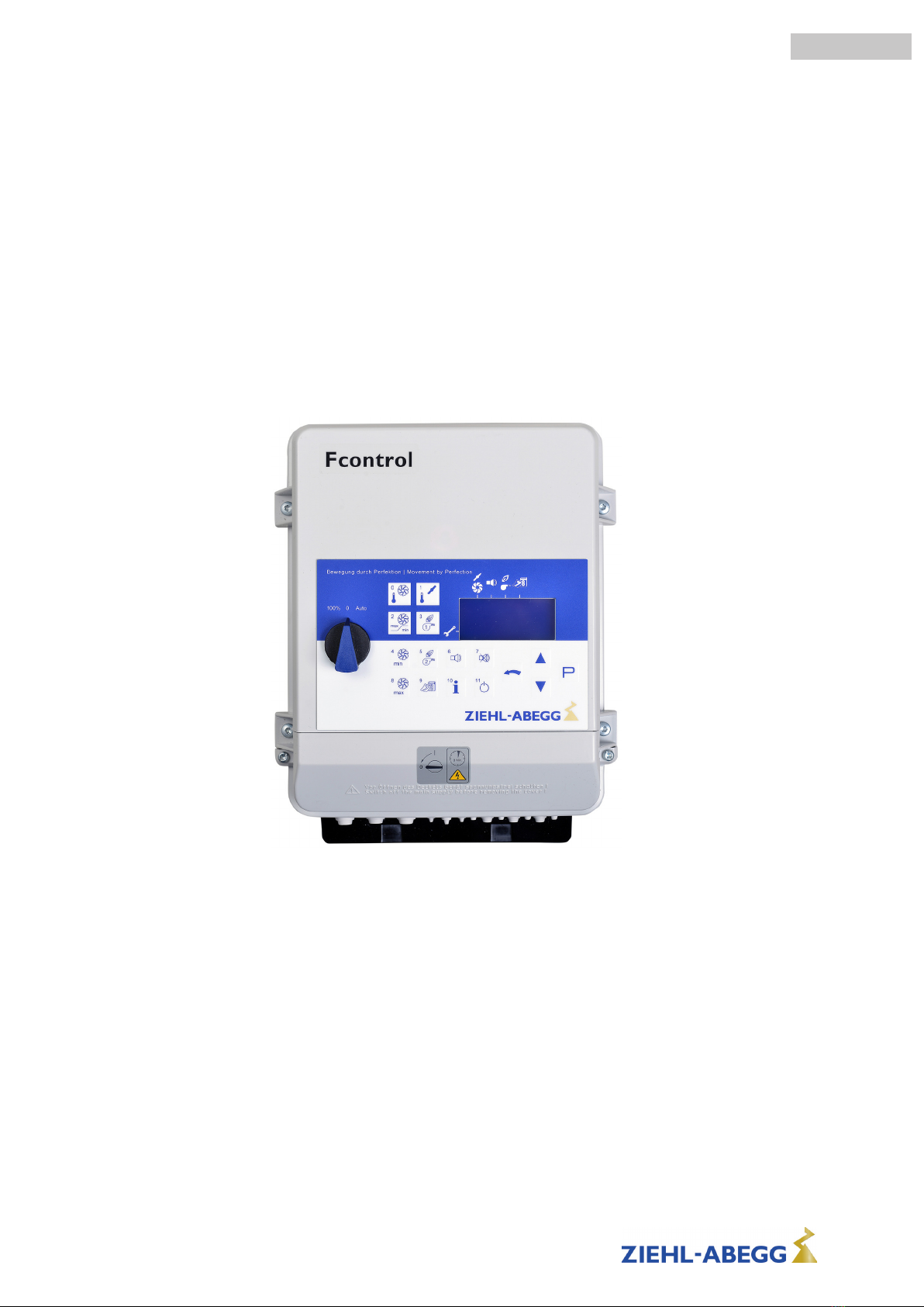
6 Controls and Menu . . . . . . . . . . . . . . . . . . . . . . . . . . . . . . . . . . . . . . . . . . . . . . . . . . . . . . . . . 16
6.1 switches . . . . . . . . . . . . . . . . . . . . . . . . . . . . . . . . . . . . . . . . . . . . . . . . . . . . . . . . . . . . 16
6.2 Multipurpose LC display . . . . . . . . . . . . . . . . . . . . . . . . . . . . . . . . . . . . . . . . . . . . . . . . 17
6.3 Direct selection keys . . . . . . . . . . . . . . . . . . . . . . . . . . . . . . . . . . . . . . . . . . . . . . . . . . 18
6.4 Menu operation . . . . . . . . . . . . . . . . . . . . . . . . . . . . . . . . . . . . . . . . . . . . . . . . . . . . . . 19
6.5 Menu structure . . . . . . . . . . . . . . . . . . . . . . . . . . . . . . . . . . . . . . . . . . . . . . . . . . . . . . . 19
7 The Installation menu . . . . . . . . . . . . . . . . . . . . . . . . . . . . . . . . . . . . . . . . . . . . . . . . . . . . . . 20
7.1
|
Installation
|
Entry . . . . . . . . . . . . . . . . . . . . . . . . . . . . . . . . . . . . . . . . . . . . . . . . . . . . 20
7.2
|
Installation
|
Ventilation . . . . . . . . . . . . . . . . . . . . . . . . . . . . . . . . . . . . . . . . . . . . . . . . 21
7.2.1 Exhaustair rate . . . . . . . . . . . . . . . . . . . . . . . . . . . . . . . . . . . . . . . . . . . . . . . . . 21
7.2.2 Minimum speed cut off . . . . . . . . . . . . . . . . . . . . . . . . . . . . . . . . . . . . . . . . . . . 21
7.2.3 Peak load fans . . . . . . . . . . . . . . . . . . . . . . . . . . . . . . . . . . . . . . . . . . . . . . . . . 22
7.2.3.1 Variant of peak load 1 . . . . . . . . . . . . . . . . . . . . . . . . . . . . . . . . . . . 22
7.2.3.2 Variant of peak load 2 and 3 . . . . . . . . . . . . . . . . . . . . . . . . . . . . . . . 23
7.2.4 humidity control . . . . . . . . . . . . . . . . . . . . . . . . . . . . . . . . . . . . . . . . . . . . . . . . 23
7.3
|
Installation
|
Shutter . . . . . . . . . . . . . . . . . . . . . . . . . . . . . . . . . . . . . . . . . . . . . . . . . . . 24
7.4
|
Installation
|
Heating 1 . . . . . . . . . . . . . . . . . . . . . . . . . . . . . . . . . . . . . . . . . . . . . . . . . 25
7.5
|
Installation
|
Heating 2 . . . . . . . . . . . . . . . . . . . . . . . . . . . . . . . . . . . . . . . . . . . . . . . . . 25
7.5.1 Special function for “piglet nest warm water heating” . . . . . . . . . . . . . . . . . . . . . . . 26
7.6
|
Installation
|
Setpoint derating . . . . . . . . . . . . . . . . . . . . . . . . . . . . . . . . . . . . . . . . . . . 27
7.7
|
Installation
|
Sensor adjust . . . . . . . . . . . . . . . . . . . . . . . . . . . . . . . . . . . . . . . . . . . . . . 28
7.8
|
Installation
|
Heatexchange . . . . . . . . . . . . . . . . . . . . . . . . . . . . . . . . . . . . . . . . . . . . . 29
7.9
|
Installation
|
bypass shutter . . . . . . . . . . . . . . . . . . . . . . . . . . . . . . . . . . . . . . . . . . . . . 30
7.10
|
Installation
|
Exhaust system . . . . . . . . . . . . . . . . . . . . . . . . . . . . . . . . . . . . . . . . . . . . 31
7.10.1 Group control variants . . . . . . . . . . . . . . . . . . . . . . . . . . . . . . . . . . . . . . . . . . . . 33
7.11
|
Installation
|
Bus . . . . . . . . . . . . . . . . . . . . . . . . . . . . . . . . . . . . . . . . . . . . . . . . . . . . . 35
7.11.1 Setting of Bus addresses . . . . . . . . . . . . . . . . . . . . . . . . . . . . . . . . . . . . . . . . . . 37
7.11.2 Operation with only one control unit (Stand-Alone) . . . . . . . . . . . . . . . . . . . . . . . . 37
7.12
|
Installation
|
IO Setup . . . . . . . . . . . . . . . . . . . . . . . . . . . . . . . . . . . . . . . . . . . . . . . . . . 37
7.12.1 Factory setting allocations / possible allocations . . . . . . . . . . . . . . . . . . . . . . . . . . 41
7.13
|
Installation
|
Diverse . . . . . . . . . . . . . . . . . . . . . . . . . . . . . . . . . . . . . . . . . . . . . . . . . . 42
7.13.1 Displaymode . . . . . . . . . . . . . . . . . . . . . . . . . . . . . . . . . . . . . . . . . . . . . . . . . . 42
7.13.2 Switch mode . . . . . . . . . . . . . . . . . . . . . . . . . . . . . . . . . . . . . . . . . . . . . . . . . . 42
7.13.3 Preheat operation, Stall washing Operation . . . . . . . . . . . . . . . . . . . . . . . . . . . . . 42
7.13.4 External switch extension . . . . . . . . . . . . . . . . . . . . . . . . . . . . . . . . . . . . . . . . . 43
7.13.5 Set protection PIN Lock . . . . . . . . . . . . . . . . . . . . . . . . . . . . . . . . . . . . . . . . . 44
7.13.6 Comparison of two sensor values . . . . . . . . . . . . . . . . . . . . . . . . . . . . . . . . . . . . 44
7.13.7 Temperature monitoring by distance alarms (relative to nominal value) . . . . . . . . . . 45
7.14
|
Installation
|
Measuring fan . . . . . . . . . . . . . . . . . . . . . . . . . . . . . . . . . . . . . . . . . . . . . 45
7.14.1 General description of function . . . . . . . . . . . . . . . . . . . . . . . . . . . . . . . . . . . . . . 45
7.14.2 Configuration . . . . . . . . . . . . . . . . . . . . . . . . . . . . . . . . . . . . . . . . . . . . . . . . . . 46
7.15
|
Installation
|
Motorsetup . . . . . . . . . . . . . . . . . . . . . . . . . . . . . . . . . . . . . . . . . . . . . . . . 48
7.15.1 Menu “Motorsetup ” ............................................. 48
7.15.2 Setting motor rated current . . . . . . . . . . . . . . . . . . . . . . . . . . . . . . . . . . . . . . . . 48
7.15.3 Setting motor rated voltage . . . . . . . . . . . . . . . . . . . . . . . . . . . . . . . . . . . . . . . . 49
7.15.4 Adjustment of the U/f curve . . . . . . . . . . . . . . . . . . . . . . . . . . . . . . . . . . . . . . . . 49
7.15.5 Setting for Rampup time and Rampdown time . . . . . . . . . . . . . . . . . . . . . . . . . . . 51
7.15.6 Setting Current limit . . . . . . . . . . . . . . . . . . . . . . . . . . . . . . . . . . . . . . . . . . . . . 51
7.15.7 Setting brake function . . . . . . . . . . . . . . . . . . . . . . . . . . . . . . . . . . . . . . . . . . . . 51
7.15.8 Setting Boost value . . . . . . . . . . . . . . . . . . . . . . . . . . . . . . . . . . . . . . . . . . . . . . 52
7.15.9 Suppression of speeds . . . . . . . . . . . . . . . . . . . . . . . . . . . . . . . . . . . . . . . . . . . 53
7.16
|
Installation
|
Diagnostic . . . . . . . . . . . . . . . . . . . . . . . . . . . . . . . . . . . . . . . . . . . . . . . . 53
8 Commissioning . . . . . . . . . . . . . . . . . . . . . . . . . . . . . . . . . . . . . . . . . . . . . . . . . . . . . . . . . . . 55
8.1 Prerequisites for commissioning . . . . . . . . . . . . . . . . . . . . . . . . . . . . . . . . . . . . . . . . . . 55
8.2 Procedure for commissioning . . . . . . . . . . . . . . . . . . . . . . . . . . . . . . . . . . . . . . . . . . . . 55
Operating Instructions Fcontrol – model series FTET4/6/10AHMQ-L
L-BAL-E139-GB 2022/03 Index 006 Part.-No.
3/92

9 Settings for operation . . . . . . . . . . . . . . . . . . . . . . . . . . . . . . . . . . . . . . . . . . . . . . . . . . . . . . 56
9.1 Menu overview for operation . . . . . . . . . . . . . . . . . . . . . . . . . . . . . . . . . . . . . . . . . . . . 56
9.2 Quick Info . . . . . . . . . . . . . . . . . . . . . . . . . . . . . . . . . . . . . . . . . . . . . . . . . . . . . . . . . . . 56
9.3 Setting Ventilation . . . . . . . . . . . . . . . . . . . . . . . . . . . . . . . . . . . . . . . . . . . . . . . . . . . . . 58
9.3.1 For Control of Ventilation . . . . . . . . . . . . . . . . . . . . . . . . . . . . . . . . . . . . . . . . . . 58
9.3.2 For throttle shutter control . . . . . . . . . . . . . . . . . . . . . . . . . . . . . . . . . . . . . . . . . 59
9.3.3 Setpoint derating . . . . . . . . . . . . . . . . . . . . . . . . . . . . . . . . . . . . . . . . . . . . . . . 60
9.3.4 Special function: Humidity control . . . . . . . . . . . . . . . . . . . . . . . . . . . . . . . . . . . . 61
9.4 Setting temperature monitoring . . . . . . . . . . . . . . . . . . . . . . . . . . . . . . . . . . . . . . . . . . . 63
9.4.1 Example for Alarm Maximum message on stall unit. . . . . . . . . . . . . . . . . . . . . . . . 64
9.4.2 Example for overtemperature message in stall 3 when networking . . . . . . . . . . . . . 65
9.5 Settings for heating . . . . . . . . . . . . . . . . . . . . . . . . . . . . . . . . . . . . . . . . . . . . . . . . . . . 66
9.5.1 Settings for Heating H1 . . . . . . . . . . . . . . . . . . . . . . . . . . . . . . . . . . . . . . . . . . . 66
9.5.1.1 Two-position control independent of the ventilation nominal value (factory
setting) . . . . . . . . . . . . . . . . . . . . . . . . . . . . . . . . . . . . . . . . . . . . . . 66
9.5.1.2 Two-position control independent of the ventilation nominal value . . . . . 67
9.5.1.3 Heating H1 via the 0...10 V signal (linear) . . . . . . . . . . . . . . . . . . . . . 68
9.5.2 Settings for heating H2 (factory setting deactivated) . . . . . . . . . . . . . . . . . . . . . . . 69
9.6 Increase program . . . . . . . . . . . . . . . . . . . . . . . . . . . . . . . . . . . . . . . . . . . . . . . . . . . . . 70
9.6.1 Set the trajectory of the growth curve . . . . . . . . . . . . . . . . . . . . . . . . . . . . . . . . . 70
9.6.2 Curve for Setpoint compartment temperature . . . . . . . . . . . . . . . . . . . . . . . . . . . . 71
9.6.3 Curve for Minimum Ventilation . . . . . . . . . . . . . . . . . . . . . . . . . . . . . . . . . . . . . . 71
9.6.4 Curve for Maximum Ventilation . . . . . . . . . . . . . . . . . . . . . . . . . . . . . . . . . . . . . . 72
9.6.5 Curve for Heating1 . . . . . . . . . . . . . . . . . . . . . . . . . . . . . . . . . . . . . . . . . . . . . . 72
9.6.6 Curve for Heating2 . . . . . . . . . . . . . . . . . . . . . . . . . . . . . . . . . . . . . . . . . . . . . . 72
10 Menu tables . . . . . . . . . . . . . . . . . . . . . . . . . . . . . . . . . . . . . . . . . . . . . . . . . . . . . . . . . . . . . . 73
10.1 Main menu . . . . . . . . . . . . . . . . . . . . . . . . . . . . . . . . . . . . . . . . . . . . . . . . . . . . . . . . . . 73
10.2 Installation menu . . . . . . . . . . . . . . . . . . . . . . . . . . . . . . . . . . . . . . . . . . . . . . . . . . . . . 75
10.3 Programmed outputs and inputs of a system . . . . . . . . . . . . . . . . . . . . . . . . . . . . . . . . 80
11 Malfunctions / trouble shooting . . . . . . . . . . . . . . . . . . . . . . . . . . . . . . . . . . . . . . . . . . . . . . 80
11.1 Fault messages . . . . . . . . . . . . . . . . . . . . . . . . . . . . . . . . . . . . . . . . . . . . . . . . . . . . . . 80
11.2 Behaviour of outputs during operation and faults . . . . . . . . . . . . . . . . . . . . . . . . . . . . . 82
12 Enclosure . . . . . . . . . . . . . . . . . . . . . . . . . . . . . . . . . . . . . . . . . . . . . . . . . . . . . . . . . . . . . . . . 83
12.1 Technical data . . . . . . . . . . . . . . . . . . . . . . . . . . . . . . . . . . . . . . . . . . . . . . . . . . . . . . . 83
12.1.1 Performance reduction during elevated ambient temperatures . . . . . . . . . . . . . . . . 84
12.2 Connection diagram . . . . . . . . . . . . . . . . . . . . . . . . . . . . . . . . . . . . . . . . . . . . . . . . . . . 85
12.3 Dimensions [mm] . . . . . . . . . . . . . . . . . . . . . . . . . . . . . . . . . . . . . . . . . . . . . . . . . . . . . 86
12.4 Application examples . . . . . . . . . . . . . . . . . . . . . . . . . . . . . . . . . . . . . . . . . . . . . . . . . . 87
12.4.1 FTET6/10AHMQ-L: Single exhaust system with 1~ fans . . . . . . . . . . . . . . . . . . . . 87
12.4.2 FTET6/10AHMQ-L: Central exhaust air with activation of group 2 . . . . . . . . . . . . . . 88
12.4.3 FTET6/10AHMQ-L and CTE/AHQ(X)-L: with activation of groups for central exhaust air
89
12.5 Index . . . . . . . . . . . . . . . . . . . . . . . . . . . . . . . . . . . . . . . . . . . . . . . . . . . . . . . . . . . . . . 91
12.6 Manufacturer reference . . . . . . . . . . . . . . . . . . . . . . . . . . . . . . . . . . . . . . . . . . . . . . . . 92
12.7 Service note . . . . . . . . . . . . . . . . . . . . . . . . . . . . . . . . . . . . . . . . . . . . . . . . . . . . . . . . . 92
Operating Instructions Fcontrol – model series FTET4/6/10AHMQ-L
L-BAL-E139-GB 2022/03 Index 006 Part.-No.
4/92

1 General notes
Compliance with the following specifications also serves to ensure product safety. Should the speci-
fied information, in particular with regard to general safety, transportation, storage, assembly, operat-
ing conditions, commissioning, service, maintenance, cleaning and disposal/recycling not be ob-
served, safe operation of the product may not be guaranteed and can potentially pose a risk of death
or injury to users and/or third parties.
For this reason, deviations from the specifications below can lead to the loss of legal materials defect
liability as well as to liability of the buyer for the product rendered unsafe by deviation from the
specifications.
1.1 Meaning of the operating instructions
Before installation and start-up, read this manual carefully to ensure correct use!
We emphasize that these operating instructions apply to specific units only, and are in no way valid for
the complete system!
Use these operating instructions to work safely with and on the device. They contain safety instruc-
tions that must be complied with as well as information that is required for failure-free operation of the
device.
Keep these operating instructions together with the device. It must be ensured that all persons that
are to work on the device can refer to the operating instructions at any time.
Keep the operating instructions for continued use. They must be passed-on to all successive owners,
users and final customers.
1.2 Target group
The operating instructions address persons entrusted with planning, installation, start-up, mainte-
nance and servicing, who have the corresponding qualifications and skills for their job.
1.3 Exclusion of liability
Concurrence between the contents of these operating instructions and the described hardware and
software in the device has been examined. It is still possible that non-compliances exist; no guarantee
is assumed for complete conformity. To allow for future developments, construction methods and
technical data given are subject to alteration. We do not accept any liability for possible errors or
omissions in the information contained in data, illustrations or drawings provided.
ZIEHL-ABEGG SE is not liable for damage due to misuse, incorrect use, improper use or as a
consequence of unauthorized repairs or modifications.
1.4 Copyright
These operating instructions contain copyright protected information. The operating instructions may
be neither completely nor partially photocopied, reproduced, translated or put on data medium without
previous explicit consent from ZIEHL-ABEGG SE. Infringements are liable for damages. All rights
reserved, including those that arise through patent issue or registration on a utility model.
2 Safety instructions
2.1 Intended use
The equipment is to be used solely for the purposes specified and confirmed in the order.
Any other use above and beyond this is considered not for the intended purpose unless agreed
otherwise by contract. The manufacturer will not be liable for any damage resulting from this. The
individual or company using it bears the sole risk.
Reading these operating instructions and complying with all contained instructions - especially the
safety notifications contained therein - are considered part of intended use. To consider is also the
manual of attached components. Not the manufacturer, rather the operator of the device is liable for
any personal harm or material damage arising from non-intended use!
Operating Instructions Fcontrol – model series FTET4/6/10AHMQ-L General notes
L-BAL-E139-GB 2022/03 Index 006 Part.-No.
5/92

2.2 Explanations of symbols
Safety instructions are highlighted with warning triangles and are depicted according to the degree of
hazard as follows.
Attention!
General hazardous area. Death or severe injury or significant property damage can occur if the
corresponding precautions are not taken!
Danger due to electric current
Danger by dangerous, electric voltage! Death or severe injury can occur if the corresponding
precautions are not taken!
Information
Important additional information and advice for user.
2.3 Product safety
The device conforms to the state of the art at the time of delivery and is fundamentally considered to
be reliable. The device and its accessories must only be used in a flawless condition and installed and
operated in compliance with the assembly instructions and/or operating instructions. Operating out-
side the device's technical specifications (see name plate and attachment / technical data) can lead to
a defect in the device and additional damage!
Information
In the case of a malfunction or a failure of the equipment check all functions with alarms in order to
prevent injury to persons or property. Note possibility of back-up operation. If used in intensive animal
environments, any malfunctions in the air supply must be detected as soon as possible to prevent the
development of a life-threatening situation for the animals. The design and installation of the system
must comply with local regulations and directives. In Germany these include DIN VDE 0100, the
animal protection and the keeping of working animals ordinance and the pig-keeping ordinance etc.
Also note the instructions of AEL, DLG, VdS.
2.4 Requirements placed on the personnel / due diligence
Persons entrusted with the planning, installation, commissioning and maintenance and servicing in
connection with the frequency inverter must have the corresponding qualifications and skills for these
jobs.
In addition, they must be knowledgeable about the safety regulations, EU/EC directives, rules for the
prevention of accidents and the corresponding national as well as regional and in-house regulations.
Personnel to be trained or instructed and apprentices are only permitted to work on the device under
the supervision of an experienced person. This also applies to personnel undergoing general training.
Comply with the legal minimum age.
2.5 Start-up and during operation
Attention!
•During commissioning, unexpected and hazardous conditions can arise in the entire installation due
to defective adjustments, defective components or incorrect electrical connections. Remove all
persons and objects from the hazardous area.
•During operation, the device must be closed or installed in a control cabinet. Fuses may only be
replaced by new ones and must not be repaired or bypassed. The data for the maximum line fuse
are to be considered absolutely (see Technical data). Use only fuses specified in schematic
diagrams.
•Any faults detected in the electric system/modules/operating equipment must be corrected
immediately. If these faults are not corrected, the device/system is potentially very dangerous. The
device/system must therefore not be operated when it is faulty.
•Pay attention to smooth, low vibration running of the motor/fan, the appropriate instructions in the
drive documentation must be observed!
Operating Instructions Fcontrol – model series FTET4/6/10AHMQ-L Safety instructions
L-BAL-E139-GB 2022/03 Index 006 Part.-No.
6/92

2.6 Work on the device
Information
Mounting, electrical connection, and start-up operation may only be carried out by an electrical
specialist in accordance with electrotechnical regulations (e.g. EN 50110 or EN 60204)!
Danger due to electric current
•It is forbidden to carry out work on live device parts. The degree of protection for the open device is
IP00! Potentially fatal voltages can be touched directly.
•The safe isolation from the supply must be checked using a two-pole voltage detector.
•Even after disconnecting the mains voltage, life-threatening charges can appear between the
protective ground “PE” and the mains connection.
•The protective earth is conducting high discharge currents (dependent on the switching frequency,
current-source voltage and motor capacity). Earthing in compliance with EN specifications shall
therefore be observed even for testing and trial conditions (EN 50 178, Art. 5.2.11). Without
earthing, dangerous voltages can be present on the motor housing.
Waiting period at least 5 minutes!
•Through use of capacitors, danger of death exists even after switching off the device through
directly touching the energized parts or due to parts that have become energized due to faults.
•It is only permitted to remove the housing cover after waiting for 5 minutes once the line supply
cable has been shut down. Should measurement or adjustment work be unavoidable on the opened
unit while still powered, then this may only be performed by qualified personnel acquainted with the
thereby associated hazards.
Attention!
Even after switching off, dangerous temperatures can still occur in and on the device.
Attention!
Automatically restart after a power failure or mains disconnection!
2.7 Modifications / interventions in the device
Attention!
For reasons of safety, no unauthorized interventions or modifications may be made on the device. All
planned modifications must be authorized by the manufacturer in writing.
Use only genuine spare parts / genuine wearing parts / genuine accessories from ZIEHL-ABEGG.Th-
ese parts were specifically designed for the device. There is no guarantee that parts from non-original
sources are designed and manufactured in correspondence with load and safety requirements.
Parts and optional equipment not supplied by ZIEHL-ABEGG are not approved by ZIEHL-ABEGG for
use.
2.8 Operator’s obligation of diligence
•The contractor or owner must also ensure that the electric systems and equipment are operated
and maintained in accordance with electro-technical regulations.
•The owner is obliged to ensure that the device is operated in perfect working order only.
•The device may only be used as intended.
•You must periodically examine the safety equipment for their properly functioning condition.
•The assembly instructions and/or operating instructions are always readily available at the location
where the device is being used, are complete and are in legible condition.
•These persons are regularly instructed in all applicable questions regarding occupational safety
and environmental protection and are knowledgeable regarding the assembly instructions and/or
operating instructions and, especially, are familiar with the safety instructions contained therein.
•All safety and warning notices attached to the device are never removed and remain legible.
Operating Instructions Fcontrol – model series FTET4/6/10AHMQ-L Safety instructions
L-BAL-E139-GB 2022/03 Index 006 Part.-No.
7/92

2.9 Employment of external personnel
Maintenance and service work are frequently carried out by external employees who often do not
recognize the specific situations and the thus resulting dangers.These persons must be comprehen-
sively informed about the hazards in their area of activity.
You must monitor their working methods in order to intervene in good time if necessary.
3 Product overview
3.1 Operational area
The frequency inverter is designed for a stepless control of fans without additional (electromagnetic)
motor noise.
Temperature controller for stalls in individual or central exhaust air systems.
•In installations with single suction, fans, flaps and heatings are controlled via the outputs.
•In central exhaust installations, these devices are used in combination. The devices controls the
exhaust air flap and the heatings for one ompartment. At the same time the exhaust air volumes of
all the compartments connected are signaled to a Master* . The speed is calculated from the sum
of the exhaust air volumes and the fans connected are readjusted.
In order to be able to network several devices, these are equipped with a bus interface. In this way, for
example, the supply air temperature sensor connected to the Master* can be communicated to all
system users. Fault messages on stall devices are transmitted and displayed as a group fault; in
addition the total exhaust air volume of the ventilation system is determined.
Master*
A device which controls and monitors the bus communication and performs central control functions
3.2 Service work
The device must be checked for soiling and, if necessary, cleaned in periodic intervals.
3.3 Transport
•The device is packed ex factory to suit the transport method previously agreed.
•The device may only be transported in the original packaging.
•Avoid shocks and impacts to the device during the transport.
•During manual handling the human lifting and carrying restrictions must be observed and adhered
to.
3.4 Storage
•The device must be stored in its original packaging in a dry and weather-proof room.
•Avoid exposure to extreme heat and cold.
•Avoid prolonged storage; we recommend a maximum of one year (consult the manufacturer before
starting if stored for longer).
3.5 Disposal / recycling
Disposal must be carried out professionally and in an environmentally friendly way in accordance with
the respective national legal stipulations.
"Separate the materials by type and in an environmentally-friendly way.
"If necessary, commission a specialist company with the waste disposal.
Operating Instructions Fcontrol – model series FTET4/6/10AHMQ-L Product overview
L-BAL-E139-GB 2022/03 Index 006 Part.-No.
8/92

4 Mounting
4.1 General notes
Attention!
The following points must be complied with during the mechanical installation to avoid causing a defect
in the device due to assembly errors or environmental influences:
•Before installation remove the device from the packing and check for any possible shipping
damage! Start-up is not allowed in the case of transport damage!
•At a weight greater than 25 kg for men / 10 kg for women, the fan should be lifted out by two
persons (according to REFA). The values may differ from country to country.
•Wear safety shoes and gloves for handling!
•Assemble the device on a clean and stable base. Do not distort during assembly! Use the
appropriate mounting devices for proper installation of the unit!
•A mounting on vibrating base is not permissible, if no data to the vibration strength is made (see
Technical data)!
•When mounted onto lightweight walls, there must be no impermissibly high vibrations or shock
loads. Any banging shut of doors that are integrated into these lightweight walls, can result in
extremely high shock loads. Therefore, we advise you to decouple the devices from the wall.
•Do not allow drilling chips, screws and other foreign bodies to reach the device interior!
•Maintain the stated minimum clearances to ensure unobstructed cooling- air feed as well as
unobstructed outgoing air discharge (see minimum space requirement)!
•The device should be installed in a location where it will not be disturbed, but at the same time can
be easily accessed!
•Depending on the housing model cut off necessary cable inlets respectively to the cable diameter.
Or alternative use cable inlet for cable glands. Metal sheet housings are supplied with stoppers.
Any cable ducts openings not used must be sealed!
•Care must be taken to avoid direct radiation from the sun!
•The device is designed for vertical installation (bottom cable inlet). A horizontal or reclined installa-
tion is only permissible after technical release of the manufacturer!
•Be sure to observe proper heat dissipation (see Technical data, heat dissipation).
4.2 Minimum space requirement
In order to ensure sufficient ventilation of the device, clearance on all sides of at least 50 mm has to
be maintained to the housing walls, switch cabinet doors, wiring ducts, etc. The same clearance
applies to the installation of several devices next to each other.
When installing several devices on top of each other, the danger of reciprocal heating exists. This
layout is only then permissible when the air suctioned from the upper unit does not become warmer
than the permissible ambient temperature (see Technical data). I.e., a correspondingly larger clear-
ance or thermal shielding is required.
4.3 Outdoor installation
Outdoor installation is possible up to -20 °C when the controller supply is not switched off. Installation
must be protected from the effects of weather as much as possible, including protection from direct
sunlight!
4.4 Installation location for agriculture
When using for animal keeping, do not install the device directly in the stable but in a separate room
with a lower pollutant load. This helps to avoid damages caused by pollutant gases (e.g. ammonia
fumes, hydrogen sulphide fumes).
Operating Instructions Fcontrol – model series FTET4/6/10AHMQ-L Mounting
L-BAL-E139-GB 2022/03 Index 006 Part.-No.
9/92

4.5 Temperature influences during commissioning
Avoid condensation in the controller and functional faults attributable to condensation by storing the
controller at room temperature!
5 Electrical installation
5.1 Safety precautions
Danger due to electric current
•Work on electric components may only be carried out by trained electricians or by persons
instructed in electricity under the supervision of an electrician in accordance with electrical
engineering regulations.
•The 5 electrical safety rules must be observed!
•It is forbidden to carry out work on electrically live parts. Even after disconnection, the dc-link is still
live. Always wait at least 3 minutes.
•Cover neighbouring electrical equipment during installation work.
•Other measures may be necessary to achieve safe electrical isolation.
•A second person must always be present when working on energized parts or lines who
disconnects in case of emergency.
•Electrical equipment must be checked regularly: Loose connections are to be re-tightened and
damaged cables must be replaced immediately.
•Always keep switch cabinets and all electrical supply facilities locked. Access is only allowed for
authorized persons using a key or special tool.
•Operating the device with the housing cover removed is prohibited because energized, exposed
parts are present inside the device. Disregarding this regulation can lead to severe personal injury.
•For metal cable inlets the necessary protective earth connection to the bottom of the housing is
made by screws. The device may only be started up when these screws are fitted properly.
•The required protective earth connection is established using screws between the housing parts in
metal terminal space covers and housing casings. Commissioning is only permissible after these
screws have been properly attached!
•Metal screwed-connections are not permitted in plastic housing parts because there is no potential
equalization.
•The device owner is responsible for the EMC of the entire plant according to the locally applicable
standards.
•Never clean electrical equipment with water or similar liquids.
Information
The respective connections are represented in the enclosure of this Operating Instructions (see
connection diagram)!
5.2 EMC-compatible installation
5.2.1 Motor cable
The applicable standard for interference emissions is EN 61000-6-3. Compliance with this standard is
achieved through the use of an unscreened motor feed cable.
5.2.2 Control cables
Pay attention to sufficient distance from powerlines and motor wires to prevent interferences. The
control cable may not be longer than 30 m. Screened control cables must be used when the cable
length is longer than 20 m. When using a shielded cable connect the shielding to one side only, i.e.
only to the control unit with the protective ground (keep cable short and with as little inductance as
possible!).
Operating Instructions Fcontrol – model series FTET4/6/10AHMQ-L Electrical installation
L-BAL-E139-GB 2022/03 Index 006 Part.-No.
10/92

5.3 Mains connection
5.3.1 Mains voltage
The mains connection is made at the terminals: PE, L1 and N. In this regard, it is essential to ensure
that the mains voltage lies within the allowable tolerance specifications (see technical data and rating
plate affixed to the side).
A connection between two phase conductors is possible for 3 ~ 230 V supply networks.
Attention!
To activate the on current limitation, you must wait at least 90 seconds after switching off the line
voltage before switching back on!
5.3.2 Required quality attributes for the mains voltage
Danger due to electric current
The mains voltage must comply with the EN 50160 quality characteristics and the defined standard
voltages in IEC 60038!
5.3.3 Leakage current, securely attached, protective earth conductor
Danger due to electric current
The maximum leakage current depends on the type of device and the connected mains voltage (see
Technical Data). With regard to fixed connection and the type of PE conductor connection, the
specification for the leakage current must be observed under consideration of the locally valid
standards (for Europe see EN 50178 Section 5.2.11 or 5.3.2.1 etc.).
Minimum cross-section for PE conductor for fixed connection 1.5 mm
2
!
5.4 Systems with residual current protective devices
Whether the use of a residual current protective device (RCD) is necessary or allowed depends on the
design of the low-voltage system on which the device is to be operated.
The assessment whether or which residual current protective device should be used is the responsi-
bility of the system operator or electrician commissioned by it.
Danger due to electric current
When selecting the tripping characteristics of the residual current protective device, the possible
residual current form of the power electronics (system with semiconductors) must be observed in
conjunction with the standards and regulations applicable at the place of use.
Design of the power electronics
•The design of the power electronics corresponds to a frequency inverter with two-pulse bridge
circuit and PFC (power factor correction).
Information
To prevent false tripping due to pulse-like charging currents of the integrated EMC filter, we
recommend a rated differential current of 300 mA for reasons of operational reliability in the case of
fixed connection and use of a residual current protective device.
5.5 Inverter output
5.5.1 Motor connection
The motor leads are connected to the terminals: U1, U2. Several fans can be connected to the
controller-the maximum total current of all motors must not exceed the current rating for the controller.
Change direction of rotation
wiring diagram fan!
Operating Instructions Fcontrol – model series FTET4/6/10AHMQ-L Electrical installation
L-BAL-E139-GB 2022/03 Index 006 Part.-No.
11/92

Information
•It is recommended that a separate motor protection unit be foreseen for each fan.
•For motors with thermistors “TB” e.g. type S-ET10.
5.5.2 Disconnection between controller and motor (repair switch)
Ideally, a repair switch should be installed before the controller (supply line disconnect).
In case of complete shutdown (total load) after the controller this may take place under some circum-
stances at full fan level of the controller. This can lead to an overcurrent protection switch-off.
5.6 Motor protection function for motors with thermostats
The motor can be protected by connecting thermostats “TB”.
Attention!
•If the device is used to control multiple fans, it is strongly recommended that the motor protection
function is not used (bridge TB terminals) and that a separate motor protection unit is used for each
fan (e.g. type S-ET10).
The thermostats for the individual motors should have been connected in series to the terminals “TB
- TB”.
When a connected thermostat is activated (interruption between the two terminals “TB - TB”) the
power component for fan speed control is deactivated. This means that if there is a fault at one
fan, all fans are switched off.
•An outside voltage may never be connected to the terminals “TB”!
•If a bypass circuit is installed, or in the “100 %” position on devices with a main switch, the motor
protection inside the controller has no function. In this case, additional motor monitoring may be
required.
Motor fault
Display during motor fault
The bar graph for ventilation modulation remains in operation.
The control unit with digital and analogue inputs and outputs remains active.
Possibilities for re-starting after the drive has cooled down (terminals “TB” bridged) by:
•Main switch to position “0”
|
STOP
|
and back to position “Auto”.
•By switching the mains voltage off and then on again.
5.7 Analog inputs for sensors
Input E1 for temperature sensors in compartment
•Terminals “E1” / “T1”for TF.. (KTY81-210) or PT1000
•1 x Sensor type TFR (Part.-No. 00089846) in scope of delivery
Input E2 (function programable)
•Terminals “E2” / “T2”for TF.. (KTY81-210) or PT1000, sensor not in scope of delivery
–For example for measuring the supply air temperature in single devices or for networking only on
the “Master” device. When networked, the supply air temperature is transferred via bus from the
“Master” to the other devices.
–For example temperature sensor for controlling the heater or shutter independently of the sensor
in the stall (separate control circuit).
•Terminals “E2” / “GND” for humidity sensor with 0 - 10 signal, sensor not in scope of delivery
–Humidity sensor type MFTG-100V item no. 384046 (see humidity control)
Input E3 (function programable)
•Terminals “E3” / “GND” for TF.. (KTY81-210), sensor not in scope of delivery
•For example for measuring the supply air temperature in single devices or for networking only on
the “Master” device. When networked, the supply air temperature is transferred via bus from the
“Master” to the other devices.
•For example temperature sensor for controlling the heater or shutter independently of the sensor in
the stall (separate control circuit).
Operating Instructions Fcontrol – model series FTET4/6/10AHMQ-L Electrical installation
L-BAL-E139-GB 2022/03 Index 006 Part.-No.
12/92

Attention!
•For a high interference immunity a capacitor must be connected directly to the sensor (1nF parallel).
With ZIEHL-ABEGG temperature sensors type TF.. (KTY81-210) a capacitor is integrated.
•Never apply line voltage to analog inputs!
5.8 Control output 0 - 10 V (A1, A2, A3)
The device has three 0 - 10 V outputs:
Output Terminals Factory-programmed function
Installation menu -> IO Setup
output 1 A1 / GND A1 Function:
|
0
|
Ventilation
A1 Invert: OFF
e.g. for exhaust air vent in cot for central exhaust air systems
output 2 A2 / GND A2 Function:
|
2
|
Shutter
A2 Invert: ON
e.g. for throttle shutter behind the extractor fan in cot inverted as factory
setting (10 V to 0 V) i.e.: 10 V shutter CLOSED, 0 V shutter OPEN.
output 3 A3 / GND A3 function:
|
1
|
Heating
A3 Invert: OFF
e.g. for Heating
Information
•It is not permissible to connect outputs of several devices to each other!
•Max. load of 0 - 10 V outputs
Technical data and connection diagram.
•Inverting of outputs, specification of curve points (e.g. for non-linear characteristic curves)
Installation menu -> IO Setup.
•The behaviour of the control outputs at switch position “0” and “100%” must be observed
Chapter
“Switches”.
5.9 Voltage supply for external devices (+24V, GND)
A voltage supply is integrated for external devices e.g. a sensor (max. current load see technical
data).
In case of overload or short circuit (24 V – GND), the external power supply is shut down (multi-fuse).
The device performs a “Reset” and continues operation.
•It is not permissible to connect voltage outputs of several devices to each other!
•It is not permissible to connect voltage outputs in the device to each other!
5.10 Relay outputs (K1, K2, K3)
The device has three relay outputs:
Output Terminals Factory-programmed function
Installation menu -> IO Setup
K 1 11, 14, 12 K1 Function:
|
3
|
Fault
K1 Invert: OFF
•For operation the relay is energized i.e. terminals “11” and “14” are
bridged (factory setting not inverted).
•In the event of a power failure, failure of the internal voltage supply, or a
temperature or fan fault, the alarm relay at the relevant cot controller
drops out and terminals “11” and “12” are bridged. The “master” device
identifies a fault on a member via the data connection; i.e. if a member
has a fault, the fault relay in the master device also drops out. Based on
this function, the fault relay of the “slave” devices can be allocated
different functions if necessary.
•The fault message via the relay can be acknowledged with the “ESC”k-
ault persists (e.g. sensor break) a message is received again
after the adjustable time span “Alarm Pause” (factory setting 60
minutes).
The error message is not to be layed in the same cable as the bus line.
Operating Instructions Fcontrol – model series FTET4/6/10AHMQ-L Electrical installation
L-BAL-E139-GB 2022/03 Index 006 Part.-No.
13/92

K2 21, 24, 22 K2 function:
|
1
|
Heating 1
K2 Invert: OFF
K 3 31, 34, 32 K3 Function:
|
4
|
Peak load ON/OFF
K3 Invert: OFF
Terminals “31” and “32” can be used to switch on the second fan.
Activation must be performed in “Installation” - “Ventilation” (Peak load).
Information
Max. contact load
Technical data and connection diagram.
Inverting the relay outputs and activatable antiblock
Installation menu -> IO Setup.
5.11 Communication
5.11.1 Networking via MODBUS
The device comes equipped with a RS-485 interface for networking via MODBUS. Conntection at: “A
(D+)”, “B (D-)” and “GND”.
A maximum of 32 network users can be connected to the data bus. One of these devices is the
Master.
The Master always has the address 1(display of address in installation menu:- - - - -).
The address must be set in the “Bus”menu. The sensor for the supply air and the group fault must be
connected at the “Master” device!
5.11.2 RS-485 - network design and interface parameter
Please ensure the correct connection; i.e. "A (D+)" must always be connected to "A (D+)" of the next
devices. The same applies to "B (D-)" .
In addition, a "GND" connection must be established, as dissimilar potential (over 10 V!) will lead to
the destruction of the RS-485 interface (e.g. lightning).
general example for MODBUS device connection
The data line must be connected from one device to the next. No other type of wiring is allowed!
Always use only two wires of one lead (twisted pair) for the connection.
MODBUS
26.02.2007
v_modbus_verbindung.vsd
Example for MODBUS connection
Recommended wire types
1. CAT5 / CAT7 cables
2. J-Y (St) 2x2x0.6 (telephone cable)
3. AWG22 (2x2 twisted pair)
When using telephone cable with four cable cores, we recommend the following allocation:
“A (D+)” red, “B (D-)” black, “GND” white
Operating Instructions Fcontrol – model series FTET4/6/10AHMQ-L Electrical installation
L-BAL-E139-GB 2022/03 Index 006 Part.-No.
14/92

Information
•Pay attention to sufficient distance from powerlines and motor wires (min. 20 cm).
•Except the data link "A (D+)", "B (D-)" and "GND"- connection may no further cable cores of the data
line be used.
•Max allowed wire length 1000 m (CAT5/7 500 m).
Shielding
The use of shielded cables is normally not needed but offers high protection against electromagnetic
interferences, especially high frequencies. However, the effectiveness of the shield depends on care-
ful installation of the line.
If shielded cables are used, the shield should be placed at “PE” on at least one side (preferably on the
master connection). The occurrence of compensating currents may have to be considered if the shield
is contacted on both sides.
Shield connection correct Shield connection incorrect
Default interface parameter
Baudrate 19200
Bits 8
Parity Even (None, exception of devices agriculture)
Stop bits 1
Handshake none
Information
If any matters are unclear, please contact our V-STE support department for control systems -
ventilation technology. The information sheet "Network structure of MODBUS" R-TIL08_01 contains
detailed information about "MODBUS".
5.12 Potential at control voltage connections
The connections for the control voltage (< 30 V) relate to the common GND potential (exception: relay
contacts are potential-free). There is a potential isolation between the connections for the control
voltage and the PE conductor. It must be ensured that the maximum external voltage at the con-
nections for the control voltage cannot exceed 30 V (between the “GND” and “PE” conductor
terminals). A connection to the PE conductor potential can be made if required; fit a bridge between
the “GND” terminal and the “PE” connection (terminal for shield).
Operating Instructions Fcontrol – model series FTET4/6/10AHMQ-L Electrical installation
L-BAL-E139-GB 2022/03 Index 006 Part.-No.
15/92

6 Controls and Menu
6.1 switches
0Power stack (fan) is switched off
Auto Power stack in operation (standard position)
100 % Ventilators are operated directly from the mains with no control.
Motor protection by thermostat connection input “TB” without function!
The display is in operation in every switch position! (cannot be switched off)!
The function of the switch for the control unit can be changed in the Installation menu.
“Diverse” - “Switch mode”
Switch mode “OFF” (Factory setting)
•The control unit is active in all switch positions.
–Overtemperature/undertemperature messages, shutter control, etc. also in switch position “0” and “100%”.
–Messages in the case of a motor fault (interruption at “TB” terminals) and at the digital inputs for “ALARM fan” (function
1D) and “ALARM ZR fan” (function 7D) also in switch position “0” and “100%”.
Attention!
The exhaust air vent at “A2” is not directly influenced by the switch position “0” or “100%” (the control
unit remains in a constant active state).
Switch mode “ON”
•In switch position “0” and “100%” the control unit is switched off and behaves passively (stop symbol in display).
–Messages at overtemperature and undertemperature via display and relay “K1” are switched off.
–Messages in the case of a motor fault (interruption at “TB” terminals) and at digital inputs “D1” and “D2” for “ALARM ZR
fan” (function 7D) also in switch position “0” and “100%”.
–Messages at digital inputs “D1” and “D2” for “ALARM fan” (function 1D) are switched off.
–The heating via relay (K2) and output 0...10 V (A3) is switched off.
–The exhaust air vent via output 0 to 10 V (A2) is closed (if A2 inverted as factory setting 10 V, if A2 not inverted 0 V).
Attention!
If the switch mode is “ON” and the device is in good order, in main switch position “0” and “100%” the
exhaust air vent at “A2” is closed (10 V). Therefore, it must be ensured that the shutter is fully
opened for switch position “100%”.
I.e. with inverted activation (A2: 0 V shutter OPEN, A2: 10 V shutter CLOSED), the control signal
for the shutter must be interrupted via a suitable switch.
The voltage supply for operation of the throttle actuator motor must be maintained.
Operating Instructions Fcontrol – model series FTET4/6/10AHMQ-L Controls and Menu
L-BAL-E139-GB 2022/03 Index 006 Part.-No.
16/92

6.2 Multipurpose LC display
The following display appears after switching on (Reset) or after approx. 15 minutes without pressing
a key. This display shows a list of the most important values and statuses of the control functions and
is the starting point (Start) for the operation.
Overview display
23.05.2011
v_display_erkl_ftet_l.vsd
4
5
10
11
2
6
9
121
ESC
3
7 8
1. S: active set value
2. Numeric display 5 digit
3. Current derating active
4. Alarm-Symbol (fault indication)
5. Brake motor active
6. Fire symbol Heating is activated
7. temperature managment active (power reduction)
8. Lowering function activ
9. STOP symbol (main switch “0” - “100 %”)
10. Bar symbols ventilation modulation (corresponds to output “A1”)
11. Text line 3 figures (display unit, etc.)
12. KL: Opening exhaust air flap [%] <-> F: Output frequency [Hz]
PProgram key and open menu
▲Menu selection, increase value
▼Menu selection, reduce value
ESC Escape leave menu
* Factory set display for “shutter”, alternatively other values
Installation Various / Display Mode.
In case of an alarm, the display overview changes together with the alarm message. It can be confirmed by pressing the Alarm
Off“ key ”7
|
(approx. 3
|
sec.) I.e. the malfunction ndication via he display and via the relay is switched off (
Alarm functions).
S:25°C SH:99%
Operating Instructions Fcontrol – model series FTET4/6/10AHMQ-L Controls and Menu
L-BAL-E139-GB 2022/03 Index 006 Part.-No.
17/92

6.3 Direct selection keys
The device is equipped with direct selection keys for simple operation. In addition to the menu-guided
operation with the four keys (ESC, ▲, ▼and P) some settings can be selected directly with the symbol
keys 0 -11.
Key Display after press-
ing
Function Description
Settings for op-
eration under:
0
Setpoint
Setpoint Ventilation Setting Ventilation
For Control of Ventilation
1
Shutter offset
Offset (nominal value) for throttle
shutter
Setting Ventilation
For throttle shutter control
2
Pband
Pband Ventilation Setting Ventilation
For Control of Ventilation
3
H1 Offset
Offset (nominal value) for heater
H1
Settings for heating1
4
Min. ventilation
Minimum ventilation Setting Ventilation
For Control of Ventilation
5
H2 Setpoint
Offset (nominal value) for heater
H2
Settings for heating2
6
Alarm Maximum
Setting an absolute temperature
maximum.
Setting temperature monitoring
Example for Alarm Maximum mes-
sage on stall unit.
7 Acknowledgement with alarm mes-
sage
8
Max. ventilation
Maximum ventilation Setting Ventilation
For Control of Ventilation
9
Actual day
Setting the program day Also
serves to reset the program to the
beginning (day 0)
Increase program
Set the trajectory of the growth
curve
10
S:20.0° SH:94%
Info key
Directly to the display overview
from every menu
11
Stall on
Stall on
Stall off
Cot Preheating
Cot Washing
Quick Info
Operating Instructions Fcontrol – model series FTET4/6/10AHMQ-L Controls and Menu
L-BAL-E139-GB 2022/03 Index 006 Part.-No.
18/92

6.4 Menu operation
The menu group is selected starting from the
Overview display. To the right with the UP key
▲, to the left with the DOWN key ▼.
The triangle shows the menu group, for “Ven-
tilation”, for example, this is underneath the
symbol for fan and shutter.
By pushing the P button, one reaches individu-
al menu items in the menu group (e.g. to “PIN”,
“Setpoint” etc.).
One moves up and down within the menu
group using the arrow keys.
To make adjustments, press the P key after
selecting the menu item. If the previously set
value starts to flash, it can be adjusted with the
▼ + ▲ keys and then saved with the P key.
To exit the menu without making any changes,
use the
|
Esc
|
key, i.e., the originally set values
remain.
One returns to the level menu group “Ventila-
tion” using the
|
ESC
|
key.
Overview display
▲
▼
▲
▼
S:20.0° SH:94%
Ventilation
↑
|
ESC
|
P ↓
↑
|
ESC
|
P ↓
PIN
Setpoint
▼ ▲ ▼ ▲
Setpoint
Pband
6.5 Menu structure
Overview display ▲
▼
▲
▼
▲
▼
▲
▼
S:20.0° SH:94%
Ventilation
Alarm
Heating1
Day of program
↑
|
ESC
|
P ↓
↑
|
ESC
|
P ↓
↑
|
ESC
|
P ↓
↑
|
ESC
|
P ↓
↑
|
ESC
|
P ↓
PIN
Setpoint
Cot ON/OFF
Freshairtemp.
Temp. Min. Value
Temp. Max. Value
Language
etc.
Ventilation Fan +
Shutter
Alarm Overtemper-
ature + Undertemper-
ature
Heating via relay or
0 - 10 V
Increase curves
Operating Instructions Fcontrol – model series FTET4/6/10AHMQ-L Controls and Menu
L-BAL-E139-GB 2022/03 Index 006 Part.-No.
19/92

7 The Installation menu
7.1
|
Installation
|
Entry
Attention!
The settings in the installation menu are priority basic settings that must be made during start-up
operation. Make these settings only if you have an exact understanding of the device functions and
system functions. Subsequent modifications must be coordinated with your electrician. We are never
liable for damage or harm caused by improper operation or insufficient knowledge.
To protect the settings in the Installation menu against unauthorised manipulation, the PIN
|
1070
|
must be entered.
Overview display
S:20.0° SH:94%
Procedure:
1. Press the P-key when in the overview to show the “PIN” menu item.
2. Press the P-key, the first digit “0” flashes.
3. Set the first digit to “1” with the keys and confirm with the P-key.
4. Enter the other digits etc. until PIN
|
1070
|
is complete.
5. The “Installation” menu is opened, (the triangle points to the tool icon Installation).
6. Press the P key, the first menu group “Ventilation” appears in the Installation menu.
Once this menu is open, the PIN-Protection is no longer active for approx. 15 minutes after
the last key confirmation.
Otherwise the operation in the Installation menu does not differ from that of the other menus.
To exit the installation menu, press the key
|
Esc
|
.
↑
|
ESC
|
P
↓
PIN
PIN
◄Installation
◄Ventilation
Overview menu groups for Installation
▲
▼
▲
▼
▲
▼
▲
▼
▲
▼
Ventilation Shutter Heating1 Heating2 Setp. Derating
▲
▼
▲
▼
▲
▼
▲
▼
▲
▼
Sensor adjust Heatexchange Freshairshutter Exhaust system Bus
▲
▼
▲
▼
▲
▼
▲
▼
IO Setup Diverse Measuring fan * Motor Setup Diagnostic
* The measuring fan menu group only appears if it is activated in the IO Setup (function 4D for digital input D1 operation with
measuring fan).
Operating Instructions Fcontrol – model series FTET4/6/10AHMQ-L The Installation menu
L-BAL-E139-GB 2022/03 Index 006 Part.-No.
20/92
This manual suits for next models
2
Table of contents
Other ZIEHL-ABEGG Desktop manuals