Zip FlushMaster 40090 Manual

87100 v1.12 09.22 FlushMaster Page 1 of 12
Installation instructions & user manual
Zip FlushMaster
Surface-mounted sensor
Water-saver urinal flushing system
Product code: 40090

Page 2 of 12 87100 v1.12 09.22 FlushMaster
!
Contents
Warnings
Warnings......................................................................................2
Key features .................................................................................3
Parts & accessories .......................................................................3
1. Set up water discharge............................................................. 4
2. Install sensor............................................................................ 6
3. Connect latching valve to sensor .............................................7
4. Connect power pack (optional) ............................................. 8
5. Set timing using switches ........................................................ 8
6. Set fill timing using Fill Time Button........................................ 9
7. Complete installation............................................................... 9
Maintenance .............................................................................. 10
Cleaning .....................................................................................10
Battery Replacement..................................................................10
Valve Diaphragm Replacement..................................................10
Troubleshooting.......................................................................... 11
Read all instructions before attempting to install this system.
Never attempt to install this system without reading all instructions.
Designed for indoor use only. Do not expose to the elements of nature.
All plumbing connections must be made in accordance with AS/NZS3500
and installation with AS/NZS3500.2

87100 v1.12 09.22 FlushMaster Page 3 of 12
The world’s most effective urinal flushing system.
Choice of surface-mounted or ceiling recessed sensors.
Battery-operated for simple, inexpensive installation.
Optional power pack for connection to 220 - 240 V, AC power.
Operating pressure 350 - 700 kPa
Variable flush cycle to meet your needs precisely.
Zip FlushMaster WS002 (Product Code 40090)
Surface mounted sensor with latching valve, 6V battery and brass fittings
with Restrictaflow
Spares and accessories:
99021 - Zip FlushMaster Cistern Autosyphon 1.00 inch BSP/ 25 mm
99022 - Zip FlushMaster Cistern Autosyphon 1.25 inch BSP/ 32 mm
99023 - Zip FlushMaster Cistern Autosyphon 1.50 inch BSP/ 38 mm
99024 - Zip FlushMaster Direct Injection Airbreak 1.00 inch BSP / 25 mm
99025 - Zip FlushMaster Direct Injection Airbreak 1.25 inch BSP/ 32 mm
99026 - Zip FlushMaster Direct Injection Airbreak 1.50 inch BSP/ 38 mm
99031 - Zip FlushMaster Power Pack for WS002
90281 - Latching valve and brass fittings with Restrictaflow
99039 - Restrictaflow restrictor (1.9mm)
Fixing
bracket
Key features
Parts & accessories

Page 4 of 12 87100 v1.12 09.22 FlushMaster
Single stall
1.5 to 2.5 Litre
Discharge Capacity
Twin stall
3.0 to 5.0 Litre
Discharge Capacity
Triple stall
4.0 to 7.5 Litre
Discharge Capacity
Single
stall
Twin
stall
Single trough
Maximum trough
length 600 mm
Single trough
1.5 to 2.5 litre
discharge capacity
Single trough
3.0 to 5.0 litre
discharge capacity
Single trough
4.0 to 7.5 litre
discharge capacity
Typical Installation with Cistern
Typical Installation with Direct Injection
Installation
1. Set up water discharge
Twin trough
Maximum trough
length 1200 mm

87100 v1.12 09.22 FlushMaster Page 5 of 12
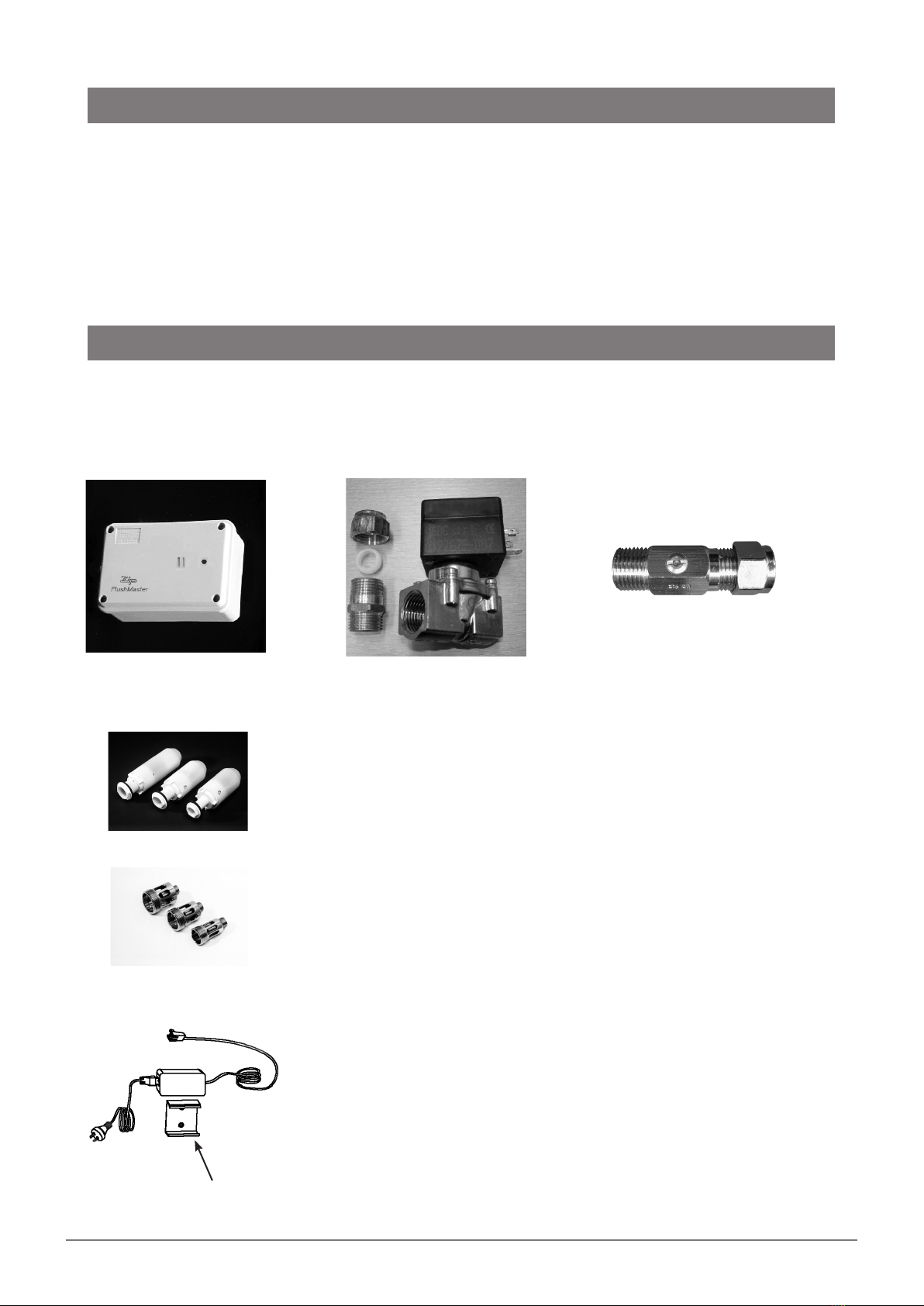
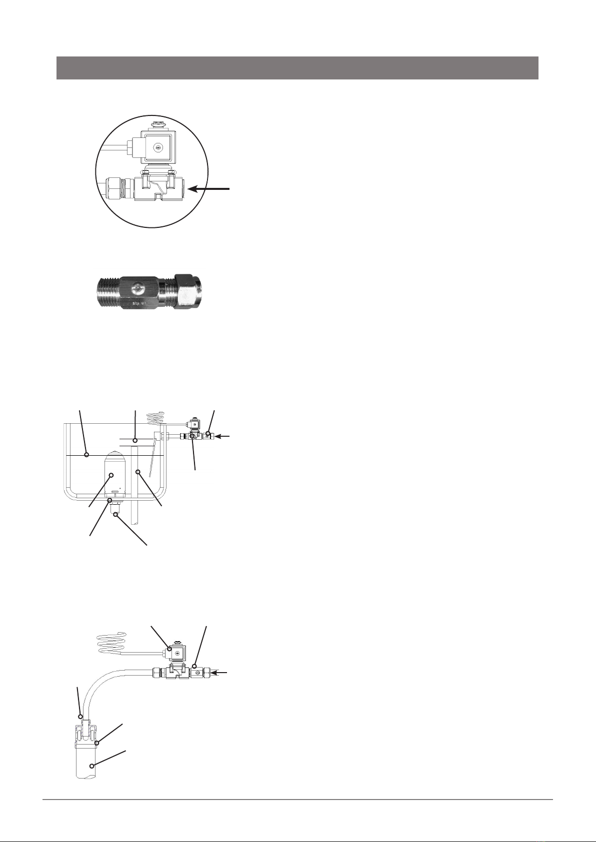
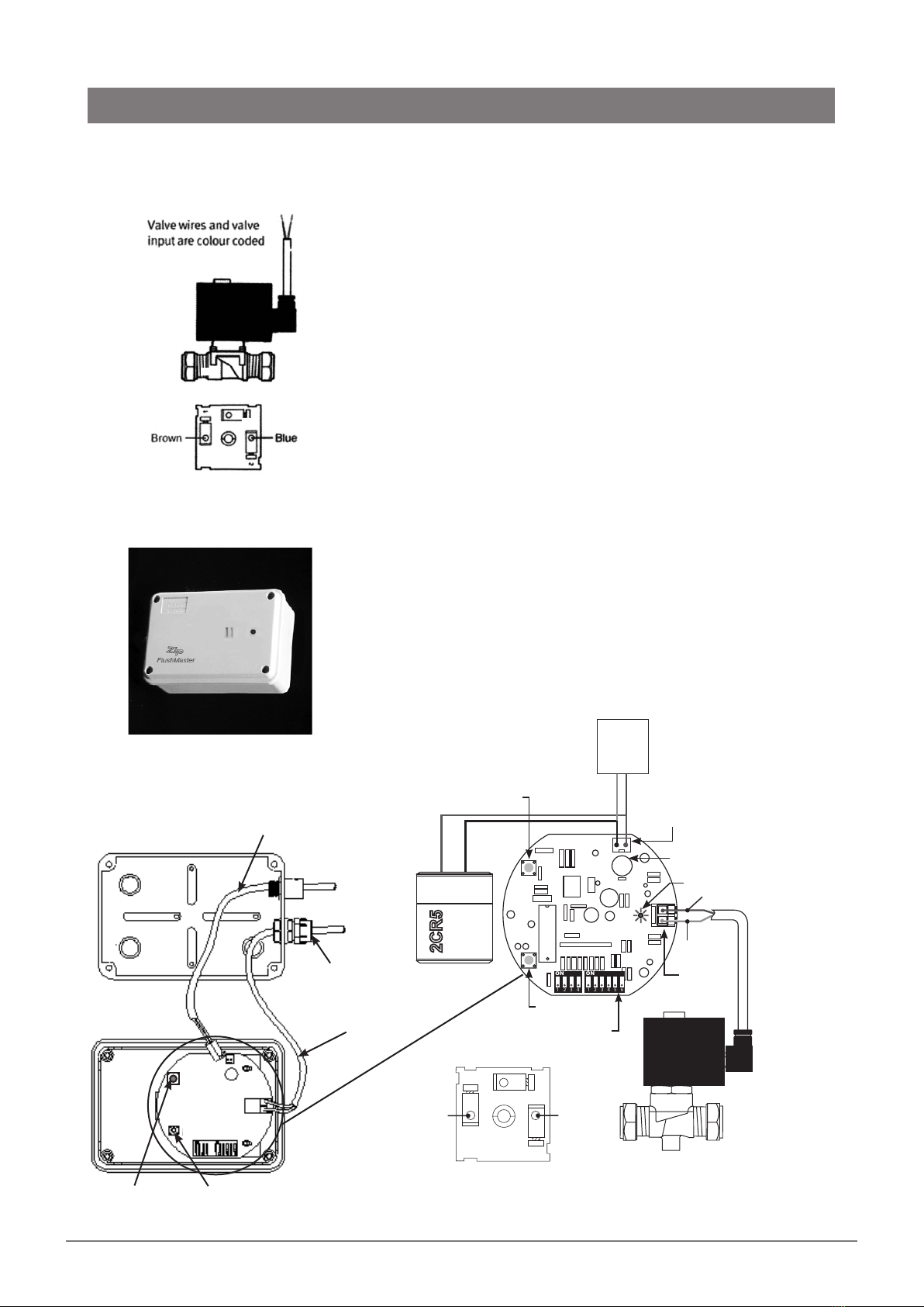
Latching valve (solenoid)
Turn off the mains water supply. An isolating valve must be
supplied and installed in accordance with AS/NZS3500.
Position the latching valve as near to the cistern as possible,
and preferably upright, as shown in the diagram.
Cut the supply pipe and purge any debris or swarf.
Fit the latching valve (15mm OD), ensuring correct flow
direction.
Restrictor installation
The Restrictaflow is designed to save water and to reduce the
flow, particularly when used on single stall installations. The
Restrictaflow is normally required with operating pressures
greater than 700kPa.
Fit the Restrictaflow between the isolating valve and the
latching valve.
The Restrictaflow may be drilled out (in 0.5mm increments)
or removed, when servicing multiple stalls and a higher flow
is required, or when there is insufficient water pressure.
Autosyphon Installation
• More than one cistern can be fed from a single latching
valve, but for accurate balancing, do not connect together
more than two cisterns.
• The balance of water can be achieved by keeping the
supply pipe length to each cistern as equal in length as
possible.
• If this is not practical, fit a flow restrictor of equal rating at
the entry to each cistern.
• Remove the existing filling mechanism from the cistern,
including the float and aspirin washer, to permit
unrestricted inlet of the water. The flow of water into the
cistern is controlled by the latching valve.
• Remove the existing manual flushing mechanism from the
cistern, and fit the syphon to the outlet hole as shown in
the diagram. Connect the sparge pipe to the protruding
thread from the syphon.
• To adjust the auto syphon height within the cistern, add
a second locking nut to the inside of the cistern and wind
the second nut up or down.
• Adjust the height of the syphon so that the flush
triggering level remains below the level of the cistern
overflow pipe.
• An air gap must always remain between the cistern water
level and the inlet water pipe level, to prevent backflow.
Airbreak Installation
• The air break must be fitted in a vertical position. Fitting in
a position other than vertical will result in leakage.
Latching
valve
INOUT Water
Flow
Installation
Water level
Auto
syphon
Outlet
hole
Sparge
pipe
Overflow
pipe
Air gap
water
flow
Restrictaflow
(if required)
Latching
valve
Latching
valve
Air break
fitting
Sparge
pipe
Must be
vertical
water
flow
Restrictaflow
(if required)

Page 6 of 12 87100 v1.12 09.22 FlushMaster
Sensor coverage from a 2700 mm ceiling is approximately 2400 x 3600 mm.
• For a single stall urinal, position the sensor above the centre of the stall.
Position the sensor slots at right angles to the urinal wall.
• For a double stall urinal, position the sensor midway between the stalls.
Position the sensor slots at right angles to the urinal wall.
• For a triple stall urinal, position the sensor above the centre of all three stalls.
Position the sensor slots parallel to the urinal wall.
• For more than three stalls, use additional sensors.
Avoid locating the sensor near heat sources (e.g. hot pipes, radiators, etc) or where direct sunlight may
fall upon the sensor lens slots.
To install the surface mounted sensor, remove the top of the sensor housing and fasten the base of the
sensor housing to the ceiling with screws and/or plugs (not provided).
If any of the cable connecting the sensor to the latching valve is visible, shield it with conduit.
Warning: Do not connect battery or power pack until all plumbing connections are completed. The
power must be connected last as connection activates the system test mode (see page 8).
Typical Installation with Surface Mounted Sensor (Model WS002)
One or two stalls
3600
mm
2400 mm
1200 mm
Two or three stalls
< 500
mm
Ceiling
Sensor
Sensor
Slots
3600 mm
1800 mm
2400
mm
Installation
2. Install sensor
Ceiling
Sensor
Sensor
Slots
Urinal wall
surface
Urinal wall
surface
< 500
mm
• Fit the air break to the top of the urinal sparge pipe (in place of a cistern), as shown in the diagram.
• Do not use sealing tape in the joints. Both the air break and the latching valve use compression
connections fittings. Sealing tape is not required.
• Supply and install a half-inch pipe from the top of the air break, to the outlet side of the latching valve.
• Securely fix the piping to the wall as per AS/NZS3500 to prevent possible tampering and vandalism.
• Adjust the timing of the flush to ensure an adequate flush, by setting the flush cycle switches on the
sensor (see page 9).

87100 v1.12 09.22 FlushMaster Page 7 of 12
1
2
1 1
ON ON
2 23 3 5
4 4 6
Fill Time button
Mains option
F1.6A fuse (Buss)
Fit battery plug
to this input
Fill LED pulses when
fill switch is held down
Battery option
Valve connector
Brown Blue
Control sensors
Reset button
Brown
Blue
Latching
valve
output
Power
Supply
Unit
Cable from
latching valve
Reset
button
3. Connect latching valve to sensor
Run the latching valve cable to the sensor in conduit or within the
building wall and ceiling.
Do not extend the cable as this will affect correct operation.
To fasten the latching valve cable to the circuit board, first remove
the valve output connector on the circuit board by lifting it directly
upwards. Hold the connector so that the fixing screws are facing
you.
Secure the brown cable into the right hand screw terminal and
tighten.
Secure the blue cable into the left hand screw terminal and tighten.
Push the connector back into the socket on the circuit board,
positioned so screws face towards the centre of the board.
In case of repairs or replacement, to detach the latching valve cable
from the circuit board, lift it directly upwards.
Finally, insert the cable from the battery pack into the circuit board
inlet socket.
Once the power is connected, the system operates in test mode.
Note: Always press the RESET button after reconnecting power
to the PCB.
From power
source
Cable gland
(not supplied)
2 1
Installation
Fill Time
Button

Page 8 of 12 87100 v1.12 09.22 FlushMaster
4. Connect power pack (optional)
Locate battery holder and battery supplied with the system.
If connected, remove the battery cable plug from the circuit board.
Connect power pack to 220-240 volt 10 amp AC power point.
Carefully align the power pack outlet cable plug to circuit board
inlet socket.
Firmly insert the cable plug from the power pack into the inlet
socket.
Connect to
circuit board
Fixing
bracket
(supplied)
Connect to
power point
Installation
Surface Mounted Sensor
Drill a 12 mm hole in the side of the box, fit cable gland and thread
cable through the cable gland into the sensor as shown.
5. Set timing using switches
(alternatively, set the timing using fill time button as detailed in step 6)
Test Mode
When all switches are OFF, the sensor defaults to Test mode.
The default test mode is set at approximately 35 seconds delay, 5
seconds flush.
Test mode timings may be adjusted using the Fill Time button
(see next section), otherwise you may reset the timing using the
switches.
Delay time (valve closed)
The delay time is set with any combination of the four switches
turned ON.
The minimum flush delay is 45 seconds (all switches OFF); maximum
flush delay is 15 minutes (all switches ‘on’, 1+2+4+8 minutes).
Setting a short flush delay will reduce the life of the battery.
Valve open time
The ‘valve open’ or ‘flush and fill’ time period can be set with six
switches ranging from 15 seconds to 8 minutes. The total time
ranges from 5 seconds (all switches OFF), to 15.75 minutes (all
switches ON).
If the installation contains a cistern: set the ON period to permit
the cistern to fill, activate the syphon and flush. The fill cycle should
over-run the flush by a few seconds if possible to allow for pressure
fluctuation.
If the installation has no cistern: a direct injection type air break
must be used. Set the ‘valve open’ time to allow an adequate flush
of the urinal whilst observing the flushing volume requirements of
AS3500.1.
Delay time
Switch Time
1 1 minute
2 2 minute
3 4 minute
4 8 minute
Valve open duration
Switch Time
1 15 seconds
2 30 seconds
3 1 minute
4 2 minute
5 4 minute
6 8 minute

87100 v1.12 09.22 FlushMaster Page 9 of 12
6. Set fill timing using Fill Time Button
(alternatively, set the timing using switches as detailed in step 5)
To establish the time, start with an empty cistern.
The board will run Test Mode defaults (approximately 35 seconds
delay, 5 seconds flush) until the time values have been set up.
Time values may be set individually at any time except while the
valve is open.
To set the valve open (flush/fill) time:
• Press the Fill Time Button until the Fill LED lights up.
• Press the Fill Time Button again to make the Fill LED pulse every
second.
• Wait for the desired valve open time to allow the cistern to fill
and flush, then press the Fill Time Button again to set the Fill
Time. If the Fill Time Button is not pressed again, the timer will
be set to 15 minutes.
• The valve will then shut.
7. Complete installation
On completion, fit the cover and tighten the 4 fixing screws.
Installation
Fill Time
Button Fill LED
Reset
button

Page 10 of 12 87100 v1.12 09.22 FlushMaster
Cleaning
Keep the two slot openings in the face of the sensor clear of dirt.
Never clean the case with strong or abrasive cleaners.
Wipe with a soft cloth, warm water and dish washing liquid.
Never hose or spray any part of the flushing system.
Where the Zip FlushMaster is powered by a long life lithium
battery a life of up to three years can be anticipated depending on
frequency of activation.
However to avoid the inconvenience associated with any
malfunction of the flushing system, it is recommended that both
the battery and the latching valve diaphragm be replaced annually.
Where the optional power pack is fitted, the power must be
turned off at the power point before any form of maintenance is
attempted.
Battery Replacement
Remove protective cover from sensor housing, locate battery
holder.
Remove cover from battery holder and remove existing battery.
Replace existing battery with lithium cell type CRP2 / 223A only. (
Zip product code 90098 ).
Replace cover on battery holder and replace cover on sensor
housing.
Valve Diaphragm Replacement
Isolate water supply.
Remove fixing clip on top of latching valve coil by levering up clip
with screw driver and clicking back until clip releases from shaft.
Lift coil, spring clip and spacer from latching valve shaft.
Carefully undo the 4 screws retaining the valve housing. When
the last screw is about to be released, grip the valve body and top
section as it is spring loaded.
Carefully separate the top section containing the spring and
plunger from the lower body. The diaphragm should now be
visible. Lift it out of position.
Remove the centre plastic piece from the rubber diaphragm. Fit
the new diaphragm to the plastic centre. Replace it in the same
orientation.
Re-assemble in the reverse of above. Note the position of all parts
in the diaphragm for correct assembly. To order, quote Zip part
number 90279 diaphragm Kit.
Replacement
rubber for
diaphragm
Maintenance

87100 v1.12 09.22 FlushMaster Page 11 of 12
Troubleshooting
Symptom Possible Cause Recommended action
Cistern does not fill or direct
inject does not flush.
Cistern does not fill or direct
inject does not flush.
Check water supply, turn on tap.
Back off regulator screw.
Reinstall latching valve correctly.
Check cable and replug into sensor
circuit board.
Replace latching valve.
Check sensor as below.
Cistern under fills, or direct
inject flushes too long.
Sensor duration time set
incorrectly.
Latching valve flow regulator on.
Reset sensor timer switches.
Cistern over fills, or direct
inject flushes for only 5
seconds at a time.
Sensor duration time set
incorrectly.
Latching valve flow regulator off.
Reset sensor timer switches.
Cistern fills or direct inject
flushes for only 5 seconds at
a time.
Sensor timers set to test mode. Reset sensor timer switches.
Cistern fills or direct inject
flushes for only 35 seconds
at a time.
Sensor timers set to test mode
and latching valve cable wires
crossed.
Reset sensor timer switches
and uncross latching valve wire
connection.
Cistern fills or direct inject
flushes continually except
for time set as duration ‘on’
period.
Sensor cable wires crossed. Uncross latching wire connection.
Cistern continues to fill
during and after having just
flushed.
Sensor duration time set
incorrectly.
Sensor timing out of sync with
fill.
Reset sensor timer switches.
Empty cistern, then restart timing.
Flushing will not stop. False activation.
Sensor not activating.
Check for sensor vibration.
Check sensor as below.
Sensor not activating. Battery flat.
Power turned off.
Sensor fuse blown.
Lens slot blocked.
Not detecting users.
Faulty sensor.
Replace battery.
Check power pack, turn on power.
Replace fuse on circuit board.
Clean lens slots.
Reposition sensor appropriately.
Replace sensor.
In order to help preserve our environment we ask that you dispose
of this product correctly. Please contact your local city council for
collection centre details.
End of life disposal

Page 12 of 12 87100 v1.12 09.22 FlushMaster
The terms “Zip” and “FlushMaster” are registered trade marks of Zip Heaters (Aust) Pty Ltd. Zip products
described in this publication are manufactured under one or more patents and further patent applications
are pending.
As Zip policy is one of continuous product improvement, changes to specifications may be made without prior
notice. Images in this booklet have been modified and may not be true representations of the finished goods.
© 2020 Zip Heaters (Aust) Pty. Ltd.
Zip Water
ABN 46 000 578 727
67-77 Allingham Street, Condell Park NSW 2200, Australia
Postal: Locked Bag 80, Bankstown 1885
zipwater.com | Ph +61 2 9796 3100 | Free Call 1800 947 827
Table of contents
Other Zip Accessories manuals