Zip 42220 Sensor Tap AC Parts list manual

Sensor Tap AC operating instructions - 87337 - April 2012 v1.01 Page 1
Installation Instructions & Operating Procedures
42220 Sensor Tap AC Model
ZIP Sensor Tap - AC
Touch-free automatic tap

Page 2 Sensor Tap AC operating instructions - 87337 - April 2012 v1.01
Control Box Dimension (WxHxD) 10.2 X 13.6 x 6.3 cm
Faucet Dimension (WxHxD) 5.4 x 15.1 x 14.1 cm
Power AC 230 - 240V
Detection Range Adjust (200mm) Dynamically or Fixed by DIP switch
Water Pressure 0.5~7 bar (kg/cm2) (7~100psi)
Pedestal Single Hole ø3.6 cm (Max.)
Pipe Size BSP 1/2”
Time Delay 0.5 ~ 1 sec
Water Temperature 5 ~ 55ºC
1. SPECIFICATIONS : 3. OVERVIEW :
ITEM DESCRIPTION KIT NO.
A SPOUT (FAUCET) KIT 99145
B AC CONTROL BOX KIT 99149
C O-RING SEAL KIT 99147
D SENSOR ASSEMBLY KIT 99150
SPARE PARTS KIT LIST :
ITEM DESCRIPTION
A Control Box Cover (Left)
B Control Box Cover (Right)
C Rubber Plug
D Solenoid Valve
E Valve Body
F Filter
G Filter Plug
H Transformer
I Power Cord
J Housing
K Sensor
L PCB Box
M, N Sensor Connector
O, P Transformer Connector
Q, R Solenoid Valve Connector
S Faucet Body
T Aerator
U Fixation Screw
V Fixation Washer
W Fixation Nut
X Flexible Hose to Spout
Y Flexible Hose (Water Connector)
4.5 Close Right Control Box Cover (Fig. 4.5)
4.6 Install Faucet (Fig. 4.6)
- Insert faucet shaft and sensor cable into basin opening.
- Put fixation washer over faucet shaft and cable.
- Fix faucet firmly with fixation nut.
4.7 Connect Water and Sensor (Fig 4.7)
4.8 Plug the power cord into indoor AC source (Fig. 4.8)
4.3 Remove Right Control Box Cover (Fig. 4.3)
- Remove the two screws and take off
the Right Cover.
4.4 Fix Control Box (Fig. 4.4.1)
- Position control box over dowel, fix it
with screws provided.
Important Note: Control box must be installed
according to Fig. 4.4.2 as wrong
installation may lead to malfunction.
- “This is anelectronic control of Type 1.C.”
- “Suitable for pollution degree 2.”
Ground
Ground
Fig. 4.4.2
4.1 Precaution
Prior to connecting the water supply, make sure to
flush the supply pipe thoroughly.
Dirt and big particles from the water supply might
lead to clogged filters and result in malfunction
4.2 Drilling Holes Into Wall
a. Paste Installation Template onto wall, then drill
2-ø6mm holes.
b. Insert the plastic dowels into the holes.
2. ITEM LIST :
SCREW
14.1 (5.57”)
UNIT = cm(inch)
Max.
Max
ø3.6 (1.4”)
ANGLE
VALVE
1”
210 (3.94”)
6.6 (2.6”)
10.1 (3.94”)
FIXATIONS
25.4 (10”)
8.4 (3.3”)
15.1 (5.9”)
ø5.4 (2.1”)
4. INSTALLATION:
S
D
J
L
RE
U
Q
I
K
T
W
X
N
P
H
F
G
B
C
A
M
O
Y
Fig. 4.3
(Fig. 4.5)
(Fig. 4.4.1)
Screw
Two plastic
dowels
installed in
advance
Installation
Holes
ITEM DESCRIPTION QTY
11 x Installation Instruction,
1 x Installation Template 1pc
2 Spout (Faucet) 1set
3 Control Box 1set
4 INSTALLATION
KIT (1)
4.1 Fixation Washer 1pc
4.2 Fixation Nut 2pcs
5 INSTALLATION
KIT (2)
5.1 T4 x 16 Screw 2pcs
5.2 Plastic Dowel 2pcs
6Flexible Hose (Water Connector)
1/2” x 1/2” 1pc
1
B
A
C
6
45
3
2
4.1
4.2
5.1
5.2

Sensor Tap AC operating instructions - 87337 - April 2012 v1.01 Page 3
5.OPERATION:
6. ADJUSTMENTS AND MAINTENANCE:
Lotion Alkali or Acid
8. PRECAUTIONS:
- Keep control box safe from impact as this may lead to damage.
- Ensure that the sensor is not damaged or scratched through impact.
- The sensor and control box should be kept dry.
- Ensure that the sensor is not blocked or disturbed by any object
within its detection range and that no strong light source is aimed
directly at it.
- Never use chemicals to clean the unit. Use only soap and soft cloth.
- This appliance is not intended for use by persons (Including
Children) with reduced physical, sensory or mental capabilities, or
lack of experience and knowledge, unless they have been given
supervision or instruction concerning use of the appliance by a
person responsible for their safety. Children should be supervised to
ensure they do not play with the appliance
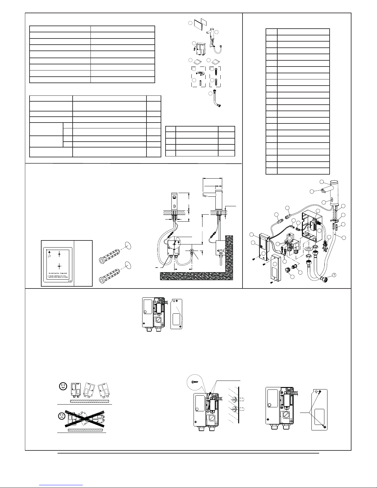
Filter plug
DIP switch
adjustment (Fig. 6.1)
(Fig. 6.2)
Filter plug
DIP switch
adjustment (Fig. 6.1)
(Fig. 6.2)
6.1 Sensing range adjustment (Fig. 6.1)
Remove rubber plug and set switch to :
Position a. Security off after 45 seconds or.
Position b. Security off after 3 seconds.
Position c. Variable Detection Range Adjustment mode.
Position d. Detection Range – Factory or Adjusted setting.
(Note: Factory default setting fixed at 150mm +/-50mm)
- To adjust the sensing distance to your personal preference, select dip switch option “Position c”.
- Disconnect the power (AC or DC)
- Hold a reflective surface (e.g. white carton) at the distance required from the sensor (Note that a highly reflective
surface, such as a white carton, will have approx. 100mm longer sensing distance than a typical hand, when
judging your preferred sensing range)
- Reconnect the power and maintain the reflective surface at the required distance.
- Observe the flashing light in the sensor which should stop after 4 flashes or approximately 5 seconds. If the light
continues to flash, the reflective surface has been positioned too close to the sensor and the new setting will not
be registered. Reposition the reflective surface 100mm farther away from the sensor and repeat the above steps.
- When the light has stopped flashing ( or the 5 seconds has elapsed), remove the reflective surface and set the
dip switch to “Position d”, within 60 seconds. NOTE: If the dip switch is not switched to “Position d” within the 60
seconds, the sensing range will automatically adjust back to the factory default setting.
- Once the new setting has registered with the controller, this will be the default setting for selected “Position d”.
- NOTE: In “Position d” the sensing range will be reset to the factory default if the power is disconnected for more
than one minute, after which your preferred setting would need to be re-establish following the above instructions.
- Replace the rubber plug and secure the assembly.
(Fig. 4.6)
(Fig. 4.7)
(Fig. 4.8)
Sensor Cable
Fixation washer
Fixation nut
Basin
(Single hole)
ø3.6cm (Max)
For marking of taps intended for
the supply of tempered water only,
consult the relevant regulatory body.
(1) Place hand under faucet, water will
flow automatically.
Sensing range will be adjusted
automatically in 3 seconds after
power up.
(2) Remove hand, water will stop
automatically within 0.5~1 sec.
(3) The LED will be on for 1 second after
detection.
Detection and still working, but LED
flashes which signals “low voltage”
(4) With the security setting to be off after
45 seconds and detection range set
dynamically, the water will stop flowing
after 1 minute. (Refer to 6.1)
LED
Water
Outlet
Water
Inlet
Supply
Hose
Angle Valve
Control Box
Sensor Connector
To
Spout
7. CLEANING INSTRUCTIONS:
- Use soft, dry or damp cloth only to clean the control box, sensor
window and faucet. Do not use any abrasive material, chemicals
and excessive water to clean the unit, as this may damage the
plated finish and the sensor.
Recommendation: If intended to be installed with tempered water, the
sensor tap must be installed with a Zip Thermostatic Mixing Valve or similar
product and in accordance with local authority guidelines.
6.2 Cleaning the Filter (Fig. 6.2)
Filter should be checked regularly.
- Remove right control box cover.
- Shut-off water supply at angle valve.
- Remove filter plug and filter, then
wash thoroughly and re-assemble.

Page 4 Sensor Tap AC operating instructions - 87337 - April 2012 v1.01
Head Office
Zip Heaters (Aust) Pty. Ltd.
ABN 46 000 578 727
67 Allingham Street
Condell Park NSW 2200
Postal: Locked Bag 80
Bankstown 1885 Australia
Website: www.zipheaters.com
Facsimile (02) 9796 3858
Telephone (02) 9796 3100
Free Call 1 800 638 633
In order to help preserve our environment we ask that you
dispose of this product correctly. Please contact your local
city council for collection centre details.
As Zip policy is one of continuous product improvement, changes to specifications may be
made without prior notice. Images in this booklet have been modified and may not be true
representations of the finished goods.
9. TROUBLE SHOOTING (FOR QUALIFIED ELECTRICIAN USE ONLY) :
(1) The LED is not on, no water flows.
Problem Solution
a. Detection range too is short Refer to 6.1 for adjustment
instructions
b. Power supply is not properly
connected Re-connect
c. No power supply Turn on the indoor power
d. Transformer connector is loose Connect it properly
e. Circuit board faulty Do not attempt to repair, contact
your dealer
f. If the supply cord is damaged
It must be replaced by the
manufacturer, the manufacturer’s
agent or a similarly qualified
person in order to avoid a hazard.
(2) The LED is on, no water flows.
Problem Solution
a. Filter is clogged Clean as per 6.2
b. Solenoid connector is loose Connect it properly
c. Solenoid valve is faulty Do not attempt repair, contact your
dealer.
Other Zip Accessories manuals