© 2014 EMS Radio Fire & Security Systems Ltd. All rights reserved 1 / 44 / 4 TSD015 ISS2f 17/02/14 AJM© 2014 EMS Radio Fire & Security Systems Ltd. All rights reserved TSD015 ISS2f 17/02/14 AJM
Approved to EN54-18
EN54-25
Application Intended for use in re detection
and re alarm systems in and
around buildings. Indoor use only.
European Union
directives 1999/5/EC (R&TTE directive):
Hereby EMS Radio Fire & Security
Systems declares that this device is
in compliance with the essential
requirements and other relevant
provisions of Directive 1999/5/EC.
2002/96/EC (WEEE directive):
Products marked with this symbol
cannot be disposed of as unsorted
municipal waste in the European
Union. For proper recycling, return
this product to your local supplier
upon purchase of equivalent new
equipment, or dispose of it at
designated collection points. For
more information see
www.recyclethis.info
Contact information
For contact information, see www.utcreandsecurity.com
Regulatory information
Manufacturer EMS Radio Fire & Security Systems
Ltd. Technology House, Sea Street,
Herne Bay, Kent, CT6 8JZ, United
Kingdom
Year of
manufacture See serial number label inside unit
Certication
Certication body 0359
CPR certicate 0359-CPR-00248
Specication
Operating
temperature -10 to +50°C
Storage
temperature -20 to +60°C
Humidity 0% to 95% non-condensing
IP rating IP54
Operating voltage 18 to 22V loop powered
Typical operating
current 40mA loop powered (1st loop)
+ 7mA per each connected loop
Max operating
current 47mA loop powered (1st loop)
+10mA per each connected loop
Operating
frequencies 868 MHz
Output transmitter
power Variable 0-14 dBm
Dimensions 270mm (W) 205mm (H) 75mm (D)
Weight 0.95kg
Radio Hub - Four Loop Installation Guide
General
The Ziton Radio Hub is available under the following part
number:
PART NO VARIANT TYPE
ZPR868 -H Ziton Radio Hub - Four Loop c/w wire aerials
The address of the unit is set using the menu
programming structure available on the Radio Hub – see
programming manual for details. The installation must
conform to BS5839:Part 1 (or applicable local codes). This
Radio Hub is suitable for indoor use only.
Loop design
The Radio Hub is powered from the loop; the unit draws a
typical current of 40mA (for loop 1) plus 7mA per each
additional connected loop. The current drawn from the
Hub should be taken into consideration when calculating
the total load of a loop. A maximum of one Radio Hub can
be connected to a loop.
Installation of the Radio Hub
Ensure that the Radio Hub is sited in accordance with the
survey and design details. The Radio Hub is required to be
connected via glands to the relative control panel (CIE).
The recommended minimum distance between metal
objects or other equipment from the aerial is 600mm. The
recommended minimum distance to any other electrical
equipment is 2 metres. The maximum distance between
the Radio Hub and the CIE is 10 metres.
To gain access into the unit, remove the four corner covers
and screws, allowing removal of the front plate. These
must be kept in a safe place for retting once installation
is complete. Housed inside the unit will be the following
part:-
1 x 868MHz Radio Hub pcb complete with aerials.
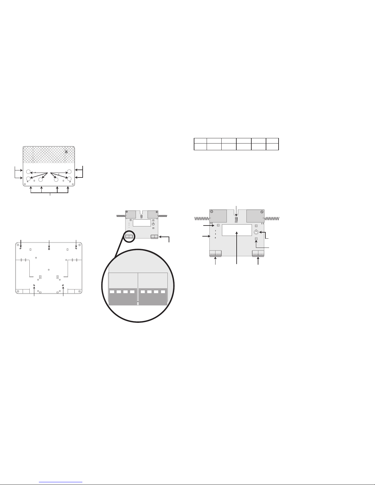
Removing the Ziton Hub PCB
Care must be taken to ensure the Ziton Hub PCB is not
damaged in the installation process. The Ziton Radio Hub
PCB can be removed for additional access to mounting
points if required. If removed, care must be taken to
ensure that the PCB is carefully stored and correctly
re-inserted and secured by the PCB retaining clips (shown
in Figure 1).
Figure 1
PCB
retaining
clips
In order to remove the PCB, rstly remove the PCBs
central retaining screw then release the top two retaining
clips, by gently easing them outwards. This will allow the
top of the board to be freed. Release the bottom two
retaining clips by gently easing them outwards. This will
release the PCB.
Having now unclipped the PCB, it must be carefully lifted
away from the casework and stored in a suitable, safe
location.