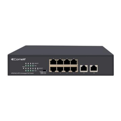
Light: There is a PoE PD connected to be port, which
supply power successfully.
Blink: Indicates port abnormal power supply.
Rear Panel
The rear panel of 4+2 100Mbps indicates AC inlet power socket, Select different power supplies corresponding to
different voltage inputs as follows:
Note: the lightning protection grounding column is located on the left side of the rear panel, please make sure to
use the conductor to ground in case of lightning!
Installation the Switch
This part describes how to install your Ethernet Switch and make connections to it. Please follow the following
instructions in avoid of incorrect installation causing device damage and security threat.
⚫Before cleaning the switch, unplug the power plug of the switch first. Do not clean the switch with wet cloth or
liquid;
⚫Do not place the switch near water or any damp area. Prevent water or moisture from entering the switch
chassis;
⚫Do not place the switch on an unstable case or desk. The switch might be damaged severely in case of a fall;
⚫Ensure proper ventilation of the equipment room and keep the ventilation vents of the switch free of
obstruction;
⚫Make sure that the operating voltage is the same one labeled on the switch;
⚫Do not open the chassis while the switch is operating or when electrical hazards are present to avoid electrical
shocks.
Wall-mounted installation
In the first two fixed screw on the wall as shown in the figure below
Aim at the two fixed hole switches, and the machine smoothly on the screw
Provide two screws with a diameter of about m3 and a nut diameter of 5mm
