2
SL3000UL AND CSW200 (STANDARD
OPERATORS):
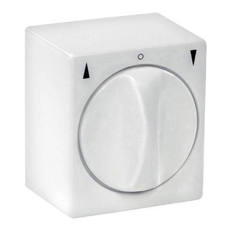
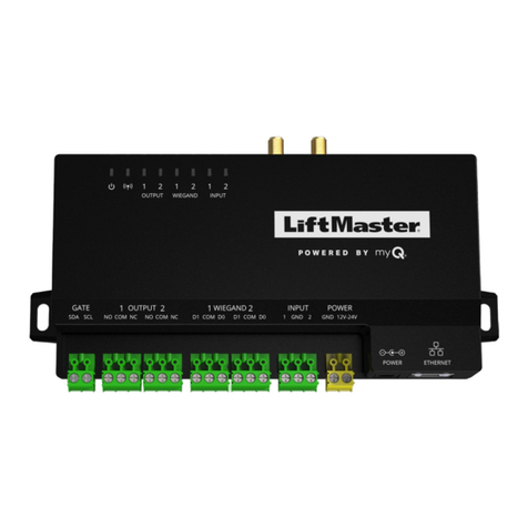
• Route the wires into the electrical box and plug the connector
on the reset switch to J5 on the Omni board (Figure 3).
OR
SL3000UL WITH EMERGENCY RELEASE
(NO BATTERY BACK-UP):
• Remove the connector from the reset switch by cutting off
connector. Strip insulation from wires. Insert wire and crimp
faston (Figure 4).
• Remove 3 screws from the emergency release (Figure 5).
• Plug the fastons from the reset switch harness onto the
piggyback fastons already connected to the interlock switch
(Figure 6).
OR
SL3000UL AND CSW200UL WITH
BATTERY BACK-UP
(WITH/WITHOUT EMERGENCY
RELEASE):
• Remove the connector from the reset switch by cutting off
connector. Strip insulation from wires (Figure 7).
• Insert the stripped terminals into DC back-up connector with
red wire to terminal #3 and black wire to #4.
6. Drill access hole in the cover of operator using the appropriate
template on the following page.
• Apply the template to the cover and align both edges of slot
and bottom of the cover, then drill a hole (Figure 8).
• Affix the reset label around the hole.
5. Connect the wires for the reset switch referring to the
instructions appropriate to the operator.
J5
FIRE
DEPT.
3
STRIKE
OPEN
RADIO
RECEIVER
TIMER
EM ON
EXIT
LOOP
REVERSE
SENSOR
OPEN
STOPCLOSE
SAFETY
LOOP
CENTER
LOOP
GATE
LOCKED
60 POWER
OVERLOAD
OFF
OPEN LEFT
DC-BACKUP
ALARMSENSOR
OPEN RIGHT
3
RS
RESET
MOTOR
13
13
COMMAND
PROCESSED
ON
MADE IN USA
Plug Reset
Switch Connector
to J5 Connector
Black Wire
to #4
Connector
VI
,
III
,
II,I
SSALC
Socket
13
2
7
6
5
4
Red Wire
to #3
FIGURE 3
FIGURE 6
FIGURE 7
5. Connect the wires for the reset switch referring to the
instructions appropriate to the operator.
SL3000UL AND CSW200 (STANDARD OPERATORS):
• Route the wires into the electrical box and plug the
connector on the reset switch to J5 on the Omni board
(Figure 3).
OR
SL3000UL WITH EMERGENCY RELEASE
(NO BATTERY BACK-UP):
• Remove the connector from the reset switch by cutting off
connector. Strip insulation from wires. Insert wire and
crimp faston (Figure 4).
• Remove 3 screws from the emergency release (Figure 5).
• Plug the fastons from the reset switch harness onto the
piggyback fastons already connected to the interlock switch
(Figure 6).
OR
SL3000UL AND CSW200UL WITH BATTERY BACK-UP
(WITH/WITHOUT EMERGENCY RELEASE):
• Remove the connector from the reset switch by cutting off
connector. Strip insulation from wires (Figure 7).
• Insert the stripped terminals into DC back-up connector
with red wire to terminal #3 and black wire to #4.
6. Drill access hole in the cover of operator using the
appropriate template on the following page.
• Apply the template to the cover and align both edges of slot
and bottom of the cover, then drill a hole (Figure 8).
• Affix the reset label around the hole.
Emergency Release
Screws
FIGURE 5
SWINGGATE
TEMPLATE
SLIDEGATE
TEMPLATE
Drill 7/8" Hole
CSW200 SL3000
FIGURE 8
Remove Connector Install Insulated Fastons
and Crimp Tightly to Wire
FIGURE 4
Emergency Release
Reset Switch Wire
Piggyback Faston
Interlock Switch


