ZIV DRA-2 User manual

Making the Smart Grid Real
1/158
ZIV
Antonio Machado,78-80
08840 Viladecans, Barcelona-Spain
Tel.: +34 933 490 700
Fax: +34 933 492 258
Mail to: ziv@zivautomation.com
www.zivautomation.com
DRA-2
UNIVERSAL COMMUNICATION NODE
USER GUIDE
Rev. 5 - January 2018

DRA-2
DRA-2 UNIVERSAL COMMUNICATION NODE 2/158
USER GUIDE - Rev.5 (January 2018)
SAFETY SYMBOLS
WARNING OR CAUTION:
This symbol denotes a hazard. Not following the indicated procedure,
operation or alike, could mean total or partial breakdown of the
equipment or even injury to the personnel handling it.
NOTE:
Information or important aspects to take into account in a procedure,
operation or alike.

DRA-2
DRA-2 UNIVERSAL COMMUNICATION NODE 3/158
USER GUIDE - Rev.5 (January 2018)
CONTENTS
Page
1INTRODUCTION 6
1.1 INTELLIGENT NETWORKS 6
1.2 DRA-2 SOLUTION 6
1.3 DRA-2 INTERFACES 9
1.4 TECHNICAL SPECIFICATIONS 12
1.4.1 Characteristics of the DRA-2 with switch functionality 12
1.4.2 Characteristics of the DRA-2 with router functionality 12
1.4.3 Equipment management 12
1.4.4 Additional services 13
1.4.5 Accessories 13
1.4.6 Certifications 13
1.4.7 Equipment interfaces 14
1.4.7.1 GPRS (2G) interface characteristics 14
1.4.7.2 UMTS (3G) interface characteristics 14
1.4.7.3 MV BPLC (high speed) interface characteristics 15
1.4.7.4 MV SSPLC (long range) interface characteristics 15
1.4.7.5 Cable modem characteristics 15
1.4.8 Mechanical characteristics 16
1.4.9 Operating conditions 17
1.5 WARNINGS 18
1.5.1 Warnings before installing 18
1.5.2 Equipment safety considerations 18
2MECHANICAL AND ELECTRICAL CHARACTERISTICS 19
3LED SIGNALLING 25

DRA-2
DRA-2 UNIVERSAL COMMUNICATION NODE 4/158
USER GUIDE - Rev.5 (January 2018)
Page
4ACCESS TO THE EQUIPMENT 30
4.1 CONSOLE 30
4.2 HTTP SERVER 31
5CONFIGURATION AND MANAGEMENT 33
5.1 GENERAL PARAMETERS 34
5.1.1 Equipment identification 35
5.1.2 Access control 35
5.1.3 Others 36
5.1.4 Syslog 36
5.2 ADMINISTRATION 37
5.3 LAN CONFIGURATION 38
5.3.1 Ports 38
5.3.2 VLAN 40
5.3.2.1 PVLAN function 41
5.3.3 PLC 43
5.4 WAN CONFIGURATION 46
5.4.1 Cell0 configuration 46
5.4.2 Tunnel configuration 57
5.4.3 CM configuration 60
5.5 QoS CONFIGURATION 61
5.5.1 QoS Layer 2 61
5.5.2 QoS Layer 3 64
5.6 ROUTING CONFIGURATION 67
5.6.1 Static routes 67
5.6.2 RIP Protocol 70
5.6.3 OSPF Protocol 72
5.7 FILTERING CONFIGURATION 76
5.8 NAT CONFIGURATION 78
5.9 DHCP RELAY CONFIGURATION 79

DRA-2
DRA-2 UNIVERSAL COMMUNICATION NODE 5/158
USER GUIDE - Rev.5 (January 2018)
Page
5.10 DHCP SERVER CONFIGURATION 79
5.10.1 DHCP Server Profiles 80
5.10.2 DHCP Server Table 81
5.11 VRRP CONFIGURATION 81
5.12 VPN CONFIGURATION 85
5.13 NHRP CONFIGURATION 90
5.14 SNMP CONFIGURATION 93
5.15 STP 95
5.16 NTP CONFIGURATION 98
5.17 ACCESS CONFIGURATION 100
5.18 SECURITY CONFIGURATION 101
5.18.1 802.1x 10²
5.18.2 MAC list 104
5.19 REBOOT 105
5.20 CODE REFLASH 105
5.20.1 Backup 105
5.21 CONFIGURATION FILE 106
5.21.1 Upload (from the PC to the equipment) 106
5.21.2 Download (from the equipment to the PC) 107
6STATISTICS 108
APPENDIX A
BIBLIOGRAPHY AND ABBREVIATIONS 117
APPENDIX B
DATA STRUCTURE IN CLI 122
APPENDIX C
WIDEBAND PLC COUPLERS 156

DRA-2
DRA-2 UNIVERSAL COMMUNICATION NODE 6/158
USER GUIDE - Rev.5 (January 2018)
1 INTRODUCTION
1.1 INTELLIGENT NETWORKS
Intelligent Electrical Grids or "smartgrids" are known to everyone, and not just
specialists/technicians from the electrical sector. Nowadays, it is usual for the press to
publish articles about breakthroughs in this field. The diverse applications of "smartgrids"
are known to all; from demand management thanks to the new smart meters, to the
automation of distribution, the integration of renewable energies and the impact of electric
vehicles in future networks, etc.
To make those applications real, different technologies are required. Those technologies
include telecommunications, which play a fundamental role.
Electricity distribution companies have been deploying telecommunication networks to
provide remote connectivity to all their electrical substations. The new "smartgrid"
applications must provide safe connectivity for Transformation Centres. This aspect poses
an enormous challenge for the telecommunications areas of many electricity distribution
companies, mainly because of the large number of installations and the virtual lack of
connectivity in those installations at the present time.
The automation of transformation centres is therefore a necessary step on the way to
implementing "SmartGrids".
1.2 DRA-2 SOLUTION
To convert the new "smartgrid" applications into a reality, Transformation Centres need
more communications. But what type of information must the new telecommunications
equipment installed by us transmit?.
ZIV is in favour of the DRA-2 universal communication equipment for Medium Voltage
Transformation Centres.

DRA-2
DRA-2 UNIVERSAL COMMUNICATION NODE 7/158
USER GUIDE - Rev.5 (January 2018)
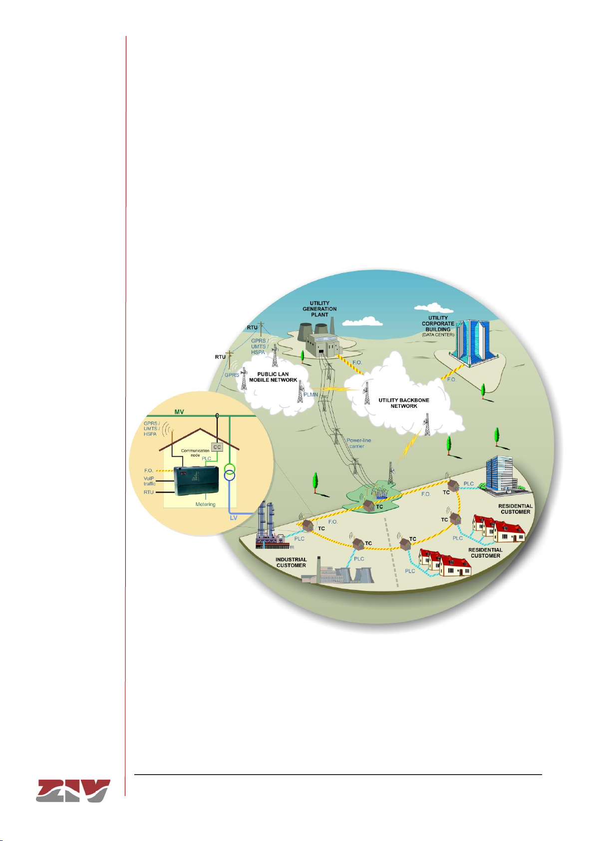
The DRA-2 equipment is designed to transmit the services in a Transformation Centre to
higher levels in the electrical grid, through a wide range of interfaces:
Optical fibre
Medium Voltage Powerline Communications Technology (BPLC and SSPLC interfaces)
Cell technologies (GPRS/UMTS)
ADSL lines
Cable modem
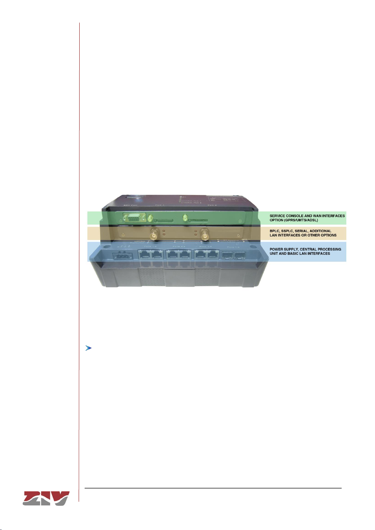
The DRA-2 includes, as standard features, a serial maintenance interface, 6 Fast Ethernet
ports and 2 Gigabit Ethernet SFP bays.
The Fast Ethernet ports are usually used to provide service to the equipment in the
Transformation Centre (TC), such as PLC meter reading concentrators, remote telecontrol
units, protections, fault circuit indicators, cameras or IP phones.
The 2 Gigabit Ethernet SFP bays permit the inclusion of the DRA-2 communication node in
Optical Fibre ring-type topologies, or its use as a high-capacity uplink.
Clients should complete the equipment by selecting the different available interface options
(see section 1.3).
In addition to the switch function (L2), the DRA-2 has IPv4 route capacity (L3), which permits
various operation scenarios:
Option of operating as a switch for Ethernet, Gigabit Ethernet and PLC-MV (BPLC)
interfaces.
Routing functionality between two or more configured VLANs, with each VLAN being
made up of a set of local ports (Ethernet / Gigabit Ethernet / BPLC) and WAN interfaces
(GPRS / UMTS / ADSL).
The use of wireless WAN interfaces (GPRS / UMTS) as safety recourse (backup) for the
routing functionality described in the preceding section.
For the routing functions, the equipment supports the use of static (configured by the users)
and dynamic routing information, for which it has the standard RIP and OSPF routing
protocols.

DRA-2
DRA-2 UNIVERSAL COMMUNICATION NODE 8/158
USER GUIDE - Rev.5 (January 2018)
The DRA-2 can be managed locally and remotely, through a console or through a built-in
web server, http or https, SSH connection and Telnet.
The DRA-2 also supports the SNMPv1, SNMPv2c and SNMP3 protocols, as well as other
protocols and services such as DHCP, NTP, TACACS+ and RADIUS.
The DR-2 stores internally an application software backup so that, in case of failure,
equipment operation by running the backup software is guaranteed.
FIGURE 1 DRA-2 solution

DRA-2
DRA-2 UNIVERSAL COMMUNICATION NODE 9/158
USER GUIDE - Rev.5 (January 2018)
1.3 DRA-2 INTERFACES
One noteworthy aspect of the DRA-2 is its large variety of interfaces, which enables it to
provide a solution to the different topologies present in Transformation Centres. In some
Transformation Centres, PLC-MV technology is the only valid option, whereas in others
optical fibre or even ADSL (PSTN) can be used. Moreover, in cases where none of the
above options can provide sufficient communication, wireless interfaces or cable modem
(HFC modem) can be used.
FIGURE 2 Constitution of the DRA-2 node
The different basic and optional interfaces are integrated into the following three principal
modules (see FIGURE 2):
POWER SUPPLY, CENTRAL PROCESSING UNIT AND BASIC LAN INTERFACES.
This is the basic DRA-2 module. As the Central Processing Unit and element that
adapts and controls the peripherals, it carries out advanced Ethernet switching
functions (L2), routing functions, access protocols, flows and congestion controls and
advanced traffic management functions.
It has 6 Fast Ethernet ports in a 10/100Base-Tx configuration.
It has also 2 receptacles for Gigabit Ethernet SFP transceivers.
The power supply is included in the basic module and there are two versions: the first
for use with continuous current of 48 VDC, while the second admits the use of
alternating current and continuous current, but in this case, from a voltage range of
over 80 VDC. Both versions generate the internal supply voltages based on the input
voltage, and have several input filters for protective purposes. The power supply is
protected against reverse polarity.

DRA-2
DRA-2 UNIVERSAL COMMUNICATION NODE 10/158
USER GUIDE - Rev.5 (January 2018)
SERVICE CONSOLE AND WAN INTERFACES OPTION (GPRS/UMTS/ADSL)
This module has a connector known as SRV for accessing the equipment through the
console. That connector is always included as a basic element.
It may also have WAN interfaces, and users must select one of the following options:
- 1 GPRS (2G) with 1 SIM and 1 SMA antenna connector
- 1 GPRS (2G) with 2 SIMs and 1 SMA antenna connector
- 2 GPRS (2G) with 2 SIMs and 2 SMA antenna connectors
- 1 GPRS (2G) with 1 SIM and 1 SMA antenna connector + 1 ADSL (on request)
- 1 ADSL (on request)
- 1 GPRS (2G) with 1 SIM and 1 SMA antenna connector + 1 UMTS with 1 SIM and 1
SMA antenna connector (on request)
- 1 UMTS (3G) with 1 SIM and 1 SMA antenna connector + 1 ADSL (on request)
- 1 UMTS (3G) with 1 SIM and 1 SMA antenna connector
- 1 UMTS (3G) with 2 SIMs and 1 SMA antenna connector
PLC-MV, ADDITIONAL LAN INTERFACES OR OTHER OPTIONS
This module may be prepared for different types of interface. Users should select one
of the following options:
- 1 high speed BPLC interface
- 2 high speed BPLC interfaces
- 1 low speed SSPLC interface (in the process of being developed)
- 2 low speed SSPLC interfaces (in the process of being developed)
- 1 cable modem (non-compatible with PLC option)
- 2 additional Fast Ethernet interfaces (100Base-Tx or 100Base-Fx) (in the process of
being developed)
- 1 RS-232 serial interface (in the process of being developed) (not valid with 1 ADSL
or 2 PLCs)
- 1 RS-485 serial interface (in the process of being developed) (not valid with 1 ADSL
or 2 PLCs)
- 1 optical serial interface (in the process of being developed) (not valid with 1 ADSL
or 2 PLCs)
- 1 PLC meter reading concentrator (in the process of being developed)

DRA-2
DRA-2 UNIVERSAL COMMUNICATION NODE 11/158
USER GUIDE - Rev.5 (January 2018)
WAN interfaces allow users to utilise the services of public operators and are a very useful
alternative, in view of their geographical coverage and the fact that they are easy to put into
operation.
The cable modem is the necessary device to access the services of the cable operators.
The MV PLC is a good option for transmitting information from the different Transformation
Centres to a Main Substation. There are two types of interface for Powerline
Communications through the Medium voltage network:
A high speed BPLC interface, designed especially for urban environments in which mid-
distance levels must be covered, since the transformation centres are very close to each
other.
A low speed SSPLC interface which allows much greater distances to be covered,
designed for rural environments where the quantity of information to be transmitted is
much smaller and priority is given to covering longer distances and accessing more
remote areas.
For injecting the PLC signal in the Medium Voltage networks, Wideband PLC couplers are
used, adapted to that technology, and to the different installation sites. The available range
is described in APPENDIX C.

DRA-2
DRA-2 UNIVERSAL COMMUNICATION NODE 12/158
USER GUIDE - Rev.5 (January 2018)
1.4 TECHNICAL SPECIFICATIONS
1.4.1 Characteristics of the DRA-2 with switch functionality
➢Port speed automatic detection.
➢STP and RSTP for resolving loops in the network and operation in rings.
➢VLANs management per port.
➢QoS management per VLAN (802.1p).
➢Broadcast and Multicast (Broadcast Storm Control) traffic limitation.
➢MAC access control lists and 802.1x user authentication.
➢Level 2 switching between Ethernet and PLC-MV environment in the event of having a
Medium Voltage BPLC interface.
1.4.2 Characteristics of the DRA-2 with router functionality
➢Routing, filtering, NAT, firewall and tunneling capabilities.
•Up to 6 simultaneous IPSec tunnels with DMVPN (Dynamic Multipoint VPN) and
NHRP (Next Hop Resolution Protocol) support.
•RIP and OSPF routing protocols.
•VRRP redundancy protocol.
➢Assignment of Quality of Service, and layer 3/4 Quality of Service management. Priority
management levels are the following:
•Quality per origin and/or destination IP address.
•Quality per type of traffic (DSCP or TOS) and service (protocol and port).
➢Models having 2 wireless interfaces support the establishment of two IP links
simultaneously, both performing as active backup, with fast switching, or load balance.
1.4.3 Equipment management
➢Local and remote access through a console or through a built-in web server, http or
https, SSH connection and Telnet.
➢The wireless interface model allows for manage through data calls.

DRA-2
DRA-2 UNIVERSAL COMMUNICATION NODE 13/158
USER GUIDE - Rev.5 (January 2018)
1.4.4 Additional services
➢SNMP agent
➢DHCP server and client
➢NTP server and client
➢TACACS+ client
➢RADIUS client
➢DHCP Relay
➢PVLAN (RFC 5517)
1.4.5 Accessories
➢SFP modules.
➢Antenna cables.
➢Antennas.
➢Ethernet Cables.
➢Optical fibre pigtails.
➢PLC coaxials.
➢Wideband PLC couplers (see Appendix C).
1.4.6 Certifications
➢CE.
➢Designed for industrial applications.
➢Designed for Electrical Substations.

DRA-2
DRA-2 UNIVERSAL COMMUNICATION NODE 14/158
USER GUIDE - Rev.5 (January 2018)
1.4.7 Equipment interfaces
➢Basic interfaces:
•6 Fast Ethernet ports in 10/100Base-Tx configuration.
•2 Gigabit Ethernet SFP ports.
•1 service console.
➢The interfaces provided by the available options
*
:
•GPRS (2G) / UMTS (3G) and ADSL (on request)
•BPLC
•SSPLC (being developed)
•cable modem (DOCSIS/EuroDOCSIS 1.0/1.1/2.0)
•Fast Ethernet (100Base-Tx or 100Base-Fx) (being developed)
•RS-232, RS-485, optical serie (being developed)
1.4.7.1 GPRS (2G) interface characteristics
➢Quad band: 850/900/1800/1900MHz.
•Class 4 (+33dBm ±2dB) for EGSM850
•Class 4 (+33dBm ±2dB) for EGSM900
•Class 1 (+30dBm ±2dB) for GSM1800
•Class 1 (+30dBm ±2dB) for GSM1900
1.4.7.2 UMTS (3G) interface characteristics
➢UMTS/HSDPA: Dual band, 900/2100MHz
➢GSM/GPRS/EDGE: Dual band, 900/1800MHz
•Class 4 (+33dBm ±2dB) for EGSM900
•Class 1 (+30dBm ±2dB) for GSM1800
•Class E2 (+27dBm ± 3dB) for GSM 900 8-PSK
•Class E2 (+26dBm +3 /-4dB) for GSM 1800 8-PSK
•Class 3 (+24dBm +1/-3dB) for UMTS 2100, WCDMA FDD BdI
•Class 3 (+24dBm +1/-3dB) for UMTS 900,WCDMA FDD BdVIII
*
See list of combinations permitted in section 1.3, DRA-2 interfaces.

DRA-2
DRA-2 UNIVERSAL COMMUNICATION NODE 15/158
USER GUIDE - Rev.5 (January 2018)
1.4.7.3 MV BPLC (high speed) interface characteristics
➢Frequency range of 2 to 30 MHz.
➢200 Mbit/s
*
channel rate.
➢150 Mbit/s*user max. rate.
➢AES encryption of 128 bits.
➢Flexibility in suppressing certain frequencies to prevent interference with other services.
➢OFDM modulation with 1155 useful carriers.
➢1024/256/64/16/8 QAM, QPSK, BPSK, ROBO modulation (DBPSK basic/robust
modulation) –independently applied to each carrier.
➢Output power of between 1 and 10 W
➢Range of up to 1 km*.
1.4.7.4 MV SSPLC (long range) interface characteristics
➢Frequency range of 2 to 10 MHz.
➢128 kbit/s
†
speed.
➢Direct-Sequence Spread Spectrum (DSSS) Modulation.
➢Output power of between 1 and 10 W
➢Distances up to 5 km*.
1.4.7.5 Cable modem characteristics
➢Protocol support:
•DOCSIS/EuroDOCSIS 1.0/1.1/2.0
•SNMP v1, v2c, v3
➢Connector: F-type female 75 ΩRF
➢Receiver
•Demodulation: 64/256 QAM
•Maximum speed: 38 Mbit/s (64 QAM) / 43 Mbit/s (256 QAM) DOCSIS
•Frequency range: 108 ÷ 860 MHz (EuroDOCSIS)
•Signal level: -13 ÷ 17 dBmV (EuroDOCSIS)
•Input return loss: >6 dB EuroDOCSIS (108 ÷ 860 MHz)
*
There is a trade-off between transmission rate, distance and SNR needed in the receiver.
†
There is a trade-off between transmission rate, distance and SNR needed in the receiver.

DRA-2
DRA-2 UNIVERSAL COMMUNICATION NODE 16/158
USER GUIDE - Rev.5 (January 2018)
➢Transmitter
•Modulation:
TDMA: QPSK, 8QAM, 16QAM, 32QAM, 64QAM
S-CDMA: QPSK, 8QAM, 16QAM, 32QAM, 64QAM,128QAM
•Maximum speed:
320, 640, 1280, 2560, 5120 kbit/s (QPSK)
640, 1280, 2560, 5120, 10240 kbit/s (16QAM)
•Frequency range: 5 ÷ 65 MHz (EuroDOCSIS)
•Bandwidth:
TDMA: 200, 400, 800, 1600, 3200 and 6400 kHz
S-CDMA: 1600, 3200 and 6400 kHz
•Signal level:
TDMA: +8 ÷ +54 dBmv (32QAM, 64QAM)
+8 ÷ +55 dBmv (8QAM, 16QAM)
+8 ÷ +58 dBmv (QPSK)
S-CDMA: +8 ÷ +53 dBmv (all modulations)
•Output level of CM can be automatically controlled by CMTS through power ranging
(1dB steps)
•Output return loss: >6 dB EuroDOCSIS (5 ÷ 65 MHz)
➢CPEs
•Maximum number of CPEs: 32 (32 MAC addresses)
•Filtering:
LLC: 16
IP: 32
•Frequency searching
Frequency cache: 4 entries
Channel plan: 8 MHz, 1 MHz, 0.25 MHz (EuroDOCSIS)
➢SIDS
•Number of SIDs: 16
➢Management
•MIBs: MIB II, MCNS MIB
1.4.8 Mechanical characteristics
➢Dimensions Height: 140 mm; Width: 220 mm; Depth: 94 mm.
For more mechanical and electrical details about the connectors see chapter 2,
Mechanical and electrical characteristics.
➢Weight 1 Kg.
➢DIN rail installation (EN 50022, BS 5584, DIN 46277-3)
➢IP protection level: IP 2xB
➢Material: Grey (RAL 7024) Lexan 920 fire-resistant (UL 94 V0) plastic

DRA-2
DRA-2 UNIVERSAL COMMUNICATION NODE 17/158
USER GUIDE - Rev.5 (January 2018)
1.4.9 Operating conditions
➢Power supply: 16-75 Vdc (48 Vdc nominal) or multirange (80-360 Vdc, 80-260 Vac).
➢Temperature and humidity: from -20ºC to +70ºC and relative humidity not greater than
95%, in accordance with IEC 721-3-3 class 3K5 (climatogram 3K5).
➢Power consumption: Max. 15 W.
➢Electrical safety: In accordance with EN 60950 standard.
➢R.F. emissions: In accordance with EN 55022 standard.
➢Immunity to electrostatics discharges: In accordance with UNE-EN 61000-4-2 standard.
➢Immunity to R.F. permanent electromagnetic fields: In accordance with UNE-EN 61000-
4-3 standard.

DRA-2
DRA-2 UNIVERSAL COMMUNICATION NODE 18/158
USER GUIDE - Rev.5 (January 2018)
1.5 WARNINGS
1.5.1 Warnings before installing
1. The installation of the DRA-2 in Electrical Substations or Secondary
Substations is generically subject to the fulfilment of all the safety measures
and prevention of risks established for this type of work by the electricity
company that will use these devices and the Safety standards (EN 50110).
2. In order to install and handle the DRA-2 the following points must be
complied with:
- Only qualified personnel appointed by the electricity company that owns
the installation should carry out the installation and handling of the DRA-2.
- The environment in which it is to operate should be suitable for the DRA-2,
fulfilling all the conditions indicated in section 1.4.9.
3. ZIV will not accept responsibility for any injury to persons, installations or third
parties, caused by the non-fulfilment of points 1 and 2.
1.5.2 Equipment safety considerations
1. The terminal contains components sensitive to static electricity, the following
must be observed when handling it:
- Personnel appointed to carry out the installation and maintenance of the
DRA-2 must be free of static electricity. An anti-static wristband and/or
heel connected to earth should be worn.
- The room housing the DRA-2 must be free of elements that can generate
static electricity. If the floor of the room is covered with a carpet, make sure
that it is anti-static.
2. ZIV will not accept responsibility for any damage to the equipment caused by
the non-fulfilment of point 1.

DRA-2
DRA-2 UNIVERSAL COMMUNICATION NODE 19/158
USER GUIDE - Rev.5 (January 2018)
2 MECHANICAL AND ELECTRICAL CHARACTERISTICS
The diverse elements comprising the DRA-2 communication node are supplied in a
high-resistance, epoxy plastic box, ready for DIN rail mounting.
The general dimensions of the equipment in mm are shown in FIGURE 3. The element for
fastening the equipment to the DIN rail is at the bottom of the box (see FIGURE 4).
FIGURE 3 General dimensions in mm of the DRA-2 equipment
Table of contents
Other ZIV Network Router manuals