Zlin Aircraft Z 142 Technical specifications

M an ufa ct u rer
OF THE
z 142 AIRCRAFT
ZLIN AIRCRAFT a.s.
765 81 Otrokovice
CZECH REPUBLIC
0/r23
YR:ZC- F
cf erpticn s unrJe r the ,'A"
Production No./Series
ldentification Sign
)r-rnihi f i^n ^+| anC rr U" cate qcrie s
Category *ER9BA+IHAI )
ry+f ae:.4) I'ro:ZJC7-C2CC-r
NORMAL (N)'
Certification Bases FAR PART 23 with incorporated changes up to No. 23_13
czech copy is approved by the srATE AVTATT'N TNS'ECTTON - praque No. 5326/1254t7g/Hi.
Limitations given in Section 2 and 7 must be observed during operation.
Year of lssue fv
'pt" .h\q K:^u /l
/--B\..!,1/ r)/
(/ ' 'ltt\
EEJFE .r o' \
*** ';i!*:,'#;**
DtC. cz27eg41u
1 I iil 201t1
H
1989
0- 1

a
a

a
o

a
o

CONTENTS
SECTION 1.
SECTION 2.
sEcTtoN 3.
SECTION 4.
sEcTtoN 5.
SECTION 6.
sEcTtoN 7.
General
Operaling Limitations
Emergency Procedures
Normal Procedures
Performances
Weighl and C/c Positions
Supplemenls
3- 1
5- 1
6- 1
7-'l

o
o

SECTION 1
1. GENERAL
CONTENTS
htroduction
Changes
Abbrevialions and Definitions
Dimensional sketch of the z 142 Aircraft
Specification
Principal Technical Data
Pilot's Cockpit
Page
t-J
t-J
1-5
1-6
1- 10
1- 13

io
o

L
1.1.
SECTION 1
GENERAL
INTRODUCTION
Validitv:
This FLIGHT MANUAL applies onty to the aircraft, whose production number is introduced on
the page 0-1.
Caution:
The aircran pilot must be acquainted with the contents of this FLIGHT MANUAL before the
flight.
1.2. CHANGES
1,2.1, All changes or supplements of this Flight Manual are performed as follows:
1) The aircraft manufacturer will send the binding bulletin with changes or new correcteo pages
of the Flighl Manual to the holder of the Flight Manual.
2) The holder of the Flight Manual is under an obligation
a) of recording the obtained change into the LIST OF CHANGES - item 1.2.2.
b) of carrying out of the change in accordance with the bulletin or of replacing the original
pages by new corrected ones marked with date of issue and with abbreviation .REV..
Note:
The changes or supplemented perts of the text will be marked with vertical line.
t-J

-
SECTION 1
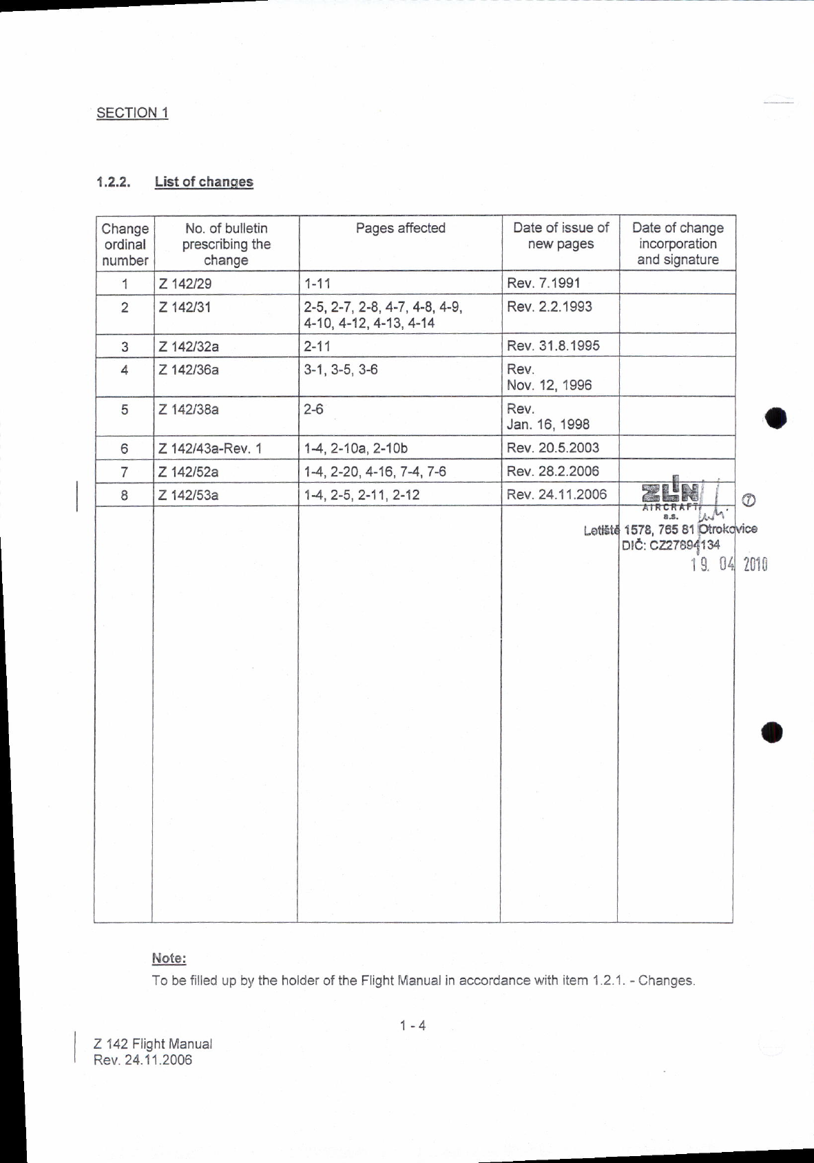
1,2,2, List ot chanqes
Note:
To be filled up by the holder of the Flight l\.4anual in accordance with item 1 .2.1 . - C\anges.
1_4
Z 142 Flight Manual
Rev. 24.11.2006
70iCI
Change
ordinal
number
No. of bulletin
prescribing the
cnange
Pages affected Date of issue of
new pages Date of change
incorporation
and signature
1z 142t29 1-11 Rev. 7.1991
az 142t31 2-5,2-7,2-8, 4-7, 4-8, 4-9,
4-10, 4-12, 4-13, 4-14 Rev.2.2.1993
Z 142132a Rev.31.8.1995
Z 142136a 3-1,3-5,3-6 Rev.
Nov. 12, 1996
5Z 142138a z-o Rev.
Jan. 16, 1998
oZ 142143a-Rev. I14, 2-10a,2-10b Rev.20.5.2003
7Z 142152a 14, 2-20, 4-16,74,7-6 Rev.28.2.2006
6Z 142153a 14,2-5,2-11,2-12 Rev. 24.1 1 .2006 KUe
Loti6ti ^'^;:'.^ 1{\'
1578, 765 81 Ptrok(
olC: cz27esd134
1 g. i4

sEcTtoN 1
1.3. ABBREVTATIONSANDDEFINITTONS
ISA
MAC
Vrue
Vso
calibrated airspeed meens indiceted airspeed of an aircraft, corrected for position
and instrument error. Calibrated airspeed is equal to true airspeed in standard
atmosphere at sea level.
Equivarent sircpeed means the caribrated airspeed of an aircrafl corrected for
adiabatic compressibre frow effect for the particular artitude. Equivarent airspeed is
equal lo calibrated airspeed in standard atmosphere al sea level.
Indiceted.airspeed means the speed of an aircraft as shown on its pitot static
airspeed indicator calibrated to reflect standard atmosphere ediabatic
cornpressible flow effect at sea ievel unconected for airspeed syslem erors.
True airspeed means the airspeed of an aircraft rerative to undistributed air. True
airspeed is equal lo equivalent airspeed multiplied by
(qo /q ) 1/2.
I o = specific weight of air at sea level
Q = specific weight of air at specified altitude.
I nternational standard atmosphere.
Mean aerodynamic chord.
Design maneuvering speed.
Maximum flaps extended speed.
Max. never-exceed sDeed.
Max. normal operating limit speeo.
Stalling speed in the landing conliguralion.
Stalling speed or minimum steady flight speed obtained in a specified
configuration..
EAS -
TAS -

SECTION 1
1.4. DIMENSIONAL SKETCH OF Z '42 AIRCRAFT

SECTION 1
1.5. SPECTFTCAT|ON
'1.5.1. ceneral
1.5.2. The fuselaqe
1.5.3. The wino
(a) rhe z 142 aircraft rs intended for an elementary and advanced piro|s training and for
training and execution of aerobatic maneuvers, for lraining of night and instrumenl flight
and for execulion of sailplanes tow.
(b) The z 142 aircraft is a version or the z 42 M aircrafi. rt is a two-seater, singre-engined,
low wing, cantilever monoptane, equipped with a six-cylinder in-tine invert;d M 3-37 AK
engine, with a hydraulic-pitch V 500 A propeller.
is of a mixed slructure. The central supporting part is a lattice-work. lt is welded of steel tubes
and is covered by a fibre-glass body. The aft part is a semimonocoque. The construction of
pilot-s seats enables the use of back{ype parachutes. The pilot's seals in side_by-side
arrangement are adjustable into 4 posiiions. The main pilot's seat is the lefl one. Behind the
seats, the hand-luggage platform is situated. The canopy can be opened by sliding forward and
is equipped with device for emergency release. For locking the canopy in par y opened
position. the delent serves.
is of all-metal structure with main and auxiliary spar. The structure of the wrng is divided at the
fuselage. The plan is of a rectangular form and the skin is of duralumin aluminium-clad sheets.
Slotted, all-metal ailerons and the flaos are eoual in size.
1 .5./1. The emDennaoe
is of a cantilever all-metal struclure, covered with duralumin sheet. Both the rudder and tne
elevator are partially mass- and aerodynamically belanced. The elevator has a balance tao ano
a controllable trim tab. The rudder has a fixed trim tab.
Caution:
1 . The control lever of the rudder balance tab has two holes.
2. There are two alternatives of attaching the pull rod to the elevator balance tab.

SECTION 1
3. With the change of pull rod attachment, it is necessary to adapt its length according to
Technical Manual of the Z '142 aircraft. item 4.3.
1.5.5. Control Svstem
The aircratt is provided with a dual control. The control system includes elevator and aileron
control, rudder control, nose wheel control, wing flaps control, trim tabs control, engine and
propeller control. The hand conlrol is of lever type, the rudder control is of a pedal type and is
equipped with a main wheel brake actuation. Elevator and ailerons are rod controlled, rudder is
rod nad cable controlled. The nose wheel conlrol is coupled with the rudder control. Wing flaps
and tim tabs are mechanically controlled.
The engine is actuated by a throttle pull rod, a mixture handle and a compressor rod. The
propeller rotation is operated by a push-pull rod.
1.5.6. Landino oear
has three wheels and consists of the main landing gear and the nose gear. The main gear
includes flat steel springs attached to the spar of the centre-section of the wing. The main gear
wheels are equipped with hydraulic disk brakes with automatic backlash elimination. The
braking plates which are located on the foot control pedals actuale the brakes of the main gear
separately. The parking brake actuates simultaneously both main wheel brakes. The nose gear
is provided with a hydropneumatic shock adsorber and with a shimmy damper, The nose wheel
is steerable through use of rudder pedals.
Pull rod altachment Balance tab travel Effect Aplication
Smaller forces in control
lever fTom elevator Recommended for
aerobatics
20" r 2"
Greater forces in control
lever from elevator Recommended for
training flights
1.8

SECTION 1
1.5.7. Power Plant
The aircrafl is powered by a piston{ype, four_stroke, aircooled, inverted in_line siw cylinoer,
left-hand engine with valve gear and camshafl on the cylinder heads, with a to*-pr#sure fuet
injection into the space in fronl of the suction valves. The engine has no reduction gear unit. ll
includes a charging compressor and is capable of aerobatics and inverted flight.
The V 500 A propeller is a two-bladed hydraulic automatic-pitch constant speed unit. propeler
blades are made of duralumin.
1.5.8. Fuel and Oit Svstem
(1) Fuet Svstem
The main fuel tanks are situated in the front parl of the wings near the fuselage (2x60 l).
The auxiliary fuel tanks are attached to the wing tips (2x5Ol).
Aerobatic fuel tank is located in the aircraft fuselage (5 l).
(2) Oil Svstem
The oil tank is located in the engine compartment in front of lhe firewall.
(3) The fuel and oil systems enable to execute aerobatic maneuvers and inverted flights (in
AEROBATTC and UTlLtTy categories onty).
1.5.9. Eouiornent
(1) Electrical Svstem is of a single-conductor type (+pole)
The earthing conductor (-pole) is formed by the aircraft frame. Rated network voltage rs
28 v. The main power source is represenred by a 600 w dynamo, driven direcfly by tne
engine. The auxiriary energy source is represented by a 25Ah battery. For the use ot an
exernat source, there is a sockel located on the left side of the fuselaoe.
(2) Extinouishino Eouioment consists of:
(a) fire-wall, separatjng the engine compartment from the airframe,
(b)
(c) engine fire edinguisher actuated from the cockpit,
cockpit fire e\tinguisher, located in the cockpit (according to customer.s oDtion).
(3) Heatino and Ventilatino Svstem
The aircraft is equipped with a regulable heating and ventiteting system of the cockoit.

SECTION 1
Liohtino
The aircraft is equipped with the following lights for the nighl flights:
- taxi and landing lights,
- position lights,
- instrument panel and cockpit ligts,
- light for reading the chart,
- anti-collision beacon.
Radiocommunication and Radionavioalion Eouioment
On customer's wish the aircran can be equipped with a:
(a) Radio of an approved type.
(b) radionavigation equipment of an approved type,
Tow Gear
A tow gear for sailplane towing can be fitled on the aircraft on customer's wish. The tow
gear consists of a ceble mount, rear-view mirror and control of the cable disengaging
device. The control rod ofthe disengaging device is situated on the panel between the
seats. Maximum take-off weight of the sailplane may be 500 kg.
lnslruments
Following instruments for the supervision of the flight, engine and airframe including
signalizalion are mounted in the cockpit.
1.6. PRINCIPAL TECHNICAL DATA
1 .6.1. Dimensions
Wing span
Length
Height
Wing: - depth (constant)
- dihedral
- sweep-foMard
- length MAC
- area
- rraver up
- travel down
- arca 2xO,7O4 m2
Ailerons:
(4)
(s)
(6)
(7)
9,160 m
7,330 m
2,7 50 m
I ,42O m
60
4' 20'
1 ,460 m^
'| 3,15 m'
21' t 1"
ta ! |
1,408 m2
1 - 10

SECTION 1
1,6.3, Weiqht and C/G Positions
Empty weight
Center of gravity position
Flighl manual Z 142
Rev. 7.1991
14" r 1"
37o r 1o
1 ,408 m'?
34" :;.
31" r 1"
1 ,23O m2
1 ,360 ml
2,590 m'
JV 1:a
JV 1Z
0,540 ml
0,810 mr
1 ,350 m2
2,330 m
1 ,660 m
420 x 150 mm
350 x 135 mm
190 kPa (1,9 kp/cm2)
250 kPa (2,5 kp/cm')
Wing flaps: - positions: RETMCTED
SIAl<I
LANDING
- area 2x0,7 04 m2
Horizontal Tail Surface (HTS):
- elevator lravel:
- stabilizer area
- elevator area
- total area HTS
Vertical Tail Surface Ml-S):
- rudder travel:
- fin area
- ructder area
- total area ws
Landing Gear: wheel track
wheel base
wheel size - main landing gear
- nose wheel
lire pressure - main landing gear
nose wheel
up
down
right
left
730 kg i 3ol"
1s % sAr.1*
Note:
Weight and C/G positions agree for all categories (A,
1.6.2. Loadinos
Category
Loading
Specific wing loading Specific power loading
(N/m2) (kg/m2) (N/kw) (ks/kW) (N/k) (ks/k)
Aerobatic (A) 7308 61 ,8 45,3 4,6
Utility (u) 761 64,9 o,o 47 ,7 4,9
Normal (N) 813 82,9 69,4 7,1 50,9 t,z
1-11

-
SECTION 1
1.6.4. Power Plant
The M 337 AK aircraft enoine
Bore
Stroke
Cylinder capacity
Compression ratio
Sense of rotation
The V 500 A orooeller
Number of blades:
Diameier:
105 mm
115 mm
5,97 litres
0,3:1
enticlockwise
Note:
(1) Maximum recommendation cruising power in high = 0 m lSA, with compressor SHUT.
(2) Maximum cruising power in high = 1200 m lSA.
(3) Short-time operaling powerwith compressor SHUT, time limiied to max. 5 min.
2000 mm
Power - RPM - Manifold Pressure
Power setting Power RPM Manifold pressure Note
KW HP kPa al
Maximum
take-off 154 ! 2% 210 t 2,5yo 2750 130 118.1 1,2*o,ot
-0.02
Maximum
c0ntnu0us 125 ! 2o/o 170 ! 2,5Yo 2600 I 3% 98 l2 1,0 1 0,02
Maximum
crursrng 103 ! ZYo 140 ! 2,5 0/o 2400 ! 3o/o 90r2 0,92 r 0,02 (1)
Maximum
cruising 100 max. '150 max. 2400 ! 3o/o 90 12 0,92 t 0,02 (2)
Short{ime
operating 132 t 2o/o 180 ! 2,5o/. 2750 ! 30 100+2 1 ,02 ! 0,02 (3)
1-12

1.7. PILOT'S COCKPIT
/a6\a
\ rl',/ \ tjt ,/ \6/
\-./ \,--z v
.il /;\ /c\
\|r'./ \a/ \l!',/
/\ ,z\ ,--<\
(9 GJ GJ
@ilErA
\s7
6\
/\
\:/
/i /a
\:/ \:/
/;q A
\9J \:/
/AA
\9d \%J
''.e
\l
J

SECTION 1
46.
+ 47.
+ 48.
+ 49.
+ 50.
1.7.1. Pilot's cockpit - leqend
1. Control stick
2. Transmitter pushbutton Cr'HF)
3. Intercom pushbutton (lC)
4. Braking plates on foot control pedals
5. Parking brake
6. Wing flaps lever
/. tnm
8. Directional irim
+ 9. Control rod of tow rope
10. Canopy emergency release handle
11. Canopy aneslment
12. Engine fire extinguisher control rod
13. Hand pump
14. Fuel priming
15. Throttle control lever
16. Propeller pitch control
17. Compressor control
18. Mixture control
19. Fuel shutoff valve
20. Venlilating and heating control
21 , Magneto switch
22. Master switch
23. Starter pushbutton
24. Sectionalizing switches
25. Control of instrument lighting intensity
26. Generator function check
27. Signalling of fuel remainder L - R
28. Signalling of Pitot system heating and ram pressure sensing unit
29. Pushbutton of signalling check (stall waming and heating)
30. Fuses
31. Earphone socket
32. Seat
33. Seat adjustment
+ 34. Board extinguisher
35. Magnetic compass L
+ 36. Magnetic compass ll.
37. Airspeed indicalor
38. Gyro horizon
39. Rate-of-climbindicator
40. Clock
41. Altimeter l.
42. Directional gyro
43. Tachomeler l.
44. Three-pointerindicator
45. Cylinder head temperature gauge
Manifold pressure gauge l.
Radio (VHF)
Airspeed indicator ll.
Turn indicator
Rate-of-ciimb indicator ll.
I 4t
Table of contents
Other Zlin Aircraft Aircraft manuals
Popular Aircraft manuals by other brands

Magni Gyro
Magni Gyro M-24C Orion Flight manual

Pelegrin
Pelegrin Tarragon Pilot's operating handbook and flight manual

broda
broda 100-PM' 100-PL operating manual

Gin Gliders
Gin Gliders Safari Passenger owner's manual

BOMBARDIER
BOMBARDIER SD3-60 Maintenance manual

Flex innovations
Flex innovations RV-8 instruction manual