Zline Attainable Luxury Alpine Series Assembly instructions

Alpine SerieS rAnge HoodS
Installation Guide
and Users Manual

ZLINE Kitchen and Bath provides Attainable Luxury, where the kitchen and bath of your
dreams is never out of reach. Through our unique designs and unparalleled quality, we’re
dedicated to providing you an elevated experience in the heart of your home. With an
endless selection of features and finishes, our inspiration is your reality.
ZLINE is fueled by a passion for innovation; A relentless pursuit of bringing the highest end
luxury designs and professional features into everyone’s homes. Because we continually strive
to improve our products, we may change specifications and designs without prior notice.
REGISTERING YOUR PRODUCT
Please register your ZLINE appliance to activate your warranty.
Begin the simple registration process by scanning the QR code.
By registering your appliance, you will have access to:
• Technical Support
• Warranty Service
• Tracking your support inquiries
WARNING: This product can expose you to chemicals including nickel, which is known to the
State of California to cause cancer. For more information, go to www.P65Warnings.ca.gov.
SCAN ME

WARRANTY
WARRANTY
PROPER VENTING REGULATIONS
Please verify with your local, city, and state regulations on the proper venting method
for your hood. Many agencies have CFM rating specifications for your hood, as well.
You may have to purchase additional items on your own to vent the hood in accor-
dance with your local city and state specifications.
THREE YEAR PARTS WARRANTY
For three years from the date of original purchase, we will provide free of
charge, non-consumable replacement parts for the components that failed due to
manufacturing defects. Subject to the conditions and limitations set forth below at its
option, either repair or replace any part of its products that prove defective by reason
of improper workmanship or material. Repaired parts or replacement products will
be provided by ZLINE on an exchange basis and will be either new or refurbished
to be functionally equivalent to new. The consumer is responsible for shipping costs.
Consumable parts not covered by this warranty include, but are not limited to: metal,
aluminum, and charcoal filters.
WHO IS COVERED
This warranty is extended to the original purchaser for products purchased for
ordinary home use in the continental USA.
THIS WARRANTY WILL BE VOID WHEN
Product damaged through negligence, improper installation, accident, abuse, misuse,
and natural disaster, insufficient or excessive electrical supply. Abnormal mechanical
or environmental conditions or any unauthorized disassembly repair, modifications
or failure to follow the installation instructions or when product is used commercially
or other than its intended purpose or damaged because of improper connection
with equipment of other manufacturers. Repaired or modified by anyone other than
authorized agents This limited warranty does not apply to any product on which
the original identification information has been altered, obliterated or removed, has
not been handled or packaged correctly, has been sold as second-hand or resold
contrary to the US regulations.
WHAT IS NOT COVERED
Consumable parts such as light bulbs, metal and charcoal filters. The natural wear
of finish, and wear due to improper maintenance, use of corrosive and abrasive
cleaning products, pads and cleaning products. Chips, dents or cracks due to abuse,
misuse, freight damage (not reported), or improper installation. Damage of product
caused by accident, fire, flood, or act of God, we are not liable for and is not
covered by warranty, any loss of properties or any cost associated with removing,
servicing, installing or determining the source of problems with our products.
This warranty is valid in the United States. It is non-transferable and applies only
to the purchaser and does not extend to subsequent owners of this product, any
applicable implied warranties, including the warranty of merchantability are limited
in duration to a period of express warranty as provided herein beginning with the
date of original purchase at retail and no warranties, whether express or implied shall
be applied to this product. All shipping charges for returns are the responsibility of the
purchaser.

IMPORTANT SAFETY INSTRUCTIONS 1
ALPINE WALL HOOD SAFETY 4
ALPINE WALL HOOD INSTALLATION 7
ALPINE WALL HOOD OPERATION 16
ALPINE WALL HOOD MAINTENANCE 17
ALPINE WALL HOOD TROUBLESHOOTING 19
ALPINE UNDER CABINET HOOD SAFETY 20
ALPINE UNDER CABINET HOOD INSTALLATION 23
ALPINE UNDER CABINET HOOD OPERATION 30
ALPINE UNDER CABINET HOOD MAINTENANCE 31
ALPINE UNDER CABINET HOOD TROUBLESHOOTING 33
TABLE OF CONTENTS
Carefully inspect all items for damages before accepting delivery. Customer
should note any damages on the freight bill or express receipt. Request the name
and signature of the carrier’s agent and keep a copy to support your claim. Upon
acceptance of items, owner assumes responsibility for its safe arrival. Report
damages to the carrier and file a claim immediately. Failure to do so may result in
the denial of your claim. The carrier will furnish you with necessary forms for filing a
claim.
Please inspect contents of package(s) carefully upon receiving them! We must be
notified of any damages and/or missing parts within (5) days upon your receipt of
package(s). Claims will not be accepted after (5) days.
NOTE: Items were thoroughly tested and carefully packed in our facility before
shipping. Products must be returned in good working condition with ALL original parts
and documentation packed in all original cartons, fillers and shipping cartons. A
restocking fee of 15% will be charged for all approved returns. Exchanges or returns
may not be accepted if any packaging is missing. Make certain to inspect the hood
for damages and defects before installation. Appearance flaws of the hood found
after installation and not affecting the hood’s performance is not covered under our
warranty for returns or exchanges. Service visits not covered under warranty will
carry a service charge.
Before installing your unit, please test the item(s) for proper functionality by plugging
it into the wall and testing the fan and lights. If unit does not work, please contact
customer service right away. Have a question? Call us at 1-614-777-5004.
Before Installation: Return for exchange or refund.
After Installation: No exchange or refund.
DISCLAIMER

21
General Safety
General Safety
SAFETY INSTRUCTIONS
This is the safety alert symbol. This symbol alerts you to potential hazards
that can hurt you and others. All safety messages will follow the safety alert
symbol.
READ ALL INSTRUCTIONS BEFORE INSTALLING AND OPERATING THIS
APPLIANCE.
• The installation instructions in this manual are intended for qualified installers,
service technicians, or persons with similar qualified background. Installation
and electrical wiring must be done by qualified professionals and in accordance
with all applicable codes and standards, including first-rated construction. DO
NOT attempt to install this appliance yourself. Injury could result from installing
the unit due to lack of appropriate electrical and technical background. Due to
the size and weight of this range hood, two people installation is recommended.
• Range hood may have very sharp edges; please wear protective gloves if it is
necessary to remove any parts for installing, cleaning or servicing.
• Activating any switch ON before completing installation may cause ignition or
an explosion.
TO REDUCE THE RISK OF FIRE, ELECTRIC SHOCK, OR INJURY TO PERSONS:
• For general ventilating use only. DO NOT use to exhaust hazardous or explosive
materials and vapors. The combustion air flow needed for safe operation of
fuel-burning equipment may be affected by this unit’s operation. Follow the
heating equipment manufacturer’s guideline and safety standards such as those
published by the National Fire Protection Association (NFPA), and the American
Society of Heating, Refrigeration and Air Conditioning Engineers (ASHRAE), and
the local code authorities. Sufficient air is needed for proper combustion and
exhausting of gases through the duct to prevent back drafting.
• Before servicing or cleaning unit, switch power OFF at service panel and lock
service panel to prevent power from being switched ON accidentally.
• Metal ductwork may be required based on local codes. Complimentary
ductwork in either heat-resistant PVC or flexible metal may be included as a
courtesy and can be omitted in favor of required ductwork.
WARNING
SAFETY INSTRUCTIONS
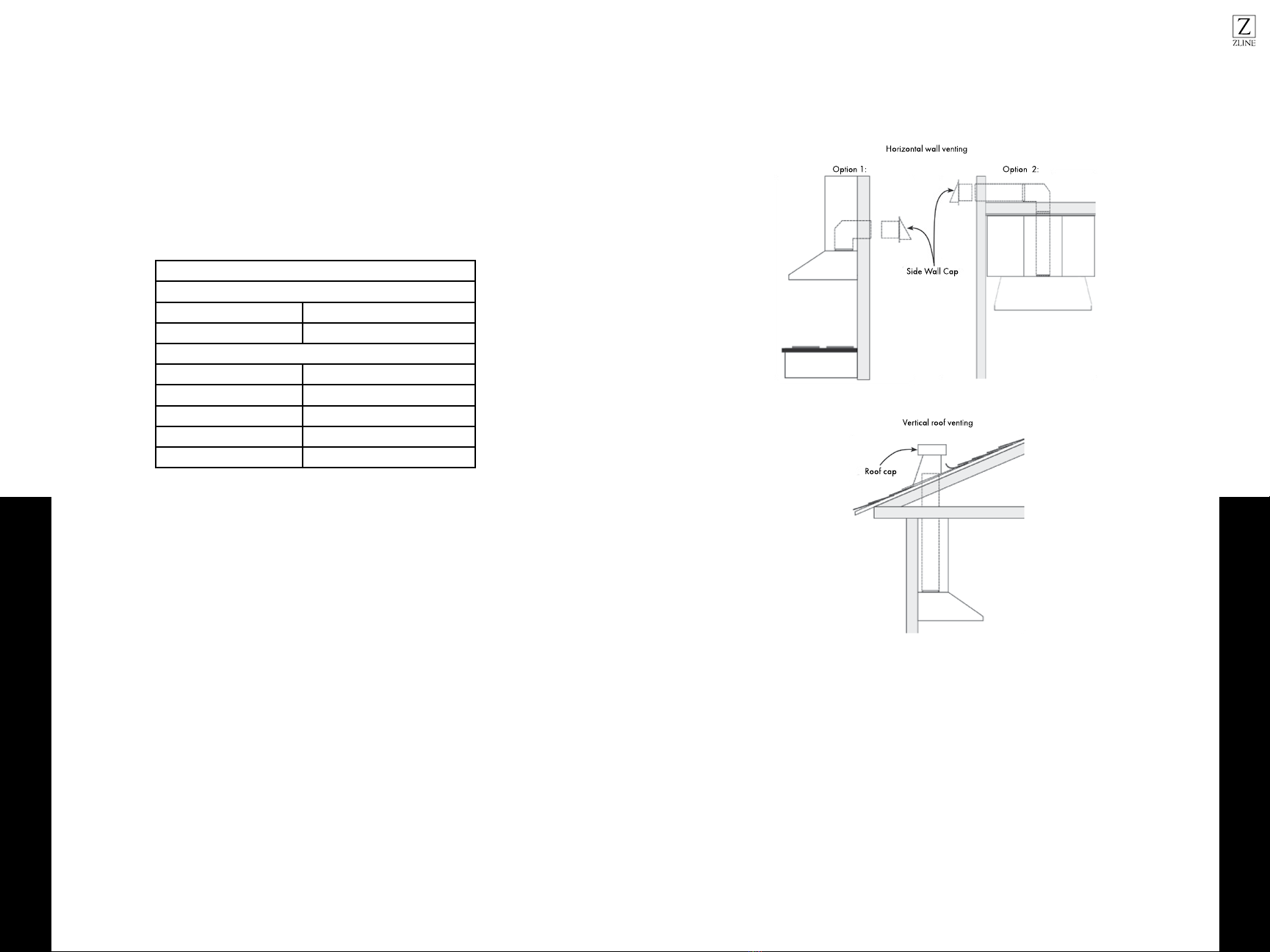
• Ducted fans MUST ALWAYS be vented to the outdoors. At the point where the
duct work ends, add an external damper to prevent air from entering the home
when the hood is not in use. This also prevents small animals and rain water from
entering the duct work.
• When cutting or drilling into a wall or ceiling, be careful not to damage electrical
wiring or other hidden utilities.
• Your safety and the safety of others is very important. We have provided many
important safety messages in this manual and on your appliance. Always
read and obey all safety messages. All safety messages will tell you what the
potential hazard is, tell you how to reduce the chance of injury, and tell you what
can happen if the instructions are not followed.
• All electrical wiring must be properly installed, insulated, and grounded.
• Old duct work should be cleaned or replaced, if necessary, to avoid the
possibility of a grease fire. Check all joints on duct work to insure proper
connection, all joints should be properly taped.
• Use this unit only in the manner intended by the manufacturer. If you have any
questions, contact the vendor.
• When the range hood ventilates the air out of the room, the air vented must be
replaced, this is called make-up air. If a makeup air system is needed, but not
used, a hood may not function as expected due to negative air pressure. We do
not currently provide a make-up air unit. Always consult any applicable building
codes in your area in regards to minimum and maximum air flow rates. Certain
states may require additional items such as make-up air for larger CFM range
hoods (typically over 300 CFM).
• Keep all fans, baffle, spaces, filter, grease tunnel, grease cup and grease-
laden surfaces clean. Grease should not be allowed to accumulate on fan,
baffle, spaces, filter, grease tunnel or grease cup. Clean grease-laden surfaces
frequently.
• To reduce the risk of fire and to disperse air properly, make sure to vent air
outside. DO NOT vent exhaust into spaces between walls, crawl spaces,
ceilings, attics or garages.

43
General Safety
SAFETY INSTRUCTIONS
• All ZLINE range hoods are ETL listed, ensuring all parts were tested for safety
and meet industry standards and regulations. NOTE: This ensures all included
plastic ducting pieces were tested for safety and are flame retardant.
• Always turn the range hood ON when cooking at high heat or when cooking
flaming foods. Use high settings on the cooking range only when necessary.
Never leave surface units unattended at high settings. Boil overs cause smoking
and greasy spillovers that may ignite. Heat oils slowly on low or medium settings.
• Clean ventilating fan frequently.
• Always use appropriate cookware and utensils size. Always use cookware
appropriate for the size of the surface element.
TO REDUCE THE RISK OF INJURY TO PERSONS IN THE EVENT OF A STOVE
TOP GREASE FIRE:
• Smother flames with a close fitting lid, cookie sheet or metal tray, then turn OFF
the burner. Never pick up a flaming pan—you may be burned.
• Keep flammable or combustible material away from flames. If the flames do not
go out immediately, evacuate and call the fire department. DO NOT use water,
including wet dishcloths or towels—a violent steam explosion will result.
Alpine Wall General Safety
This is the safety alert symbol. This symbol alerts you to potential hazards
that can hurt you and others. All safety messages will follow the safety
alert symbol and the word “WARNING”.
• The installation in this manual is intended for qualified installers, service
technicians, or persons with similar qualified background. Installation and
electrical wiring must be done by qualified professionals and in accordance with
all applicable codes and standards, including fire-rated construction.
• DO NOT attempt to install this appliance yourself. Injury could result from
installing the unit due to lack of appropriate electrical and technical background.
• Range hood may have very sharp edges; please wear protective gloves if it is
necessary to remove any parts for installing, cleaning, or servicing.
• Activating any switch “ON” before completing installation may cause ignition or
an explosion.
• Due to the size and weight of this range hood, a two person installation is
recommended.
• Clean ventilating fan frequently.
• Always use appropriate cookware and utensils size.
• Always use cookware appropriate for the size of the surface element.
TO REDUCE THE RISK OF FIRE, ELECTRIC SHOCK, OR INJURY TO PERSONS:
• For general ventilating use only. DO NOT use to exhaust hazardous or explosive
materials and vapors.
• The combustion air flow needed for safe operation of fuel-burning equipment
may be affected by this unit’s operation. Follow the heating equipment
manufacturer’s guideline and safety standards such as those published by
the National Fire Protection Association (NFPA), and the American Society of
Heating, Refrigeration and Air Conditioning Engineers (ASHRAE), and the local
code authorities.
• Before servicing or cleaning unit, switch power “OFF” at service panel and lock
service panel to prevent power from being switched ON accidentally.
• Clean grease laden surfaces frequently. To reduce the risk of fire and to disperse
air properly, make sure to vent air outside. DO NOT vent exhaust into spaces
between walls, crawl spaces, ceiling, attics, or garages.
WARNING
SAFETY INSTRUCTIONS
ALPINE WALL MODELS

65
Alpine Wall Venting Safety
Alpine Wall Fire Safety
• Ducted fans MUST always be vented to the outdoors.
• Use only metal ductwork and this unit MUST be grounded.
• Sufficient air is needed for proper combustion and exhausting of gases through
the duct to prevent back drafting.
• When cutting or drilling into wall or ceiling, be careful not to damage electrical
wiring and/or other hidden utilities.
• All electrical wiring must be properly installed, insulated, and grounded.
• Old duct work should be cleaned or replaced if necessary to avoid the
possibility of a grease fire.
• Check all joints on duct work to insure proper connection and all joints should be
properly taped.
• Use this unit only in the manner intended by the manufacturer. If you have
questions, contact ZLINE at 614-777-5004.
TO REDUCE RISK OF STOVETOP GREASE FIRE:
• Keep all fan, baffle, spaces, filter, grease tunnel, grease cup and grease-laden
surfaces clean. Grease should not be allowed to accumulate on fan, baffle,
spaces, filter, grease tunnel and grease cup.
• Always turn range hood ON when cooking at high heat or when cooking
flaming foods.
• Use high settings on cooking range only when necessary.
• Never leave surface units unattended at high settings. Boil overs cause smoking
and greasy spillovers that may ignite. Heat oils slowly on low or medium settings.
SAFETY INSTRUCTIONS
ALPINE WALL MODELS
SAFETY INSTRUCTIONS
ALPINE WALL MODELS
TO REDUCE THE RISK OF INJURY TO PERSONS IN THE EVENT OF A STOVE
TOP GREASE FIRE:
• SMOTHER FLAMES with a close-fitting lid, cookie sheet, or metal tray, then turn
OFF the burner.
• BE CAREFUL TO PREVENT BURNS. NEVER PICK UP A FLAMING PAN. You
may be burned.
• KEEP FLAMMABLE OR COMBUSTIBLE MATERIAL AWAY FROM FLAMES.
If the flames DO NOT go out immediately, EVACUATE AND CALL THE FIRE
DEPARTMENT or dial your local emergency service immediately.
• DO NOT USE WATER, including wet dishcloths or towels. A violent steam
explosion will result.
• Use an extinguisher ONLY if:
• You know you have a Class A, B, C extinguisher, and you already
know how to operate it.
• The fire is small and contained in the area where it is started.
• The fire department is being called.
• You can fight the fire with your back to an exit.
TO REDUCE THE RISK OF INJURY TO PERSONS IN THE EVENT OF A GAS
LEAKS:
• Extinguish any open flame.
• DO NOT turn on the range hood fan or any type of ventilator.
• DO NOT turn on the lights or any type of appliance.
• Open all doors and windows to disperse the gas. If you still smell gas, call
the gas company and fire department or dial your local emergency service
immediately.
Your safety and the safety of others is very important. We have provided many
important safety messages in this manual and on your appliance. Always read and
obey all safety messages. All safety messages will tell you what the potential hazard
is, tell you how to reduce the chance of injury, and tell you what can happen if the
instructions are not followed.

87
Alpine Wall Electrical Connection
Alpine Wall Tools
Utility knife
Flathead and
Philips screwdrivers
Upper chimney
Stainless steel baffle filter
Ducting transition
Lower chimney
Range hood
Optional duct tube
Powered screwdriver
or drill
Measuring tape Adjustable wrench
Pencil
Level
BEFORE INSTALLATION
ALPINE WALL MODELS
TOOLS NEEDED:
INCLUDED PARTS:
ELECTRICAL REQUIREMENTS
• Contact a qualified electrical installer.
• Assure that the electrical installation is adequate and in conformance with Na-
tional Electrical Code, ANSI/NFPA 70 — latest edition, or CSA Standards C22.
1-94, Canadian Electrical Code, Part 1 and C22. 2 No. 0-M91 - latest edition
and all local codes and ordinances.
• If codes permit and a separate ground wire is used, it is recommended that a
qualified electrician determine that the ground path is adequate.
• A 110~120V/60Hz, AC-only, fused electrical supply is required on a separate
15-amp circuit, fused on both sides of the line.
• Do not ground to a gas pipe.
• Check with a qualified electrician if you are not sure that the range hood is
properly grounded.
• Do not have a fuse in the neutral or ground circuit.
• IMPORTANT: Save manual for electrical inspector’s use.
• The range hood must be connected with copper wire/plug only.
• The range hood should be connected directly to the fused disconnect (or circuit
breaker) box through flexible armored or non-metallic sheathed copper cable.
A U.L. - or C.S.A. - listed strain relief must be provided at each end of the power
supply cable.
• Wire sizes (COPPER WIRE ONLY) and connections must conform with the rating
of the appliance as specified on the model/serial rating label. Wire sizes must
conform to the requirements of the National Electrical Code ANSI/NFPA 70 —
latest edition*, or CSA Standards C22. 1-94, Canadian Electrical Code Part 1
and C22. 2 No. 0-M91 - latest edition and all local codes and ordinances. A
U.L. - or C.S.A. - listed conduit connector must be provided at each end of the
power supply cable (at the range hood and at the junction box).
• Copies of the standards listed may be obtained from:
BEFORE INSTALLATION
ALPINE WALL MODELS
CSA International
8501 East Pleasant Valley Road
Cleveland, Ohio 44131-5575
National Fire Protection Association
Batterymarch Park
Quincy, Massachusetts 02269

109
Alpine Wall Venting
Alpine Wall Venting
ADVANCED PREPARATIONS
1. Be familiar with the controls of the range hood by reading through the Range
Hood Operations, page 40.
2. Place the range hood on a flat, stable surface. Connect the range hood to a
designated standard outlet, 110~120V/60Hz, AC only, and turn on the range
hood. Verify all operations of the range hood by referring to the Range Hood
Operations, page 40.
3. Place all supplied parts and required hardware on a flat, stable surface and
verify the existence of all supplied parts listed on page 31.
4. Carefully remove the white plastic protective coat from the chimney covers and
range hood.
VENTING REQUIREMENTS
Vent system must terminate to the outside (roof or
side wall).
• DO NOT terminate the vent system in an attic
or other enclosed area.
• Do not reduce wall cap size. It can be bigger
than the ducting size, but not smaller.
• Use metal/aluminum vent only. Rigid metal/
aluminum vent is recommended.
• DO NOT use plastic vent.
• Always keep the duct clean to ensure proper
airflow.
• Calculate the following figures before
installation:
• Distance from the floor to the
ceiling.
• Distance between the floor to the
countertop/stove
(recommend 28” to 31”).
• Distance between the
countertop/stove to the
range hood.
• Height of hood and duct cover.
BEFORE INSTALLATION
ALPINE WALL MODELS
Under Cabinet
Range Hood
Countertop/Stove
Cabinet or Single-Piece
Chimney (optional)
36”
Counter
Top
Ceiling
Height
Min: 28”
Max: 31”
Range
Hood
Height
Cabinet
Height
FOR THE MOST EFFICIENT & QUIET OPERATION
• A distance of 28” to 31” is recommended between stove top and the bottom of
range hood.
• It is recommended that the range hood be vented vertically through the roof
through 8” or bigger round metal/aluminum vent work.
• The size of the vent should be uniform.
• Use no more than three 90° elbows. The length of vent system and number of
elbows should be kept to a minimum to provide efficient performance.
• Make sure there is a minimum of 24” of straight vent between the elbows if more
than one elbow is used.
• DO NOT install two elbows together.
• The vent system must have a damper. If roof or wall cap has a damper, DO NOT
use damper (if supplied) on top of the range hood.
• Use silver tape to seal all joints in the vent system.
• Use caulking to seal exterior wall or roof opening around the cap.
IMPORTANT:
A minimum of 6” round (standard for this range hood) or 3-1/4 x 10” rectangular
duct (purchased separately) must be used to maintain maximum airflow efficiency.
• Always use rigid type metal/aluminum ducts, if available, to maximize airflow
when connecting to provided duct.
• Please use Duct Run Calculation below to calculate total available duct run
when using elbows, transitions and caps.
• ALWAYS, when possible, reduce the number or transitions and turns. If long duct
run is required, increase duct size from 8” to 9” or 10”. If a reducer is used,
install a long reducer instead of a pancake reducer.
• Reducing duct size will restrict airflow and decrease airflow, thus reduce duct
size as far away from opening as possible.
• If turns or transitions are required: Install as far away from opening and as far
apart, between 2, as possible.
• Minimum mount height between stove top to hood bottom should be no less than
28-inch*. Maximum mount height between stove top to hood bottom should be
no higher than 31-inch*.
• It is important to install the hood at the proper mounting height. Hoods mounted
too low could result in heat damage and fire hazard; while hoods mounted too
high will be hard to reach and will loose its performance and efficiency.
• If available, also refer to stove top manufacturer’s height clearance requirements
and recommended hood mounting height above range.
BEFORE INSTALLATION
ALPINE WALL MODELS

1211
Alpine Wall Preparations
Alpine Wall Venting
Due to different ceiling height configurations, recommended height may not be
applicable.
CALCULATING VENT SYSTEM LENGTH
To calculate the length of the system you need, deduct the equivalent feet for each
vent piece used in the system from the recommended maximum duct run.
DUCT RUN CALCULATION
Recommended maximum run
8” or 3-1/4 x 10” duct 50 ft
Vent piece deduction
9 ft
Paper bags 5 ft
Plastic foam 7 ft
Wood 0 ft
Roof cap 0 ft
Duct Run Calculation example:
One roof cap, two 90° elbow, and one 45° elbow used:
0 ft + 9 ft + 9 ft + 5 ft = 23 ft used.
Deduct 23 ft from 50 ft, 27 ft maximum available for straight duct run.
VENTING METHODS
This range hood is factory set for venting through the roof or wall. Vent work can
terminate either through the roof or wall. To vent through a wall, use a 90° elbow.
IMPORTANT:
• NEVER exhaust air or terminate duct work into spaces between walls, crawl
spaces, ceiling, attics or garages. All exhaust must be ducted to the outside.
• Use metal/aluminum duct work only.
• Fasten all connections with sheet metal screws and tape all joints with certified
silver tape.
• Use caulking to seal exterior wall or roof opening around the cap.
WARNING: Moving and installing the range hood is a two person job. Spinal or
other bodily injuries could occur if it is not followed.
BEFORE INSTALLATION
ALPINE WALL MODELS
PREPARATIONS
1. Determine and mark the center line on the ceiling where the range hood will
be installed. Make sure there is proper clearance within the ceiling or wall for
exhaust vent.
2. Due to the weight and size of this unit, make sure that the support system or
framework being used is stable and secure in the wall.
3. Put a thick, protective covering over counter top, cook top, or range to protect
it from damage or dirt. Remove any hazardous objects around the area when
installing.
Side Wall Cap
Horizontal wall venting
Vertical roof venting
Roof cap
Option 1: Option 2:
Side Wall Cap
Horizontal wall venting
Vertical roof venting
Roof cap
Option 1: Option 2:
BEFORE INSTALLATION
ALPINE WALL MODELS

1413
Alpine Wall Preparation
Alpine Wall Installation
4. Mark the locations of the support mounting bracket holes, vent cutout (if used),
and power supply cable cutout on the ceiling. Use drill and saber saw or
keyhole saw to cut openings for power supply cable and vent (see Venting
requirements and Electrical requirements, pages 32-36).
5. If venting to the outside install vent system (see Venting Requirements, page 33,
use caulking to seal exterior wall or roof openings.
6. Disconnect main electrical supply, prepare, and run electrical wiring through
ceiling or wall. Leave approximately 12” of electrical cord hanging from the
ceiling. Do not restore power until wiring is completed.
7. Disconnect power cord, remove the stainless steel filters by pulling down toward
the direction of solid arrow while holding both of the metal handles, and gently
pull the stainless steel filters toward the direction of dashed arrow as shown in
Figure 1.
8. Remove the grease cup by sliding it sideways, see Figure 2 for location of the
grease cup.
9. Set aside the stainless steel filters and grease cup until the range hood is properly
installed.
10. If the range hood comes with a glass canopy and has not already been mounted
to the hood, loosen the four canopy screws and washers from the hood top,
carefully place the canopy on the hood top, and loosely tighten the four canopy
screws along with washers. DO NOT put excessive pressure against the glass.
WARNING: Severe Injury Rotating fan can cause severe injury. Stay clear of fan
when motor is running
Figure 1 Figure 2
WARNING: HAZARD OF ELECTRIC SHOCK
Do not perform service on an electrically live system. Disconnect the main electrical
supply before servicing this device. Touching electrical connectors or other exposed
electrical circuitry inside this range hood when they are energized could result in
death, serious bodily injury, or property damage.
1. Measure the distance between stove top and the bottom of range hood. A dis-
tance of 28” to 31” is required.
2. Make sure the range hood is level and not tilted. Mark the locations of the hang-
ing bracket holes on the wall as shown in Figure 3A and Figure 3B.
3. Place the mounting bracket directly above the range hood, level it, and mark the
locations of the mounting bracket holes on the wall.
4. Place aside all equipments, locate marked regions and drill holes. Attach range
hood to wall using anchors recommended for your type of wall:
• Sheet rock wall: Attach range hood to stud blockings if possible. If stud
blockings are not available, it is required to build a supporting structure
behind the sheet rock for best weight support.
• Concrete wall: Use designated screws (not provided).
• Wood wall: Use at least 5 cm long wood screws (not provided).
5. Fasten two Type “A” anchors (for range hood and for mounting bracket or air
diverted) on the wall as shown in Figure 4. Loosely fasten two Type “B” screws
onto anchors, DO NOT fasten screws all the way. Hang the range hood on the
Type “B” screws and hand tighten them. Leave approximately 1/8” of gap from
the wall to the range hood.
6. Place the mounting bracket against the wall and align the holes from mounting
bracket with holes from Type “A” anchors, fasten two Type “B” screws through
the holes onto the anchors as shown in Figure 5. Leave approximately 1/8” of
gap from the wall to the mounting bracket.
Figure 4
Figure 3B
Figure 3A
Figure 5
Secure
Upper
Support
Frame
Fasten
mounting
bracket
Slide up and secure
upper chimney to
mounting bracket
Hold in position and
secure lower chimney
to range hood
BEFORE INSTALLATION
ALPINE WALL MODELS
INSTALLATION
ALPINE WALL MODELS

1615
Alpine Wall Installation
Alpine Wall Operation
7. Calculate the height of the duct tube and extend approximately 6” (15 cm)
longer than required, connect the lower end of the duct tube to the range hood
and the upper end to the vent system. Make sure the main electrical supply
remains disconnected then connect power plug to the electrical cord or wall
plug.
8. Have one person carefully position both upper and lower chimneys on the range
hood, let the second person slide the sides of the chimneys into the 1/8” gap.
Fasten both chimneys with four Type “C” screws.
9. Install grease cup and aluminum filters then check the operation of the range
hood.
Mounting bracket
Upper chimney
Lower chimney
6” round duct (exhaust)
Wall mounted range hood
A1+B1
A1+B1
A1+B1
A1+B1
C
C
C
C
INSTALLATION
ALPINE WALL MODELS
OPERATION
ALPINE WALL MODELS
• Power: Turn ON/OFF the range hood and activate power-off delay timer
(3mins).
• Low Speed: Light frying/boiling.
• Medium Speed: Frying/wok cooking/heavy boiling.
• High Speed: Intensive frying and wok cooking.
• Light: Turn ON/OFF
Adjusting the blower (motor) speed: Press the power key then press any speed
buttons one time , the blower will start at any speed, press same button again , shut
down the blower.
Adjusting the timer function: Turn the hood on at any speed and press the power-off
delay button one time, it will enter timer mode, power-off delay digital timer will
begin countdown. Press again ,the blower will shut down.
Never put your hand into area housing the fan while the fan is operating!
The remote control is a 433M high frequency remote control.
The distance of the remote control is 10 meters. The signal can
pass through the wall.
It needs to match code with the hood to use it for the first time.
Press Lamp key on range hood for 5 seconds. Once the light
of the lamp button on the hood flickers, press any button on
the remote control. If the LED of lamp button stops flickering,
the matching is done.

1817
• If hood looks splotchy, use a stainless steel cleaner to clean the surface of
the hood. Avoid getting cleaning solution on or into the control panel. Follow
directions of the stainless steel cleaner. CAUTION: Do NOT leave on too long
as this may cause damage to hood finish. Use soft towel to wipe off the cleaning
solution, gently rub off any stubborn spots. Use dry soft towel to dry the hood.
• After cleaning, you may use non-abrasive stainless steel polish such as 3M ® or
ZEP®, to polish and buff out the stainless luster and grain. Always scrub lightly,
with clean cotton cloth, and with the grain.
• Do NOT allow deposits to accumulate or remain on the hood.
• Do NOT use ordinary steel wool or steel brushes. Small bits of steel may adhere
to the surface and cause rusting.
• Do NOT allow salt solutions, disinfectants, bleaches, or cleaning compounds
to remain in contact with stainless steel for extended periods. Many of these
compounds contain chemicals which may be harmful. Rinse with water after
exposure and wipe dry with a clean cloth.
• Cleaning grease filter/stainless steel filter: IMPORTANT: Drain oil from oil
containers before oil and residue overflow!
• The metal filters fitted by the factory are intended to filter out residue and grease
from cooking. They do not need to be replaced on a regular basis but are
required to be kept clean.
• Filters should be cleaned after every 30 hours of use. Remove and clean by
hand or dishwasher. Use proper degreasing detergent for stainless steel and
leave to soak if heavily soiled. Dry filters and re-install before using hood.
Alpine Wall Operation
MAINTENANCE AND CLEANING
ALPINE WALL MODELS
MAINTENANCE AND CLEANING
ALPINE WALL MODELS
HOW TO CHANGE OR REPLACE LIGHT BULB
1. Make sure the range hood is unplugged or turn OFF breaker.
2. Slightly press inward on the bulb using both thumbs.
3. Keep your grip & pressure constant on the bulb with the thumbs as you turn
the bulb counter-clockwise. Stop pushing it inward once you feels it won’t turn
further (it should turn about 90 degrees)
4. Pull the bulb straight out of the socket
5. Have new light bulb legs to align with 2 socket base slot holes
6. Press the new bulb inward into the socket. You will press the bulb inward into the
same position that you took the old bulb out from. Twist it clockwise as far as it
will go, and you can turn the lights back on
CLEANING
• The saturation of greasy residue in the blower and filters may cause increased
inflammability. Keep unit clean and free of grease and residue buildup at all
times to prevent possible fires.
• FILTERS MUST BE CLEANED PERIODICALLY AND FREE FROM
ACCUMULATION OF COOKING RESIDUE.
• Do NOT operate blowers when filters are removed. Never disassemble parts to
clean without proper instructions.
• Disassembly is recommended to be performed by qualified personnel only. Read
and understand all instructions and warnings in this manual before proceeding.
• For optimal operation, clean range hood and all baffle/spacer /filter/grease
tunnel/oil container regularly. Regular care will help preserve the appearance
of the range hood.
CLEANING EXTERIOR SURFACES:
• Clean periodically with stainless steel cleaner or hot soapy water and clean
cotton cloth. Do NOT use corrosive or abrasive detergent (e.g. Comet Power
Scrub®, EZ-Off® oven cleaner), or steel wool/scouring pads, which will scratch
and damage the stainless steel surface. For heavier soil, use liquid degrease such
as “Formula 409®” or “Fantastic®” brand cleaner.

2019
Alpine Wall Troubleshooting
TROUBLESHOOTING
ALPINE WALL MODELS
FAULT TROUBLESHOOTING
Range hood does
not operate after
installation
Check if the range hood has been plugged in. Make sure
that all power has been turned back on and all electrical
wiring is properly connected.
Swap out light assembly to working ones to determine
whether it is caused by defective bulbs. (See Replacing the
light bulbs, page 16)
Range hood
vibrates when the
blower is on
The range hood might not have been secured properly on to
the ceiling.
Check if the blower wheel is damaged.
The blowers seems
weak
Check that the duct sized used is at least 6”. Range hood
WILL NOT function efficiently with insufficient duct size and
loosely secured.
Check if duct is clogged or if damper unit is not opening
properly. A tight mesh on a side wall cap unit might also
cause restriction to the airflow.
The lights work, but
the blower is not
spinning at all, is
stuck, or is rattling.
The blower might be jammed or scraping the bottom due to
shipping damage.
The hood is not
venting out properly
Make sure the distance between the cook top and the bot-
tom of the hood is within 26” and 30” in range.
Reduce the number of elbows and length of duct work.
Check if all joints are properly connected, sealed, and
taped.
Make sure the power is on high speed for heavy cooking
The hood is nosier
than normal
The damper was not opened
The duct is not secure and causes vibration
The smaller duct size than required is being used
ZLINE Customer Service is available at 1-614-777-5004.
Alpine Under Cabinet General Safety
This is the safety alert symbol. This symbol alerts you to potential hazards
that can hurt you and others. All safety messages will follow the safety alert
symbol.
TO REDUCE THE RISK OF FIRE, ELECTRIC SHOCK, OR INJURY, PLEASE
OBSERVE THE FOLLOWING:
1. Installation work and electric wiring (including switch location) must be done by
qualified person(s) in accordance with local applicable codes and standards,
including fire-rated construction.
2. This hood may have sharp edges. Be careful to avoid cuts and abrasions during
installation and cleaning.
3. The hood must be placed at a minimum distance of 24” from the stovetop.
4. Sufficient air is needed for proper combustion and exhausting of gases through
the chimney of fuel burning equipment to prevent backdrafting. Follow the
heating equipment manufacturer’s guideline and safety standards, such as those
published by the National Fire Protection Association, and the American Society
for Heating, Refrigeration and Air Conditioning Engineer (ASHRAE), and the
local code authorities.
5. Ducted fans must always be vented to the outdoors.
6. This appliance is design to be operated by adults.
7. WARNING: To reduce the risk of fire or electric shock,do not use this fan with
any solid-state speed control device.
8. When cutting or drilling into wall or ceiling, do not damage electrical wiring and
other hidden utilities.
SAFETY INSTRUCTIONS
ALPINE UNDER CABINET MODELS
WARNING
Alpine Under Cabinet Safety

2221
Alpine Under Cabinet Fire Safety
WARNING: TO REDUCE THE RISK OF FIRE, USE ONLY THE METAL
DUCTWORK.
WARNING: TO REDUCE THE RISK OF INJURY TO PERSONS IN THE
EVENT OF A RANGE TOP FIRE, OBSERVE THE FOLLOWING:
1. SMOTHER FLAMES with a close-fitting lid, cookie sheet, or metal tray, then turn
off the burner. BE CAREFUL TO PREVENT BURNS. If the flames do not go out
immediately, EVACUATE AND CALL THE FIRE DEPARTMENT.
2. NEVER PICK UP A FLAMING PAN. You may be burned.
3. DO NOT USE WATER, including wet dishcloths or towels. A violent steam
explosive will result.
4. Use an extinguisher ONLY if:
• You know you have a Class ABC extinguisher and you already know
how to operate it.
• The fire is small and contained in the area where it started.
• The fire department is being called.
• You can fight the fire with your back to an exit.
WARNING: TO REDUCE THE RISK OF A RANGE TOP GREASE FIRE:
1. Never leave surface units unattended at high settings. Boilovers cause smoking
and greasy spillovers that may ignite. Heat oils slowly on low or medium settings.
2. Always turn hood ON when cooking at high heat or when flambeing food (i.e.
Crepes Suzette, Cherries Jubilee, Peppercorn Beef Flambé).
3. Clean ventilating fans frequently. Grease should not be allowed to accumulate
on fan or filter.
4. Use proper pan size. Always use cookware appropriate for the size of the
surface element.
SAFETY INSTRUCTIONS
ALPINE UNDER CABINET MODELS
WARNING
WARNING
WARNING
Alpine Under Cabinet Installation Safety
WARNING: TO REDUCE THE RISK OF FIRE, ELECTRIC SHOCK, OR
INJURY, OBSERVE THE FOLLOWING:
• Use this unit only in the manner intended by this manual. If you have questions,
contact ZLINE at 614-777-5004.
• Before servicing or cleaning unit, switch power off at the service panel and
disconnect the unit. This will prevent power from being switched on accidentally.
Securely fasten a prominent warning device, such as a tag, to the service panel.
RECOMMENDATIONS AND SUGGESTIONS: INSTALLATION
Before the final installation is made, check that all parts are in the box. Check the
finish of the range hood for scratches or dents. Check the operation of the range
hood. If there are any issues, do not install the range hood. Call ZLINE at 614-777-
5004.
The manufacturer will not be held liable for any damage resulting from incorrect or
improper installation.
• Please read this instruction manual before installing and using this range hood.
Keep this instruction manual in a safe place for future reference.
• This range hood can be used only in a ducted mode (ducting fumes to the
outside).
• Only a qualified and trained service technician should install and service the
unit.
• Check that the main voltage corresponds to the one indicated on the rating plate
fixated inside the hood.
• Check that the domestic power supply guarantees adequate grounding.
• Do not connect the hood to exhaust ducts carrying combustion fumes (boilers,
fireplaces, etc.)
• If the hood is used in conjunction with non-electrical appliances (e.g. gas
burning appliances), a sufficient degree of aeration must be guaranteed in the
room in order to prevent the backflow of exhaust gas. The kitchen must have an
opening directly with the open air in order to guarantee the entry of clean air.
• The minimum distance is 30”-32” from the range hood to a gas hob and is
24”-30” to an electric hob. If the installation instructions for gas hobs specify a
greater distance, this must be taken into account.
WARNING
SAFETY INSTRUCTIONS
ALPINE UNDER CABINET MODELS
Alpine Under Cabinet Safety

2423
Alpine Under Cabinet Electrical Connection
NOTICE: Considering excessive weight, two or more people are required to install or
move this appliance. Failure to do so can cause physical injuries.
GROUNDING INSTRUCTIONS
15amp, 120V, 60Hz
This appliance must be grounded. The range hood is equipped with a cord having a
grounding wire with a grounding plug. The plug must be plugged into an outlet that is
properly installed and grounded.
WARNING: Improper grounding can result in a risk of electric shock.
Consult a qualified electrician if the grounding instructions are not completely
understood or if doubt exists as to whether the appliance is properly grounded.
Do not use an extension cord. If the power supply is too short, have a qualified
electrician install an outlet near the appliance.
PREPARE THE HOOD
Unpack hood and check contents. You should receive:
1. Hood
2. Installation Instructions
3. Aluminum Flex Duct
4. Parts Bag containing:
Mounting bracket
QTY: 2
Hose clamp
QTY: 1
Explode Screws
QTY: 2
M4*12
QTY: 4
Mounting bracket
QTY: 2
Hose clamp
QTY: 1
Explode Screws
QTY: 2
M4*12
QTY: 4
Mounting bracket
QTY: 2
Hose clamp
QTY: 1
Explode Screws
QTY: 2
M4*12
QTY: 4
Mounting bracket
QTY: 2
Hose clamp
QTY: 1
Explode Screws
QTY: 2
M4*12
QTY: 4
Mounting bracket
QTY: 2
Hose clamp
QTY: 1
Explode Screws
QTY: 2
M4*12
QTY: 4
WARNING
WARNING
Hose clamp
QTY: 1
Mounting bracket
QTY: 2
Aluminum Flex Duct
QTY: 1
Explode screws
QTY: 2
M4*12
QTY: 4
BEFORE INSTALLATION
ALPINE UNDER CABINET MODELS
Alpine Under Cabinet Venting Specifications
Roof cap
Duct (for vertical discharge)
Duct (for horizontal discharge)
Wall cap
House wiring
Cabinet
Hood
24”-30” (Electric hob)
30”-32” (Gas hob)
Ply wood or
solid flatform
Wood block
approx 2.” thick
30”/36”/42”
28.4”/34.7”/41”
10”
2”
22”
12”
8”
NOTE: Carefully remove the plastic protective film from exterior of the surfaces of
the hood prior to final installation.
CAUTION: To reduce risk of fire and electric shock, install this range
hood only with integral blowers by qualified person or agency.
WARNING: TO REDUCE THE RISK OF FIRE, ELECTRIC SHOCK, OR
INJURY, OBSERVE THE FOLLOWING:
1. Installation work and electrical wiring must be done by qualified person(s)
in accordance with all applicable code and standards, including fire-rated
construction.
2. Sufficient air is needed for proper combustion and exhausting of gases through
the flue (chimney) of fuel burning equipment to prevent back drafting. Follow
the heating equipment manufacturer’s guideline and safety standards, such as
those published by the National Fire Protection Association (NFPA), and the
local code authorities.
3. When cutting or drilling into the wall or ceiling, do not damage electrical wiring
and/or other hidden utilities.
4. Ducted fans must always be vented to the outdoors.
CAUTION
WARNING
BEFORE INSTALLATION
ALPINE UNDER CABINET MODELS
Alpine Under Cabinet Tools
Alpine Under Cabinet Preparation

2625
Alpine Under Cabinet Venting Specifications
1.
Roof cap
Duct (for vertical discharge)
Duct (for horizontal discharge)
Wall cap
House wiring
Cabinet
Hood
24”-30” (Electric hob)
30”-32” (Gas hob)
Ply wood or
solid flatform
Wood block
approx 2.” thick
30”/36”/42”
28.4”/34.7”/41”
10”
2”
22”
12”
8”
The hoods feature a 8” top round opening. Run ductwork between the hood
location and roof cap. For the results, use a minimum number of transitions and
elbows.
2. Use the diagram above for placement of ductwork and electrical cutout in
cabinet or wall.
WARNING: To avoid the risk of fire, use only the metal ductwork.
WARNING
BEFORE INSTALLATION
ALPINE UNDER CABINET MODELS
Alpine Under Cabinet Installation
STEP 1: PROTECT THE COOKTOP
Put a thick, protective covering over counter top, cook top, or range to protect it from
damage or dirt.
STEP 2: CREATE WORK STATION (OPTIONAL)
Roof cap
Duct (for vertical discharge)
Duct (for horizontal discharge)
Wall cap
House wiring
Cabinet
Hood
24”-30” (Electric hob)
30”-32” (Gas hob)
Ply wood or
solid flatform
Wood block
approx 2.” thick
30”/36”/42”
28.4”/34.7”/41”
10”
2”
22”
12”
8”
Put two pieces of wood, about 2” x 4” x 20”, on both sides of stove. Put plywood on
top of them to protect the cook top or stove from damage or dirt. This plywood also
creates a comfortable work station for easy installation.
STEP 3: PREPARE DUCTWORK & SINGLE OUTLET
•
8” aluminium flex duct
8” metal duct 15A, 120V, single outlet
Top View of Actual Hood
Bottom cabinet
2” wide2” wide
B
A
Range hood
Ply wood on
solid flatform
Cabinet jack
or car jack
Wood block
approx. 2” thick
Flush with the front frame of cabinet
Make sure you have a 15amp, 120V, 60Hz, single outlet on the left or right of
the duct pipe (usually is on ¼ of cabinet width).
• Make sure duct pipe is ready to hook up to the range hood before beginning
installation (8” diameter duct and roof or wall cap, depending on where the
hood will be vented.)
INSTALLATION
ALPINE UNDER CABINET MODELS
Alpine Under Cabinet Preparation
Alpine Under Cabinet Installation

2827
Alpine Under Cabinet Installation
STEP 4: ATTACH 2” WIDE WOOD FILLER STRIPS
8” aluminium flex duct
8” metal duct 15A, 120V, single outlet
Top View of Actual Hood
Bottom cabinet
2” wide2” wide
B
A
Range hood
Ply wood on
solid flatform
Cabinet jack
or car jack
Wood block
approx. 2” thick
Flush with the front frame of cabinet
For installing under the cabinet with a recessed bottom, attach 2-inch wide wood
filler strips.
STEP 5: CREATE ACCESS
8” aluminium flex duct
8” metal duct 15A, 120V, single outlet
Top View of Actual Hood
Bottom cabinet
2” wide2” wide
B
A
Range hood
Ply wood on
solid flatform
Cabinet jack
or car jack
Wood block
approx. 2” thick
Flush with the front frame of cabinet
Create an opening for the electrical wire and hood exhaust under the cabinet.
STEP 6: ATTACH THE HOOD
8” aluminium flex duct
8” metal duct 15A, 120V, single outlet
Top View of Actual Hood
Bottom cabinet
2” wide2” wide
B
A
Range hood
Ply wood on
solid flatform
Cabinet jack
or car jack
Wood block
approx. 2” thick
Flush with the front frame of cabinet
Lift the hood up and place it below the cabinet. Make sure to center the hood
beneath the cabinet. Make sure that it is flush with the front of the cabinet.
NOTE: A cabinet or a car jack is highly recommended due to the weight of the hood.
INSTALLATION
ALPINE UNDER CABINET MODELS
STEP 7: SECURE THE HOOD TO BOTTOM CABINET
8” aluminium flex duct
8” metal duct 15A, 120V, single outlet
Top View of Actual Hood
Bottom cabinet
2” wide2” wide
B
A
Range hood
Ply wood on
solid flatform
Cabinet jack
or car jack
Wood block
approx. 2” thick
Flush with the front frame of cabinet
From inside of the hood, use the “hex bit extension.” Place 1 ¼” screw (provided) into
A. Each key hole
OR
B. Predrilled-holes
and secure to cabinet bottom. There are 8 holes (4 keyholes & 4 predrilled-holes)
available. You can use either the key or predrilled-holes as long as there is a minimum
of one screw at each corner of hood body.
STEP 8: CONNECT ALUMINUM FLEX DUCT AND DUCTWORK
•
8” aluminium flex duct
8” metal duct 15A, 120V, single outlet
Top View of Actual Hood
Bottom cabinet
2” wide2” wide
B
A
Range hood
Ply wood on
solid flatform
Cabinet jack
or car jack
Wood block
approx. 2” thick
Flush with the front frame of cabinet
8” aluminum flex duct attaches to the hood directly
• Connect the aluminum flex duct to ductwork and wrap with aluminum tape to
make all the joints secure and tight.
NOTE: The quality of the duct should meet the local law and fire prevention standards.
INSTALLATION
ALPINE UNDER CABINET MODELS
Alpine Under Cabinet Installation

3029
STEP 9: INSTALL OIL TUNNEL OR Grease cup (NOT AVAILABLE FOR ALL
MODELS)
Stop
Low
Mid
High
Light
Oil tunnel
Side view
BACKFRONT
SIDE VIEW: Baffle installation
Drop oil tunnel into recess support near rear of hood. Refer to the image above.
STEP 10 INSTALL BAFFLE FILTERS
Stop
Low
Mid
High
Light
Oil tunnel
Side view
BACKFRONT
SIDE VIEW: Baffle installation
Install baffle filters. Refer to the image above for the following the first three steps:
NOTE: The middle filter has to be installed last where it should be taken out first when
you want to remove other filters.
1. Angle baffle filter toward back of hood.
2. Lift the baffle filter up above horizontal level.
3. Slide forward into slot towards the front of the hood.
4. Slide the installed baffle filter to either left or right until it stops.
5. Repeat step 1 to 4 to install the next set. Make sure you slide to opposite
direction from the previous installed filter.
To remove the baffle, please the process.
INSTALLATION
ALPINE UNDER CABINET MODELS
Alpine Under Cabinet Installation
Alpine Under Cabinet Keys
OPERATION
ALPINE UNDER CABINET MODELS
Alpine Under Cabinet Keys
• Power: Turn ON/OFF the range hood and activate power-off delay timer
(3mins).
• Low Speed: Light frying/boiling.
• Medium Speed: Frying/wok cooking/heavy boiling.
• High Speed: Intensive frying and wok cooking.
• Light: Turn ON/OFF
Adjusting the blower (motor) speed: Press the power key then press any speed
buttons one time , the blower will start at any speed, press same button again , shut
down the blower.
Adjusting the timer function: Turn the hood on at any speed and press the power-off
delay button one time, it will enter timer mode, power-off delay digital timer will
begin countdown. Press again ,the blower will shut down.
Never put your hand into area housing the fan while the fan is operating!
The remote control is a 433M high frequency remote control.
The distance of the remote control is 10 meters. The signal can
pass through the wall.
It needs to match code with the hood to use it for the first time.
Press Lamp key on range hood for 5 seconds. Once the light
of the lamp button on the hood flickers, press any button on
the remote control. If the LED of lamp button stops flickering,
the matching is done.
Alpine Under Cabinet Installation
Alpine Under Cabinet Operation

3231
Alpine Under Cabinet Maintenance & Cleaning
MAINTENANCE AND CLEANING
ALPINE UNDER CABINET MODELS
HOW TO CHANGE OR REPLACE LIGHT BULB
1. Make sure the range hood is unplugged or turn OFF breaker.
2. Slightly press inward on the bulb using both thumbs.
3. Keep your grip and pressure constant on the bulb with your thumbs as you turn
the bulb counter-clockwise. Stop pushing it inward once you feels it won’t turn
further (it should turn about 90 degrees).
4. Pull the bulb straight out of the socket.
5. Align the new light bulb legs with the two socket base slot holes.
6. Press the new bulb inward into the socket. Press the bulb inward into the same
position that you took the old bulb out from. Twist it clockwise as far as it will go
and you can turn the lights back on.
CLEANING
• The saturation of greasy residue in the blower and filters may cause increased
inflammability. Keep unit clean and free of grease and residue buildup at all
times to prevent possible fires.
• FILTERS MUST BE CLEANED PERIODICALLY AND FREE FROM
ACCUMULATION OF COOKING RESIDUE.
• Do NOT operate blowers when filters are removed. Never disassemble parts to
clean without proper instructions.
• Disassembly is recommended to be performed by qualified personnel only. Read
and understand all instructions and warnings in this manual before proceeding.
• For optimal operation, clean range hood and all baffle/spacer /filter/grease
tunnel/oil container regularly. Regular care will help preserve the appearance
of the range hood.
CLEANING EXTERIOR SURFACES:
• Clean periodically with stainless steel cleaner or hot soapy water and clean
cotton cloth. Do NOT use corrosive or abrasive detergent (e.g. Comet Power
Scrub®, EZ-Off® oven cleaner), or steel wool/scouring pads, which will scratch
and damage the stainless steel surface. For heavier soil, use liquid degrease such
as “Formula 409®” or “Fantastic®” brand cleaner.
• If hood looks splotchy, use a stainless steel cleaner to clean the surface of
the hood. Avoid getting cleaning solution on or into the control panel. Follow
directions of the stainless steel cleaner. CAUTION: Do NOT leave on too long
as this may cause damage to hood finish. Use soft towel to wipe off the cleaning
solution, gently rub off any stubborn spots. Use dry soft towel to dry the hood.
• After cleaning, you may use non-abrasive stainless steel polish such as 3M ® or
ZEP®, to polish and buff out the stainless luster and grain. Always scrub lightly,
with clean cotton cloth, and with the grain.
• Do NOT allow deposits to accumulate or remain on the hood.
• Do NOT use ordinary steel wool or steel brushes. Small bits of steel may adhere
to the surface and cause rusting.
• Do NOT allow salt solutions, disinfectants, bleaches, or cleaning compounds
to remain in contact with stainless steel for extended periods. Many of these
compounds contain chemicals which may be harmful. Rinse with water after
exposure and wipe dry with a clean cloth.
• Cleaning grease filter/stainless steel filter: IMPORTANT: Drain oil from oil
containers before oil and residue overflow!
• The metal filters fitted by the factory are intended to filter out residue and grease
from cooking. They do not need to be replaced on a regular basis but are
required to be kept clean.
• Filters should be cleaned after every 30 hours of use. Remove and clean by
hand or dishwasher. Use proper degreasing detergent for stainless steel and
leave to soak if heavily soiled. Dry filters and re-install before using hood.
MAINTENANCE AND CLEANING
ALPINE UNDER CABINET MODELS
Table of contents
Other Zline Ventilation Hood manuals

Zline
Zline ATTAINABLE LUXURY CROWNSOUND User manual

Zline
Zline 432-30 Assembly instructions

Zline
Zline RK62342 Assembly instructions

Zline
Zline 520 Troubleshooting guide

Zline
Zline KECOM-RD-48 User manual

Zline
Zline 8KL3IC36 User manual

Zline
Zline ISLAND User manual

Zline
Zline 521 Assembly instructions

Zline
Zline 568 Assembly instructions

Zline
Zline Attainable Luxury 24" Assembly instructions