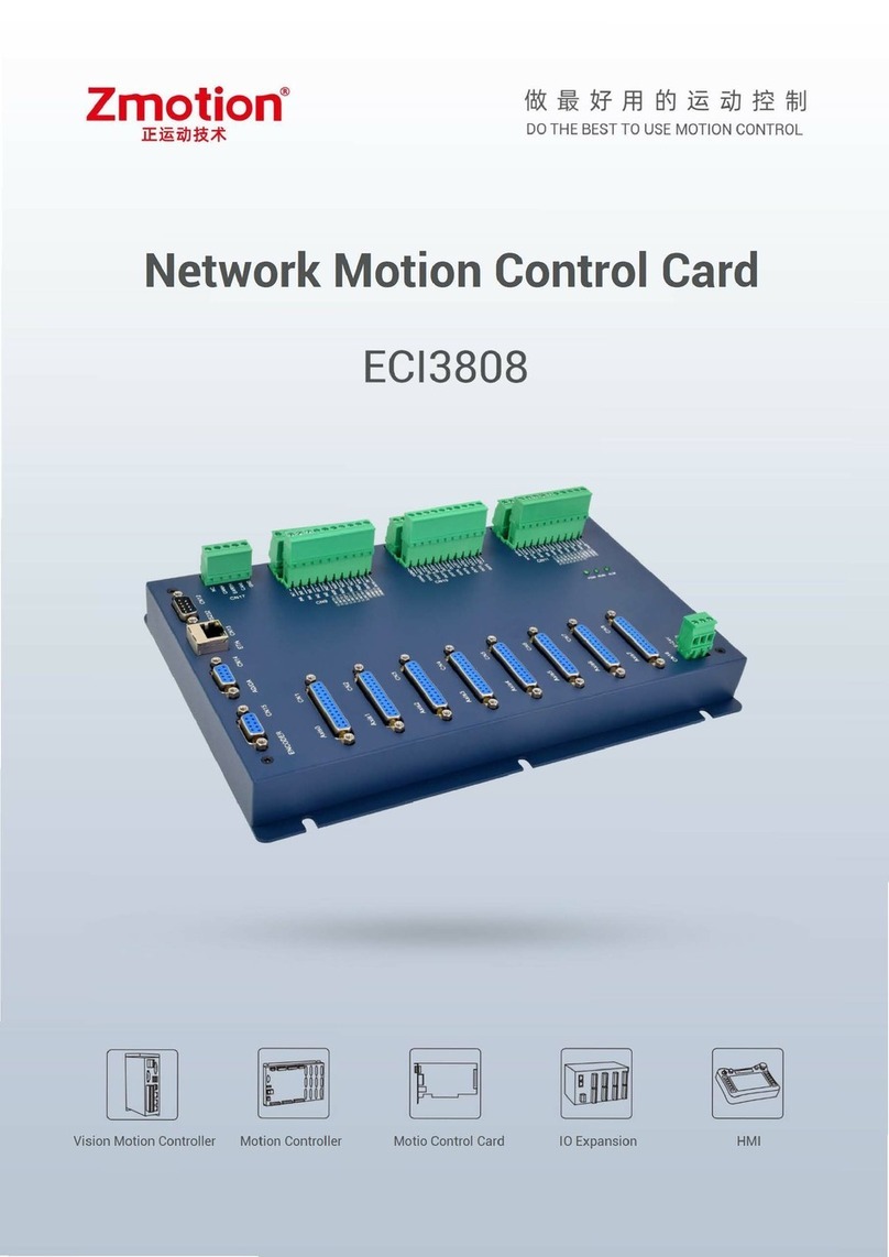
Zmotion ECI2618 User manual

ECI2610 Network Motion Control Card Hardware Manual Version1.1
1
ECI2618 Network Motion Control
Card Hardware Manual
Version 1.1

ECI2610 Network Motion Control Card Hardware Manual Version1.1
2
Copyright statement
This manual is copyrighted by Shenzhen Technology Co., Ltd.,
without the written permission of the Zmotion Technology, no person
shall reproduce, translate and copy any content in this manual.
ZMC controller software involved in details as well as the
introduction and routines of each instruction, please refer to ZBASIC
software manual.
Information contained in this manual is only for reference. Due to
improvements in design and functions and other aspects, Zmotion
Technology reserves the final interpretation! Subject to change without
notice!
Pay attention to safety when debug the machine! Be sure to
design effective safety devices in the machine, and add the error
handling procedures in software. Zmotion has no obligation or
responsibility for the loss.

ECI2610 Network Motion Control Card Hardware Manual Version1.1
3
Content
ECI2618 Network Motion Control Card Hardware Manual.............................................................1
Chapter I Control Card Introduction.................................................................................................5
1.1 Connection Configuration...................................................................................................5
1.2 Installation and Programming.............................................................................................6
1.3 Features...............................................................................................................................7
Chapter II Hardware Description......................................................................................................8
2.1 ECI1A00 Series Controller .................................................................................................8
2.1.1 Order Information ....................................................................................................9
2.2 ECI2610 Wiring Reference...............................................................................................10
2.2.1 Power / CAN Interface...........................................................................................11
2.2.2 RS232 Interface......................................................................................................11
2.2.3 Ethernet Interface Signal........................................................................................12
2.2.4 Analog input and output signal...............................................................................12
2.2.5 General Input signal ...............................................................................................12
2.2.6 Input 0-7.................................................................................................................13
2.2.6 Input 8-15...............................................................................................................13
2.2.6 Input 16-23.............................................................................................................14
2.2.9 Output 0-7 ..............................................................................................................14
2.2.10 Output 8-15 ..........................................................................................................15
2.2.11 Handwheel Interface Signal .................................................................................16
2.2.12 Axis Interface Signal............................................................................................18
2.2.13 Axis Wiring Reference .................................................................................................20
2.2.13.1 Wiring Reference for Low-speed Differential Pulse and Encoder Axis............20
2.2.13.2 Wiring reference for High-speed Differential Pulse or Encoder Axis.......22
2.2.13.3 Wiring Reference for Encoder Axis ..........................................................24
Chapter III Expansion Module........................................................................................................25
3.1 Wiring Reference For CAN, Input, Output and Power .....................................................25
Chapter IV Common Problems.......................................................................................................26

ECI2610 Network Motion Control Card Hardware Manual Version1.1
4
Chapter V Hardware Installation.....................................................................................................28
5.1 ECI2610 Installation .........................................................................................................28

ECI2610 Network Motion Control Card Hardware Manual Version1.1
5
Chapter I Control Card Introduction
⚫ECI is the abbreviation of network motion control card published by ZMOTION
Technology.
⚫ECI2610 Series control card supports linear interpolation up to 12 axes, and
interpolation of random circular, spherical, helical, electronic cam, electronic gear,
synchronous follow, virtual axis, robot structure, etc. Real-time motion control can
be achieved through optimized network communication protocol.
1.1 Connection Configuration
ECI network motion control card supports Ethernet and 232 communication
interfaces connect with computer, and receive instructions from computer. Also, it links
with each expansion module through ZCAN bus to extend inputs, outputs and axes of
motion (a 120Ω resistance is needed between CANL and CANH).

ECI2610 Network Motion Control Card Hardware Manual Version1.1
6
1.2 Installation and Programming
ZDevelop Development Environment
ECI motion control card is programmed and debugged by ZDevelop software.
ZDevelop, the software is easy to program, compile and debug. Link ZDevelop and
controller through serial port or Ethernet.
Application procedures can be programmed by VC, VB, VS, C ++ Builder, C #
and other software development. When debugs, Zevelop software can be connected
with controller simultaneously, but needs a dynamic library when the procedure is
running: zmotion.dll.

ECI2610 Network Motion Control Card Hardware Manual Version1.1
7
1.3 Features
⚫Motion control of up to 12 axes.
⚫Pulse output mode: Direction / pulse or double mode.
⚫Encoder position measurement is supported and can be configured as hand wheel
input mode.
⚫Specialized handwheel input interface.
⚫Maximum frequency output of each axis: 10MHz.
⚫Maximum inputs or outputs can reach 512 through CAN.
⚫The positive or negative limit signal / origin signal of axis can be configured to any
inputs.
⚫The output current can reach 300mA, which can directly drive some kinds of
solenoid valves.
⚫Interface: RS232, Ethernet.
⚫Linear interpolation of up to 12 axes, interpolation of random, spherical and helical.
⚫Electronic cam, electronic gear, position latch, synchronous follow and virtual axis
etc.
⚫Multi-file and multi-task programming in ZBasic.
⚫A variety of program encryption methods to protect the intellectual property rights
of customers.

ECI2610 Network Motion Control Card Hardware Manual Version1.1
8
Chapter II Hardware Description
2.1 ECI2618 Series Controller
ECI2618
Axes
6
Max extended axes
12
Basic axis type
Pulse / encoder
Internal IO
24 inputs and 16 outputs (with overcurrent protection),
each axis has another 2 inputs and 1 output (output in the
axis only can do enable)
Max extended IO
Up to 256 inputs and 256 outputs
Max extended AD/DA
128 ADs, 64DAs
Pulse bit
32
Encoder bit
32
Speed/acceleration bit
32
Max pulse frequency
10Mhz
Axis motion buffer
128
Array space
1600
Procedure space
4Kbyte
Flash space
128KByte
Power input
24V DC input (since consumption is within 10W, fan
cooling is not needed), IO consumption is not included.
Communication
RS232, Ethernet, CAN
Size
220*139mm

ECI2610 Network Motion Control Card Hardware Manual Version1.1
9
2.1.1 Order Information
Model
Specification
ECI2610
6 axes, point to point, electronic cam, doesn’t support interpolation
ECI2612
6 axes, point to point, electronic cam, linear interpolation
ECI2616
6 axes, point to point, electronic cam, linear interpolation, circular
interpolation
ECI2618
6 axes, point to point, electronic cam, linear interpolation, circular
interpolation, continuous interpolation, robotic arm structure

ECI2610 Network Motion Control Card Hardware Manual Version1.1
10
2.2 ECI2610 Wiring Reference
➢ECI2610 has most 6 axes, each axis has independent encoder, virtual axis can reach
12 axes through expansion module. Axis 4 is relative to encoder axis 10, which is
allocated as handwheel axis number by default.
➢ECI2610 has 24 general inputs and 16 general outputs, 2 ADs and 2 DAs.
➢ECI2610 has one RS232 serial port and one Ethernet interface.
➢ECI2610 has one CAN bus interface, which supports connect with expansion
module and motion controller through ZCAN protocol.
➢ECI2610 has one handwheel interface.

ECI2610 Network Motion Control Card Hardware Manual Version1.1
11
2.2.1 Power / CAN Interface
PIN NO
Name
Description
1
GND
Internal power ground
2
CANL
CAN differential data -
3
EARTH/SHIELD
Shield
4
CANH
CAN differential data +
5
+24V
Internal power 24V input
For communication quality, please use twisted pair shielded wire, and shield
connects with the ground, the internal power of controller and expansion module use
the same one.
When multi controllers are linked on CAN bus, it is necessary to connect 120 Ω
resistor between CANL and CANH of the last IO expansion module.
2.2.2 RS232 Interface
PIN NO
Name
Description
2
RXD
Receive data PIN
3
TXD
Send data PIN
5
GND
Internal power ground
9
DC5V
Power 5V output, it supplies text screen.
Crossover cable with two female head is needed when try to link to computer.

ECI2610 Network Motion Control Card Hardware Manual Version1.1
12
2.2.3 Ethernet Interface Signal
It supports one group 100M Ethernet communication. When the green lights
constantly, means there connects and works under full duplex modes. When the
yellow light blinks, means it is communicating now.
2.2.4 Analog input and output signal
PIN
Name
Description
1
DA0
0-10V analog output 0
2
DA1
0-10V analog output 1
3
ADGND
Analog GND
4
AD0
0-10V analog input 0
5
AD1
0-10V analog input 1
ECI2610 analog ADDA uses internal power.
2.2.5 General Input signal

ECI2610 Network Motion Control Card Hardware Manual Version1.1
13
2.2.6 Input 0-7
PIN
Name
Description
1
EGND
External power ground (not connect with switch power)
2
EGND
External power ground (not connect with switch power)
3
IN0
Input 0 (latch A)
4
IN1
Input 1 (latch B)
5
IN2
Input 2
6
IN3
Input 3
7
IN4
Input 4
8
IN5
Input 5
9
IN6
Input 6
10
IN7
Input 7
Input 0 and input 1 have latch input A and latch input B function synchronously,
input signals are N type low electricity level valid input.
2.2.7 Input 8-15
PIN
Name
Description
1
EGND
External power ground (not connect with switch power)
2
EGND
External power ground (not connect with switch power)
3
IN8
Input 8
4
IN9
Input 9
5
IN10
Input 10
6
IN11
Input 11
7
IN12
Input 12
8
IN13
Input 13
9
IN14
Input 14
10
IN15
Input 15

ECI2610 Network Motion Control Card Hardware Manual Version1.1
14
2.2.8 Input 16-23
PIN
Name
Description
1
EGND
External power ground (not connect with switch power)
2
EGND
External power ground (not connect with switch power)
3
IN16
Input 16
4
IN17
Input 17
5
IN18
Input 18
6
IN19
Input 19
7
IN20
Input 20
8
IN21
Input 21
9
IN22
Input 22
10
IN23
Input 23
2.2.9 Output 0-7
PIN
Name
Description
1
OUT7
Output 7
2
OUT6
Output 6
3
OUT5
Output 5
4
OUT4
Output 4

ECI2610 Network Motion Control Card Hardware Manual Version1.1
15
5
OUT3
Output 3
6
OUT2
Output 2
7
OUT1
Output 1, PWM1
8
OUT0
Output 0, PWM0
9
EGND
External power ground (not connect with switch power)
10
EGND
External power ground (not connect with switch power)
OUT0 and OUT1 have PWM function, they are general output when PWM is
shut down.
2.2.10 Output 8-15
PIN
Name
Description
1
OUT15
Output 15
2
OUT14
Output 14
3
OUT13
Output 13
4
OUT12
Output 12
5
OUT11
Output 11
6
OUT10
Output 10
7
OUT9
Output 9
8
OUT8
Output 8
9
E5V
5V power generated from 5V, output
10
EGND
External power ground (not connect with switch power)
EGND in input and output terminals are external power ground, they can not be
connected to switch power.

ECI2610 Network Motion Control Card Hardware Manual Version1.1
16
2.2.11 Handwheel Interface Signal
PIN
Name
Description
1
H-5V
Supply power for handwheel
2
HA-
Encoder A phase signal (IN36)
3
HB-
Encoder B phase signal (IN37)
4
HEMGN
Emergency stop signal (IN47)
5
NC
6
HX1
Select X1 ration (IN38)
7
HX10
Select X10 ration (IN38)
8
HX100
Select X100 ration (IN38)
9
HSU
Select axis 3 (IN44)
10
NC
11
EGND
External power ground
12
NC
13
HSZ
Select axis 2 (IN43)
14
HSY
Select axis 1 (IN42)
15
HSX
Select axis 0 (IN41)

ECI2610 Network Motion Control Card Hardware Manual Version1.1
17
Handwheel wiring circuit
IN36-IN37 in the handwheel terminal only support 5V electricity level input,
which can not be used as 24V general input. The products with hardware ID number
1909***** support 5-24V electricity level input, means it can be used as 24V standard
general input.

ECI2610 Network Motion Control Card Hardware Manual Version1.1
18
2.2.12 Axis Interface Signal
◆Each terminal provides 0V and + 5V output, which also can provide 5V power for
the encoder.
◆Do set its parameterATYPE before use axis.
Alarm input, on-position signal and axis enable output can be used as general
input and output simultaneously.
Each axis has independent encoder except axis 4. Axis 4 is relative to encoder
axis 10, which is allocated as handwheel axis number by default.
PIN
Signal
Description
1
EGND
External power ground
2
IN24-29/ALM
General input, recommended to do drive alarm
3
OUT16-
21/ENABLE
General output, recommended to do drive enable
4
EA+
Encoder input
5
EB+
Encoder input
6
EZ+
Encoder input
7
+5V
Power input
8
Reserved
Reserved
9
DIR+
Servo/stepper directional output
10
GND
Digital ground
11
PUL-
Servo/stepper pulse output

ECI2610 Network Motion Control Card Hardware Manual Version1.1
19
12
Reserved
Reserved
13
GND
Digital ground
14
OVCC
+24V output (recommended for servo IO only)
15
Reserved
Reserved
16
IN30-35/INPOS
General input, recommended to do on-position signal
17
EA+
Encoder input
18
EB+
Encoder input
19
EZ+
Encoder input
20
GND
Digital ground
21
GND
Digital ground
22
DIR-
Servo/stepper directional output
23
PUL+
Servo/stepper pulse output
24
GND
Digital ground
25
Reserved
Reserved
26
Reserved
Reserved

ECI2610 Network Motion Control Card Hardware Manual Version1.1
20
2.2.13 Axis Wiring Reference
2.2.13.1 Wiring Reference for Low-speed Differential Pulse
and Encoder Axis
Differential Connection
Single-ended Connection
Table of contents
Other Zmotion Network Hardware manuals
Popular Network Hardware manuals by other brands

MTL
MTL 9468-ET instruction manual

AMX
AMX NXA-AVB/RGB quick start guide

Northern Telecom
Northern Telecom Meridian 1 PC Console Interface Unit installation guide

Emulex
Emulex LP21000 Deployment guide

Orolia
Orolia SecureSync 1200 Getting started guide

Radyne ComStream
Radyne ComStream DM240-DVB Installation and operation manual

Advantech
Advantech B+B SMARTWORX UH401 Series quick start guide

XTS
XTS Network Video Recorder user manual

Moxa Technologies
Moxa Technologies AirWorks AWK-1137C user manual

Clavister
Clavister SG4500 Series Getting started guide

Cabletron Systems
Cabletron Systems MMAC-Plus 9A128-01 Management guide

Vista
Vista Viper quick start guide