2
© Copyright 2021 Zoeller®Co. All rights reserved.
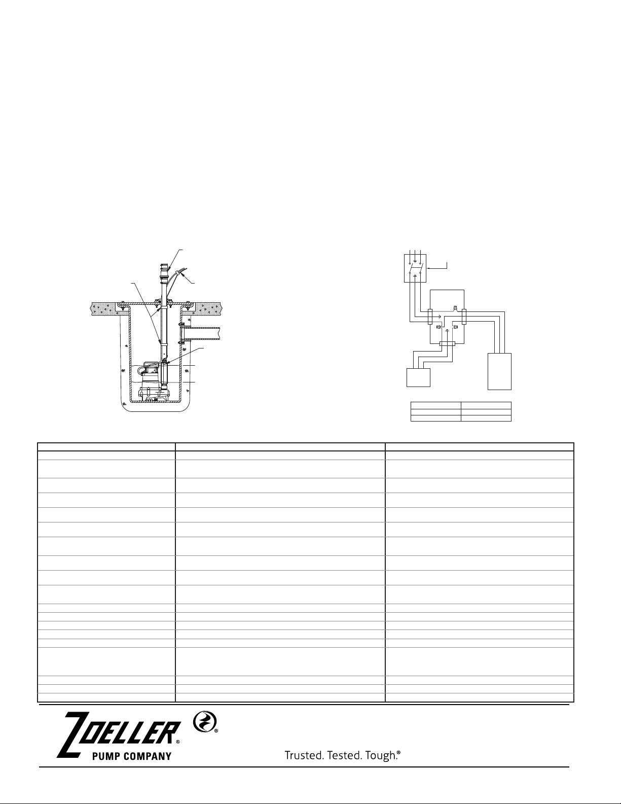
FIGURE 3
MAIL TO: P.O. BOX 16347 • Louisville, KY 40256-0347 USA
SHIP TO: 3649 Cane Run Road • Louisville, KY 40211-1961 USA
+1 (502) 778-2731 • 1-800-928-7867 • FAX +1 (502) 774-3624 visit our web site:
zoellerpumps.com
MODEL NO. SUMP SEWAGE
X
10-4660 X
53-0084 X
98-0069 X
267-0121 X
SWITCH TYPE POWER WIRE COLOR
SUMP RED
SEWAGE BLUE
DISCHARGE PIPE
CORDS SECURED TO
LEVEL
PUMP "OFF"
LEVEL
PUMP "ON"
ZOELLER UNICHECK
TO POWER SUPPLY
REDUNDANT "ON"
LEVEL
MOUNT FLOATLESS SWITCH
WITH (2) TIE STRAPS THAT
ARE PROVIDED WITH SWITCH.
PUMP PLUG
SWITCH PLUG
AUTOMATIC
OPERATION MANUAL
OPERATION
L1L2
SWITCH
DISCONNECT
WATERTIGHT
JUNCTION BOX
WHITE
BLACK
SEE CHART
BLACK
WHITE
WHITE
GREEN
BLACK
PUMP
FLOATLESS
SWITCH
SK3180
SYMPTOM POSSIBLE ROOT CAUSE POTENTIAL CORRECTIVE ACTION
A. Pump will not start or run.
Switch cord improperly plugged into receptacle Properly insert plug into receptacle
Pump cord improperly plugged into pump switch plug Properly insert pump cord into pump switch piggyback
plug
Blown panel fuse or breaker Replace with proper sized fuse or reset breaker
GFCI receptacle tripped Reset GFCI receptacle
Low voltage If voltage under 108 volts, contact qualied electrician
Main power outage The pump switch will not work without power
Contamination built-up on pump switch exterior See " Switch Maintenance" for proper cleaning
instructions
Improper mounting/ loose See "Installation Instructions"
Damaged or defective pump switch Contact Zoeller Product Support
B. Pump starts and stops too
often.
Signicant in-ow of water This is normal. Check pump specication to conrm
adequate pumping capacity
Pump switch mounted facing inlet pipe Reinstall switch facing away from inlet pipe
Defective check valve Replace the check valve
Excessive temperature Let system cool down for 5 minutes
Improper mounting/ loose See "Installation Instructions"
Damaged or defective pump switch Contact Zoeller Product Support
C.
Pump will not shut off when
water is not present at the
lower limit.
Contamination built-up on pump switch exterior See "Switch Maintenance" for proper cleaning
instructions
Improper mounting/ loose See "Installation Instructions"
Foreign conductive object near sensor Remove foreign object
Damaged or defective pump switch Contact Zoeller Product Support
TROUBLESHOOTING FOR FLOATLESS WATER LEVEL SWITCH
OPERATION:
1. Allow the sump to ll until the water level reaches the ON point.
2. Sump pump will turn on within 3 seconds of the water level reaching the ON point.
3. The pump will remain on until the water level drops below the OFF point. The pump may remain on up to 1 second after passing the
OFF point.
4. This will set the standard run time for the switch.
5. If the pump runs for longer than the standard run time, the standard run time will be incremented by 5 seconds on future cycles. This
will repeat until the run time is long enough for the water to reach the off level or the run time is increased to two minutes.
6. If water is over the "ON" level the pump will run continuously until the water is below the "ON" level, at which point the switch will revert
to standard operation.
MODEL NO. SUMP SEWAGE
X
10-4660 X
53-0084 X
98-0069 X
267-0121 X
SWITCH TYPE POWER WIRE COLOR
SUMP RED
SEWAGE BLUE
DISCHARGE PIPE
CORDS SECURED TO
LEVEL
PUMP "OFF"
LEVEL
PUMP "ON"
ZOELLER UNICHECK
TO POWER SUPPLY
REDUNDANT "ON"
LEVEL
MOUNT FLOATLESS SWITCH
WITH (2) TIE STRAPS THAT
ARE PROVIDED WITH SWITCH.
PUMP PLUG
SWITCH PLUG
AUTOMATIC
OPERATION MANUAL
OPERATION
L1L2
SWITCH
DISCONNECT
WATERTIGHT
JUNCTION BOX
WHITE
BLACK
SEE CHART
BLACK
WHITE
WHITE
GREEN
BLACK
PUMP
FLOATLESS
SWITCH
FIGURE 4
For direct wire installations only
FLOATLESS SWITCH MAINTENANCE
Warning: Unplug Floatless switch and pump from all electrical power
BEFORE doing any service or maintenance.
• Inspect area around pump switch, wipe free of buildup and clear all
foreign objects.
• Plug pump switch and pump back into receptacle after inspection.
Check for proper operation.
• We recommend that you do this maintenance at least once a year.
However, harsh environmental conditions may dictate the frequency
of your actual maintenance schedule.
• Floatless pump switch contains NO serviceable parts.
Do not disassemble pump switch. Doing so can result
in death or electrical shock and voided warranty.
• If pump switch stops working, refer to
troubleshooting instructions provided.
• If part is under warranty, contact factory or sale
location.
• If part is not under warranty, the lawful disposal of
unit is necessary.


