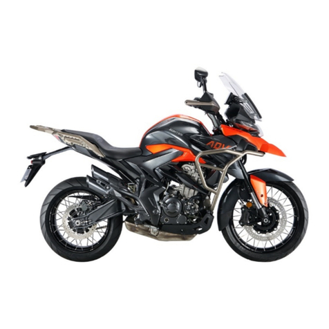
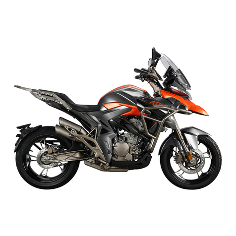
Zontes ZT350-GK 2022 User manual

ZT350-GK
Service manual
2022/02/16

Pages
0
Table of Contents……………………………………………………………………………………………………………………………………………………………………………………………………
1
1FRAME&ELECTRONIC COMPONENT
1.1
Electronic parts component 2…………………………………………………………………………………………………………………………………………………………………………………………
8
Remove the dump switch/ECU
1.2
Electronic parts component 2…………………………………………………………………………………………………………………………………………………………………………………………
9
Horn/Shut down switch/Ignition coil
1.3
Frame plastic parts……………………………………………………………………………………………………………………………………………………………………………………………………
10
Remove the Fuel tank liner limit glue/Battery cushion/Side cover cushion/Buckle
1.4
Directional column component………………………………………………………………………………………………………………………………………………………………………………………
11
Dissembly/Assemble
1.5
Frame, Side support, the operation of releasing engine oil…………………………………………………………………………………………………………………………………………………………
12
Remove realease the oil cooler enging oil/oil cooler/sider support;Checking the steel bowl
2FRAME & ENGINE COMBINATION
2.1
Engine component …………………………………………………………………………………………………………………………………………………………………………………………………
13
Remove the engine/Engine left rear cover
3INTAKE SYSTEM COMPONENT
3.1
Carbon tank component ……………………………………………………………………………………………………………………………………………………………………………………………
14
Remove the air filter intake air temperature sensor/carbon tank electromagnetic valve/carbon tank;Check whether the temperature sensor is damaged
3.2
The air filter assembly ………………………………………………………………………………………………………………………………………………………………………………………………
15
Remove the air filter/throttle valve component;Check whether the external intake pressure sensor is damaged/whether the fuel injector is damaged
3.3
Throttle valve body component………………………………………………………………………………………………………………………………………………………………………………………
16
Remove the throttle valve body component/external intake air pressure sensor/check whether the stepping motor is damaged /check whether the throttle position sensor 500ccw is damaged
3.4
Replace air filter element……………………………………………………………………………………………………………………………………………………………………………………………
17
Remove the filter element;Clean the Oil pipe and water pipe
4REAR WHELL COMPONENT
4.1
Rear mud board………………………………………………………………………………………………………………………………………………………………………………………………………
18
4.2
Rear shock absorption………………………………………………………………………………………………………………………………………………………………………………………………
19
Remove the rear shock absorber/adjust the rear absorber/check/troubleshooting
4.3
Rear wheel component 1……………………………………………………………………………………………………………………………………………………………………………………………
20
Contents
Table of Contents
Page 1 ,Toatal 93 Pages

Pages
Contents
Table of Contents
Remove the rear wheel component
4.4
Rear wheel component 2……………………………………………………………………………………………………………………………………………………………………………………………
21
Remove the sprocket seat component/fault detection of sprocket seat
4.5
Rear wheel component 3……………………………………………………………………………………………………………………………………………………………………………………………
22
Remove the disc brake plate&ABS gear ring/tire and wheel component
4.6
Rear fork component…………………………………………………………………………………………………………………………………………………………………………………………………
23
Remove the rear fork component/rear fork rear-resistant block
4.7
Replace the rear brake pads…………………………………………………………………………………………………………………………………………………………………………………………
24
Disassemble disc brake arrester/change rear disc brake arrester
4.8
Rear brake main pump adds brake fluid……………………………………………………………………………………………………………………………………………………………………………
25
5PEDAL COMPONENT
5.1
Shift lever adjustment………………………………………………………………………………………………………………………………………………………………………………………………
26
Adjust the height of gear shift rod/shift lever position adjustment
5.2
Right footrest component 1…………………………………………………………………………………………………………………………………………………………………………………………
27
5.3
Right footrest component 2…………………………………………………………………………………………………………………………………………………………………………………………
28
Remove the rear brake main pump heat shield/rear disc brake main pump component
5.4
Right footrest component 3…………………………………………………………………………………………………………………………………………………………………………………………
29
Remove the brake pedal component/muffler anti-scalding
5.5
Right footrest component 4…………………………………………………………………………………………………………………………………………………………………………………………
30
Remove the R, front pedal/R,rear pedal/after sales parts for pedal component
5.6
Left footrest component 1……………………………………………………………………………………………………………………………………………………………………………………………
31
Remove the L, foot pedal holder component/gear shift rod component/rectifier/support of disc brake lock;Rectifier fault detection
5.7
Left footrest component 2……………………………………………………………………………………………………………………………………………………………………………………………
32
Remove the gear shift rod component
5.8
Left footrest component 3……………………………………………………………………………………………………………………………………………………………………………………………
33
Remove the rear left pedal/L, rear foot pedal/after sales parts for pedal component
6COOLING SYSTEM COMPONENT
6.1
Change engine oil……………………………………………………………………………………………………………………………………………………………………………………………………
34
Drain oil/change engine oil
6.2
Change engine oil filter………………………………………………………………………………………………………………………………………………………………………………………………
35
6.3
Add coolant …………………………………………………………………………………………………………………………………………………………………………………………………………
36
6.4
Water tank decorative cover component 1……………………………………………………………………………………………………………………………………………………………………………
37
Page 2 ,Toatal 93 Pages

Pages
Contents
Table of Contents
Remove the right water tank trim cover component/left water tank trim cover component
6.5
Water tank decorative cover rcomponent 2…………………………………………………………………………………………………………………………………………………………………………
38
Remove the bottom plate of right decorative cover of water tank/bottom plate of left decorative cover of water tank
6.6
Water tank decorative cover component 3……………………………………………………………………………………………………………………………………………………………………………
39
Remove the middle trim panel of water tank
6.7
Auxiliary water tank component……………………………………………………………………………………………………………………………………………………………………………………
40
Remove the auxiliary water tank/auxiliary water tank support
6.8
Draining cooling liquid………………………………………………………………………………………………………………………………………………………………………………………………
41
6.9
Main water tank component 1………………………………………………………………………………………………………………………………………………………………………………………
42
6.10
Main water tank component 2………………………………………………………………………………………………………………………………………………………………………………………
43
6.11
Water tank bracket……………………………………………………………………………………………………………………………………………………………………………………………………
44
6.12
Oil cooler component 1………………………………………………………………………………………………………………………………………………………………………………………………
45
6.13
Oil cooler component 2………………………………………………………………………………………………………………………………………………………………………………………………
46
Remove the oil cooler bracket
77-FRONT FORK COMPONENT
7.1
Throttle/clutch cable clearance adjustmen……………………………………………………………………………………………………………………………………………………………………………
47
Adjust the free travel of throttle wire and clutch zipper
7.2
Light height adjustment,replacement clutch cable……………………………………………………………………………………………………………………………………………………………………
48
7.3
Replace the throttle cable……………………………………………………………………………………………………………………………………………………………………………………………
49
Remove the throttle cable/install the throttle cable/right handlebar switch
7.4
Steering adjustment…………………………………………………………………………………………………………………………………………………………………………………………………
50
Check steering device
7.5
Right hand component………………………………………………………………………………………………………………………………………………………………………………………………
51
Remove the right rearview mirror/hand guard/generation right hand switch
7.6
Add brake fluid, rocker adjustment…………………………………………………………………………………………………………………………………………………………………………………
52
7.7
Replace the front brake pads…………………………………………………………………………………………………………………………………………………………………………………………
53
7.8
Front wheel component………………………………………………………………………………………………………………………………………………………………………………………………
54
Remove the tire and wheel component/brake disc, ABS ring gear/tire and wheel component
7.9
Front mud board & wheel speed sensor component…………………………………………………………………………………………………………………………………………………………………
55
Remove the wheel speed sensor/front disc brake caliper/front mud board component
7.10
Front mud board & Front disc brake disc pritective cover component ……………………………………………………………………………………………………………………………………………
56
Remove the front disc brake guard component/decompose front mud board component
7.11
Head and headlights component 1……………………………………………………………………………………………………………………………………………………………………………………
57
Page 3 ,Toatal 93 Pages

Pages
Contents
Table of Contents
Disassemble speedometer component/headlight components
7.12
Head and headlights component 2……………………………………………………………………………………………………………………………………………………………………………………
58
Remove the eadlight bracket/eadlamp and headlamp bracket
7.13
Head and headlights component 3……………………………………………………………………………………………………………………………………………………………………………………
59
Remove the left and right head cover components and headlamp mask
7.14
Head and headlights component 4……………………………………………………………………………………………………………………………………………………………………………………
60
Remove the left and right turn signal components/speedometer component
7.15
Head and headlights component 5……………………………………………………………………………………………………………………………………………………………………………………
61
Remove the headlamp bracket/junction box component/USB charging cable
7.16
Left hand component…………………………………………………………………………………………………………………………………………………………………………………………………
62
Remove the left mirror,left switch,hand guard/left handlebar rubber sleeve/replace the left-hand handle rocker arm and clutch switch
7.17
Directional lever component…………………………………………………………………………………………………………………………………………………………………………………………
63
7.18
Front shock absorber, upper plate component………………………………………………………………………………………………………………………………………………………………………
64
Remove the uplink board component/front left and right shock absorption/reflector/faucet lock
7.19
Uplink plate, direction handle block component……………………………………………………………………………………………………………………………………………………………………
65
7.20
ABS brake system-A 1………………………………………………………………………………………………………………………………………………………………………………………………
66
Remove the hydraulic control unit component
7.21
ABS brake system-A 2………………………………………………………………………………………………………………………………………………………………………………………………
67
Release brake fluid/remove FMC-HU
7.22
ABS brake system-A 3………………………………………………………………………………………………………………………………………………………………………………………………
68
Release brake fluid/remove the front disc crake caliper and oil pipe
7.23
ABS brake system-A 4………………………………………………………………………………………………………………………………………………………………………………………………
69
RMC-HU/wheel speed sensor/rear disc brake caliper/RC-HU
88-SURROUNDING COMPONENT
8.1
Fuel tank component…………………………………………………………………………………………………………………………………………………………………………………………………
70
8.2
Fuel Tank middle cover component…………………………………………………………………………………………………………………………………………………………………………………
71
Remove the fuel tank middle cover component/fuel tank lock/fuel tank cover compnent
8.3
Oil tank outer cover component………………………………………………………………………………………………………………………………………………………………………………………
72
Remove the fuel tank cover/swivel bracket
8.4
Oil pump……………………………………………………………………………………………………………………………………………………………………………………………………………
73
Remove the oil pump component/shroud glass strip/fuel tank cap/heat insulation cotton
99-FUEL TANK COMPONENT
Page 4 ,Toatal 93 Pages

Pages
Contents
Table of Contents
9.1
Side cover component 1………………………………………………………………………………………………………………………………………………………………………………………………
74
9.2
Side cover component 2………………………………………………………………………………………………………………………………………………………………………………………………
75
Remove the charging port base
9.3
Side cover component 3………………………………………………………………………………………………………………………………………………………………………………………………
76
9.4
Side cover component 4………………………………………………………………………………………………………………………………………………………………………………………………
77
10 GUARD BAR COMPONENT
10.1
Guard bar component 1………………………………………………………………………………………………………………………………………………………………………………………………
78
Guard bar
10.2
Guard bar component 2………………………………………………………………………………………………………………………………………………………………………………………………
79
Left guard bar/Right guard bar
11 Rear cover component
11.1
Electric device box cover component ………………………………………………………………………………………………………………………………………………………………………………
80
Remove electric device box cover component
11.2
Colloid battery………………………………………………………………………………………………………………………………………………………………………………………………………
81
Remove battery,relay and lasher
11.3
Rear armrest component……………………………………………………………………………………………………………………………………………………………………………………………
82
Remove rear armrest/taillight holder/OBD diagnosis interface position/buzzer
11.4
PKE…………………………………………………………………………………………………………………………………………………………………………………………………………………
83
Remove PKE/antenna
11.5
Electric device box component 1……………………………………………………………………………………………………………………………………………………………………………………
84
Remove electric device box component
11.6
Electric device box component 2……………………………………………………………………………………………………………………………………………………………………………………
85
Remover battery bracket
11.7
Rear mud board component 1………………………………………………………………………………………………………………………………………………………………………………………
86
Remover cushion lock/rear mud board component/taillight
11.8
Rear mud board component 2………………………………………………………………………………………………………………………………………………………………………………………
87
Decompose rear mud board/license plate light/turn singal light
12 CUSHION COMPONENT
12.1
Cushion………………………………………………………………………………………………………………………………………………………………………………………………………………
88
Discomponent and component cushion; seat cushion rubber separately purchased parts
Page 5 ,Toatal 93 Pages

Pages
Contents
Table of Contents
13 Muffler component
13.1
Muffler component 1…………………………………………………………………………………………………………………………………………………………………………………………………
89
Remove the rear section of the muffler
13.2
Muffler component 2…………………………………………………………………………………………………………………………………………………………………………………………………
90
Decompose the rear section of the muffle,muffler component mounting points on both sides
13.3
Muffler component 3…………………………………………………………………………………………………………………………………………………………………………………………………
91
Decompose the front section of the muffler
14 Lower shroud component
14.1
Lower shroud component 1…………………………………………………………………………………………………………………………………………………………………………………………
92
Remove the shroud component, shroud bracket
14.2
Lower shroud component 2…………………………………………………………………………………………………………………………………………………………………………………………
93
Decompose the lower shroud component
Page 6 ,Toatal 93 Pages

Pages
Contents
Table of Contents
©Guangdong Tayo Motorcycle Technolog Co.
Ltd All rights reserve
All the information, illustrations and photographs collected in this manual are compiled according to the latest products. However, there may be some inconsistencies between your motorcycle and this
manual due to the continuous improvement of the product and other changes.
Page 7 ,Toatal 93 Pages

1-FRAME&ELECTRONIC COMPONENT 8
CHK
ADJ
NO. PART NO. PART NAME QTY CAUTION
1 1184300-027000 ZT350-GK Harness components-A 1
2 1244200-139000 ZT310 Rubber buckle(120mm) 2
3 1251100-101000 Non-standard bolt M6×12(304 stainless steel)4
4 1224200-205000 ZT310 electronic cushion lock guide block 1
5 1244100-082000 ZT250-S Dump switch rabber 1
6 1184100-002000 ZT250-S Dump switch 1
7 1250104-006097 GB16674M6×12 (chromed/HH) 2
8 1050958-014000 MSE6.0 controller-ZT184MP (Euro 5) 1Bosch EFI
9 1274100-058000 ZT310 Seat lock 1
10 1224100-030000 Pin tie (Black 4.8×130)2
11 1274300-034000 ZT350-GK dump switch support 1
PROCEDURE:
●Dump switch
Remove the rubber sleeve⑸ that connects to the mounting bracket on the frame, and remove the dump switch
⑹.
●ECU
Locate and losen the rubber buckle⑵ and Pin tie⑽.
Take off the ECU plug,After pressing the anti release buckle,rotate the ECU cable plug clockwise and pull it
out.
Remove the bolt⑺ on the frame with a 8# sleeve, and then remove the ECU⑻ .
CAUTION:
●It must be dismantled them first, such as the cushion, fuel tank component,sider cover, tail dress and so on.
●In order to avoid the improper contact of the bending electrical parts, please pay attention to the direction and
angle of force when plugging the electrical parts, so as to avoid the improper contact of the bending electrical
parts. No violent operation.
●Please notice the limit of the bracket when dismantling dump switch sleeve, beware of hurting your fingers.
Fig.1FRAME&ELECTRO
NIC COMPONENT Electronic parts COMPONENT 1

1-FRAME&ELECTRONIC COMPONENT 9
CHK
ADJ
NO. PART NO. PART NAME QTY CAUTION
1 1251100-101000 Non-standard bolt M6×12 (304 stainless steel) 1
2 1184200-004000 ZT310 Horn 1
4 1274100-017000 ZT250
-
S Cable clip 2
5 1244200-139000 ZT310 rubber buckle (120mm) 1
6 1274100-095000 ZT250
-
S Holder of flameout switch cable 1
7 1184100-012000 ZT250
-
S Flameout switch 1
8 1250205-040095 GB70.1 inner hex bolt M8×16
(
color Zinc
)
2
9 1050958-006000 ZT350 Ignition coil 1
10 1050958-007000 ZT350 EFI high voltage line 1
11 1251100-061093 M6×22 Hex flang bolt thread level 8.8 (color zinc) 2
12 1224100-037000 0 level antiflaming binding
(
black 3.6×295
)
1
Fig.2FRAME&ELECTRO
NIC COMPONENT Electronic parts COMPONENT 2
3 4024300-023051 ZT350-GK Water tank upper bracket (dark gray
matte) 1
PROCEDURE:
●Horn
Take off the plug of horn, hold the horn⑵ by one hand use 8# sleeve remove bolts ⑴ by another hand,then take
off the horn⑵.
●Shut down switch
Find and take off the plug of the shut down switch⑺;press the Cable clip⑷ inward in the reverse direction of
the arrow in the figure and pull it out;Cut the tie⑿.Using 6# inner hexagon socket remove 2pcs bolts⑻ then take
off shut down switch⑺ and bracket⑹.
●Ignition coil
Find and remove the ignition coil⑼.Take off the rubber buckle⑸
, plug,pull out the EFI high voltage line in the
direction indicated by the arrow "a" "b" ,remove the EFI high voltage line⑽; after holding the ignition coil then
using 8#sleeve remove bolts ⑾,remove the ignition coil⑼.
CAUTION:
●When take off the plug can't drag any cable.
●Pay attention to the force when removing the buckle to prevent damage to the buckle.

1-FRAME&ELECTRONIC COMPONENT 10
CHK
ADJ
NO. PART NO. PART NAME QTY CAUTION
1 1241200-044000 KD150
-
U Inner fuel tank fix glue cushion 2
2 1240300-007000 HJ125
-
6 battery cushion 1
3 1244100-002000 ZT250
-
S side cover cushion 6
4 1244100-061000 ZT250 Frame water proof rubber plug 4
5 1274300-066000 ZT350
-
GK main cable bracket 1
6 1224300-055000 ZT350
-
GK Fuse box clip 1
7 1224300-057000 ZT350
-
GK Harness buckle seat(Frame tube) 3
8 1251100-101000 Non-standard bolt M6×12 (304 stainless steel) 1
9 1224100-037000 0 level antiflaming binding
(
black 3.6×295
)
3
PROCEDURE:
●Fuel tank liner limit glue
Push out the fuel tank liner limit glues⑴ then take off.
●Battery cushion
Put off the battery cushion ⑶directly by hand.
●Side cover cushion
Remove the side cover cushion⑵with your hand directly.
●Frame waterproof rubber plug
Remove the 6pcs frame waterproof rubber plugs ⑷with your hand directly.
●Buckle
Remove the bolt ⑻ with 4# hexagon socket ,remove main cable bracket ⑸.
Press and hold the position indicated by the arrow ① to pull out the buckle, cut the tie⑼, and take off the
harness buckle seat⑺.
Buckle up according to the position indicated by the ② arrow and open the clamp⑹.
CAUTION:
●
It must be dismantled them first, such as the cushion, fuel tank component, sider cover,water tank outer cover,
upper hanging piece,engine stail dressand so on.
●All parts should be correctly assembled.
●In order to avoid the improper contact of the bending electrical parts, please pay attention to the direction and
angle of force when plugging the electrical parts, so as to avoid the improper contact of the bending electrical
parts. No violent operation.
Fig.3FRAME&ELECTRO
NIC COMPONENT Frame plastic parts

1-FRAME&ELECTRONIC COMPONENT 11
CHK
ADJ
NO. PART NO. PART NAME QTY CAUTION
1 1134100-007000 ZT250
-
S Rating nut lock washer 1
2 1251300-046093 ZT250
-
S Steering column rating nut (color zinc) 2
3 1244100-015000 ZT250
-
S Rating nut glue cushion 1
4 1244300-014000 ZT350
-
R Steering stem dust cap (Up) 1
5 1130900-024000 ZT250
-
S shaft ring 1
6 1130900-022000 ZT250
-
S conjoined steel ball 1
7 1134300-002000 ZT350
-
R conjoined steel ball 1
9 1134300-003000 ZT350
-
R lower shaft ring 1
10 1244300-015000 ZT350
-
R steering stem dust cap(down) 1
CAUTION:
●Remove the head part component, handlebarcomponent and front shock absorber component first.
●Please pay attentin to fix the awaiting repair motorcycles during disassembly,prevent dumping by
accident.
●Please check whether the steel beads of the conjoined body have abnormal phenomena such as partial
abrasion and rust.If YES, please buy the regular accessories on ZONTES official website, if not, please
be sure to grease the old grease and repaint the lubricating grease on it.
●It must be to check whether the steel ball is available during reassembly.
●It must be reasonable to adjust the steering, too loose will cause the locomotive to brake slightly, and
the locomotive will shake slightly, too tight can lead to inflexibility, resulting in safety hazards.
●If you have the ability and the right tool, you can change the shaft ring ⑼ and the dustproof cover
⑽.During the replacement process, pay attention to the protection of the lower connected plate. After
replacement, it must be to check the parallelism of the column and the damping hole, the vertical degree
of the vertical column and the lower connected plate.
●【1】the down connected plate (selfmade/with blowout patch) component⑻, has been contains the
Steering column down dustproof cover lower shaft ring⑼and steering stem dust cap(down)⑽.
【1】
PROCEDURE:
●Dissembly
Remove the lock washer⑴.
Remove the top adjusting nut ⑵ by using a special four-jaw or hook wrench tools.
Remove the rubber pad ⑶.
With one hand to hold down the down connected plate assembly ⑻, the other hand use a special four-jaw set
or hook wrench to remove the adjusting nut⑵.
Remove the down connected plate component⑻.
Remove the upper dustproof cover⑷.
Remove the shaft ring ⑸ and the steel ball⑹.
Remove the steel ball⑺ of the down connected plate component⑻.
●Assemble
When reassembling, the conjoined steel ball should be painted lubricating grease,attention to the dosage.
The torque of rating nut which closes to upper dustproof cover is required to about 14N·m.So as to be able to
rotate out of nimbleness.
The upper adjustment nut only needs to be screwed to the bottom nut groove, and should not be too tight to
prevent the rubber pad (3) from being deformed too much.
Fig.6FRAME&ELECTRO
NIC COMPONENT
Directional column component
8 4094300-002051 ZT350-RLower connection board (dark gray
matte/including shaft ring) 1

1-FRAME&ELECTRONIC COMPONENT 12
CHK
ADJ
NO. PART NO. PART NAME QTY CAUTION
1
4014300-019000 Frame after-sales assembly(with seat / nameplate/Europe Ⅴ)
1
2 1130900-026000 ZT250
-
S upper steel bowl 1After-sale
3 1264100-001000 ZT250
-
S Side support spring 1
4 1271200-165000 ZT310
-
T side bracket (short / dark gray) 1
5 1251300-057093 Non-standard bolt M10×1.5
(
dacromet
)
1 45±5N.m
6 1251100-088094 Non-standard bol M10×1.5×43
(
dacromet
)
1
7 1251700-025091 ZT250
-
S Side support bush 1
8 1134300-001000 ZT350
-
R lower steel bowl 1After-sale
9 1274300-022000 ZT350 Oil cooler 1
10 1251112-002093 M6×30 Hexagon flange bolts (color zinc) 1
11 1274300-036000 ZT350
-
R Oil cooler upper bracket 1
12 1251112-001093 M6×16 Hexagon flange bolts (color zinc) 5
13 1251100-061093 M6×22 Hex flang bolt thread level 8.8 (color zinc) 3
14 1274300-037000 ZT350
-
R Oil cooler lower bracket 1
15 1244300-008000 ZT350
-
GK Engine inlet pipe 1
16 1244300-007000 ZT350
-
GK Oil outlet pipe of engine 1
17 1051454-025000 9.8×2. 4 Hydrogenated nitrile rubber O-ring 4
18 1244100-033000 Combined sealing gasket12×φ20×2 1
19 1251100-066093 M12×1.5×15 Ablassschraube
(
color zinc
)
1 24±4N.m
PROCEDURE:
●Checking the steel bowl
Checking whether the steel bowl ⑵and⑻ is frayed, if as it, please replace it. Fix the cushion loop well and paint the
lubricating grease on it with appropriate tool.
●Realease the oil cooler enging oil
Put the oil pan at the bottom, use 14# sleeve remove the oil bolts⒆ and the sealing gasket⒅, and remove the oil from the
oil cooler,then using 8#sleeve remove the bolt⑿ and acrylic o-ring⒄ at "a",straighten the car,allow the oil in the oil cooler
to drain;using 8#sleeve remove the bolts ⑿and⒀,remove the pipes ⒂and⒃、acrylic o-ring⒄. Refer to the instructions for
detailed steps to replace the oil. It is recommended that the engine oil should be replaced with oil bolt⒆ and sealing gasket
⒅ to prevent oil leakage.
●Oil cooler
Using 8# sleeve remove the bolts ⑽and⒀,remove the Oil cooler.Using 8#sleeve remove the bolts⑿,remove the brackets
⑾and⒁.
●Sider support
Using the cross screwdriver to remove the side support spring⑶, using 14#sleeve or plum blossom wrench remove the nut
⑹ and then remove bolt ⑸ . Remove the side support ⑷ and bush⑺, paint the lubricating grease on the bush⑺ when re-
assembling ,then put it into the frame⑴.
Fig.7FRAME&ELECTRO
NIC COMPONENT
Frame, Side support, the operation of releasing engine
oil

2-FRAME & ENGINE COMBINATION 13
CHK
ADJ
NO. PART NO. PART NAME QTY CAUTION
1 1251112-003093 M6×45 hexagon flange face 9.8 bolt (color zinc) 2 10N.m
2 4050854-002051 ZT310-R engine left rear cover (dark gray) 1
3 1251300-057093 Non-standard nut M10×1.5
(
dacromet
)
3 65±5N.m
4 1274300-082000 ZT350
-
R Upper hanging piece (outside association) 2
5 1251100-060000 Non-standard bolt M10×1.5×90 4
6 1251112-023000
GB5787 Non-standard bolt M12×1.25×95 (10.9/Dacromet)
1
7 1251112-019000 Non-standard boltM12×85(10.9
级
/dacromet) 3
8 4024300-001000 ZT350
-
GK bracket 1
9 1250305-009091 GB6187.1 M12×1.25
(
White zinc
)
4
10 1251300-067000 ZT250
-
R Rear wheel hollow shaft nut 1
11 1252200-040000 ZT310-R Lrear flat fork hollow shaft Φ20×315 1
12 1251100-262000 Non-standard bolt M12×1.25×127
(
dacromet
)
1
Fig.1 FRAME & ENGINE
COMBINATION Engine combination
PROCEDURE:
Remove bumper assembly rear,re insert the bolt connecting the guard bar with the hanger and bracket.
●Engine left rear cover
Using 8# sleeve remove the bolt ⑴ disassemble the rear cover⑵.
●The middle part of the engine is connected with the frame and the rear fork
Using 14# sleeve fix the head of the bolt ⑸ at the upper hanging piece, and using 14# plum wrench remove the nut ⑶.
Only disassemble the nut and other parts cannot be disassembled.First Using 14# sleeve fix the head of the bolt ⑺ at the
bracket⑻, then using 17# plum wrench remove the nut⑼.Using 14# sleeve fix the head of the bolt ⑿ at the lower part of
the engine , and using 17# plum wrench remove the nut⒀. Don't remove the bolts⑸、⑺、⑿、Upper hanging piece ⑷.
●Disassemble the engine
First using 24# open ended spanner fix the head of the rear fork shaft ⑾, and using 30# plum wrench remove the nut
⑽.One person shakes the rear fork assembly slightly and one pulls the rear fork shaft⑾ to "A" .Both of them hold the
engine left and right crankcase at the same time; one person disassembles the bolts⑸ , take out the hanging piece
⑷.Disassemble the bolts ⑹and⑺ and brackets⑻ above the front bracket.Finally remove the bolt⑿ at the lower part of the
engine. Hold the engine to move to one side and pay attention to safety during the movement. Place the engine smoothly on
the ground.
CAUTION:
●It is necessary to remove the seat cushion, fuel tank, side cover, pedal support, wind deflector,lower shroud
component,shift lever, muffler, radiator and pipe, cable, air filter joint, chain, engine negative pole, etc.
●The coolant should be drained before disassembly.
●The waste oil needs to be collected and returned to qualified institutions. It is forbidden to dump and pollute the
environment and the source of water.
●All standard parts must meet the standard torque value when reassembling, and refill the engine oil according to the
operation instruction.

3-INTAKE SYSTEM COMPONENT 14
CHK
ADJ
NO. PART NO.
PART NAME QTY CAUTION
1 1250303-010093 GB6177.1M6(color zinc)
3
2 1274300-038000
ZT350
-
R electromagnetic valve bracket 1
3 1050954-009000 YH Carbon tank electromagnetic valve
1
5 1251100-101000
Non-standard bolt M6×12 (304 stainless steel) 2
6
1224300-069000 ZT350
-
R Carbon tank(with fuel conduit) 1
7 1224300-002000
ZT350
-
T Air filter 1
8 1050961-004000
Air filter intake air temperature sensor 1
PROCEDURE:
●Air filter intake air temperature sensor
Remove the Air filter intake air temperature sensor⑺on the air filter⑻.If the sealant③ falls off when pull out
the sensor⑺,plug it back to the original position
●Carbon tank electromagnetic valve
Find and remove the Carbon tank electromagnetic valve plug.
Loosen the hoop and pull out the pipe ① and ⑷,remove the pipe⑷.Then use 10# sleeve remove the nut
⑴,remove the electromagnetic valve⑶ and bracket⑵.
●Carbon tank
Pull the oil pipe② connecting the fuel tank on the carbon canister out of the fuel tank.
Using 4# inner hexagon socket remove the bolts⑸,remove the carbon tank⑹.
●Check whether the temperature sensor is damaged
Remove the temperature sensor from the air filter and place it in the ambient temperature (20 ~ 30 ℃), and use
a multimeter to check whether the resistance of the two pins is between 2726 ~ 1770 Ω.
●check the carbon canister solenoid valve
In case of poor engine performance; Poor idle speed; If the air-fuel ratio is incorrect, check the carbon canister
solenoid valve.
Use a multimeter to measure the resistance between the two inserts of the carbon canister solenoid valve plug,
which should be 35 ± 2 Ω, otherwise the solenoid valve fault can be judged.
CAUTION:
●First it need to remove the cushion,side cover,rear shock absorber and electrical device box etc.
●Regularly check whether the filter element of the carbon tank and air filter is not ventilated, otherwise it may
cause the oil supply to affect the driving experience.
●It should be no crimp, entanglement and other phenomena.
●The two oil pipes of the carbon canister solenoid valve must not be connected incorrectly.
Fig.1 INDUCTION
SYSTEM COMPONENT Maintain the filter element of the air filter
4 1244200-117000 ZT40 Throttle Valve Decoupling Rubber Tube (Φ6×Φ
10×L300) 1

3-INTAKE SYSTEM COMPONENT 15
CHK
ADJ
NO. PART NO.
PART NAME QTY CAUTION
1 1224300-002000
ZT350
-
T Air filter 1
2 1251100-101000
Non-standard bolt M6×12 (304 stainless steel) 4
3 1251300-063093
Plywood M6×11×15
(
Environmental protection
)
4
4 1050958-001000
ZT44 Throttle body part (position sensor) 1
5 1051354-004000
Φ56×10 Hoop assembly 1
6
1251100-061093 M6×22 Hexagon flange bolt
(
color zinc
)
2
7 1050958-003000
ZT184 MP Intake pipe assembly 1
8 1051454-016000
45×2.5 Fluorine rubber O-ring 1
PROCEDURE:
Press the snap pointed by the arrow "a","b","d" and pull out the plugs of External intake air pressure sensor、
three-in-one sensor、 Fuel injector.Press the snap pointed by the arrow "c" and pull out the stepper motor
connector.Press "e" the clip pointed by the arrow and pull it out,use the same method at the other side.Remove
the high pressure tubing. Loosen the clip③ in the drawing.
●Air filter
Loosen the hose clamp assembly ② come with the air filter, clamp the clamp come with the exhaust pipe with
pliers and pull out the exhaust pipe connected to the exhaust port of the engine, and then use the rubber plug that
was delivered with the bike. Plug it well to prevent foreign matter from entering and damaging the engine.
Using 4# inner hexagon socket remove the bolt⑵, Air filter and splint nut (3).
●Throttle valve assembly
Find and remove the Throttle valve assembly plug.Remove the throttle line.
Using 8# sleeve to remove the bolt ⑹ and remove the throttle valve assembly.
●Check whether the external intake pressure sensor is damaged
Loosen the connector and check whether the pin is skewed or broken. The vehicle is connected to the diagnostic
instrument without ignition. Check the engine parameters to see whether the pressure parameters are consistent
with the local atmospheric pressure.
●Check whether the fuel injector is damaged
Remove the manifold without loosening the plug of electrical parts. Press the ignition button to check whether
the two beams of oil mist emitted by the fuel injector are uniform.
CAUTION:
●
First it need to remove the cushion,side cover,oil tank component,rear shock absorber and electrical device box
etc.
●Pay attenion to force when removing clamp.
●Fireworks, answering or dialing should be strictly prohibited near the car-breaking site to prevent accidents.
●When removing the high pressure oil pipe,It is sure to operate until the engine and muffler are completely
cooled.
Fig.2 INDUCTION
SYSTEM COMPONENT The air filter assembly

3-INTAKE SYSTEM COMPONENT 16
CHK
ADJ
NO. PART NO.
PART NAME QTY CAUTION
1 1051454-016000
45×2.5 Fluorine rubber O-ring 1
2 1050958-003000
ZT184 MP Intake pipe assembly 1
3 1051354-004000
Φ56×10 Hoop assembly 1
4 1050958-001000
ZT44 Throttle body part component (position sensor) 1
5 1050954-023000
EV14 Fuel injectorG48 1
6
1050970-002000 ZT1P72MN injector holder 1
7
1250105-138093 GB5789M6×20 (environmental color) 1
8
1251100-314000 GB9074.4 M5×20 1
9 1050961-003000
External intake air pressure sensorMAP0 1
10 1050958-009000
ZT350Fixed bracket for external intake pressure sensor 1
PROCEDURE:
●Throttle valve body assembly
Remove the O-ring ⑴ from the intake oipe assembly.
Remove the connection pipe⑾ at the A-end.
Use 10# sleeve to remove the bolt ⑺,take off the External intake air pressure sensor component,injector holder
⑹and injector ⑸.
After loosening the clamp ⑶, remove the throttle valve body assembly ⑷and intake manifold assembly⑵ , and
then remove the clamp ⑶.
●External intake air pressure sensor
Use 5# inner hexagon to remove the bolt ⑻,take off the sensor⑼and bracket⑽,then remove the connection
pipe⑾.
●Check whether the stepping motor is damaged
After turning off the power, take out the stepping motor, do not loosen the cable plug, press the flameout switch
at startup without ignition, check whether the motor plug can shrink back and forth, and finally turn off the
flameout switch to check whether the plug returns to its original position.
●Check whether the throttle position sensor 500ccw is damaged
Connect the diagnostic instrument to the whole vehicle, press the flameout switch (without ignition), turn the
throttle handle from the initial position to fully open, and check whether the throttle position signal changes from
0 to 100.
CAUTION:
●Pay attenion to force when removing clamp.
●Before reassembly, check the o-ring ⑴ for damage and replace it if any.
●
When reinstalling the sensor, be careful to align the square holes; there must be no foreign objects; the sealing
rubber gasket cannot be missing or misplaced. Do not touch the sensor head.
Fig.3 INDUCTION
SYSTEM COMPONENT Throttle valve body component
11 1050958-008000 Intake pressure sensor connection hose(φ3.5×φ7.5×
L38.5) 1

3-INTAKE SYSTEM COMPONENT 17
CHK
ADJ
NO. PART NO.
PART NAME QTY CAUTION
1 4134300-003000
ZT350
-
Tair filter core (with carton packaging) 1
Fig.4 INDUCTION
SYSTEM COMPONENT Replace air filter element
ROCEDURE:
●Filter element
If you need to maintain the filter element of the air filter, remove the seat cushion, the right side cover Take the
standard part ① out of air filter with the tool,pull out in direction of arrow a, dismantle the box cover② Grasp
the rubber strips on the filter (both sides shown in yellow) and pull the filter element ⑴ out. Blow the dust off
the filter core by blowing dust gun in the filter element. If the filter paper is damaged, it should be replaced in
time.If the blowback causes the dust to be unable to clean up, the engine will be damaged or the induction
resistance will become larger and affect the driving experience.When assembling, apply a small amount of
engine oil on the upper and lower sides of the rubber strip (shown in cyan as shown in the figure) to reduce
assembly resistance.
●Oil pipe and water pipe
Avoid water into the air filter when washing the motorcycle. Can pulled out the oil pipe③ and water pipe④ to
release if into small water.keep no water inside before staring the engine.
CAUTION:
●First remove the side cover and remove the cable.
●Regularly check whether the filter element of the carbon tank and air filter is not ventilated, otherwise it may
cause the oil supply to affect the driving experience.
●When blowing dust, pay attention to maintain a certain distance to avoid excessive damage to the filter
element.
●The filter element should be checked every 5000 kilometers or 15 months; it should be replaced every 10,000
kilometers or 30 months.
●If the oil pipe③ is easy to be full when driving hundreds of kilometers normally,please fill in the quality
feedback form (parts:cylinder head).There are corrresponding engineers to follow up and solve.

4-REAR WHELL COMPONENT 18
CHK
ADJ
NO. PART NO. PART NAME QTY CAUTION
1 1251100-102000 Non-standard bolt M6×16
(
304 stainless steel
)
5
2 1224200-003000 ZT310-R Rear disc brake pipe clamp 2
3 1224100-044000 Wheel speed sensor clamp 2
4 1100100-825000 ZT350
-
GK brake hose RC
-
HU segment(A) 1
5 1181200-118000 Wheel speed sensor(A) 1
7 1244100-052000 Buffer rubber of flanging bushing (φ8.5×φ14×1) 3
8 1274100-057095 Flanging bushing φ6.2×φ8.4×3.5
+
φ14×1.5 2
9 1224300-048000 ZT350
-
R rear inner mud board 1
PROCEDURE:
●Rear inner mudguard
Remove the muffler rear section by refering to the steps in "MUFFLER COMPONENT".Pull out the brake oil
tube⑷ and wheel speed sensor cable⑸,which are on the right side of rear inner mudguard,from the rear disc
brake pipe clamp⑵.Remove the two sensor clamps⑶.
On the right side using 4# inner hexagon socket remove 2pcs bolts⑴,take off the brake pipe clamp⑵.
On the left side , using 4# inner hexagon socket remove 2pcs bolts⑴ at the left front of the rear inner mud
board.,take off the flanging bushing⑻,bushing⑺;then remove the bolts at the left rear of the rear inner mud
board,take off the flanging bushing⑹,bushing⑺;remove rear inner mud board⑼.
CAUTION:
●Use suitable tools supported the motorcycle, in case of accidents caused by motorcycle falling down. Single
person operating is prohibited.
●Stay alert during the manipulation and avoid accident.
Fig.1 REAR WHELL
COMPONENT Rear mud board
6 1251700-059093 Flanging bushing φ6.4×φ9×8+φ18×2(environmental
color) 1

4-REAR WHELL COMPONENT 19
CHK
ADJ
NO. PART NO. PART NAME QTY CAUTION
2 1250501-016000 GB93φ12 spring pad 1
3 1251500-001097 Non-standard flat pad φ12×φ20×2 (chrome plated) 1
4 1114300-008000 ZT350-GK rear shock absorption 1
5 1250305-009091 GB6187.1 M12×1.25
(
White zinc
)
1
●Troubleshooting:
If there is obvious impact sound when driving on uneven roads or emergency braking, the following
items need to be checked:
1. Whether the shock absorber spring is broken and the elasticity decreases; 2. Whether the hydraulic oil
is insufficient or enters the air; 3. Whether there is too much hydraulic oil; 4. Whether the spring is bent
axially and rubs with the front fork tube.
The following items shoud be checked if the shock absorption is too hard:
1. Whether there is too much hydraulic oil; 2. Whether the front fork tube is bent or deformed; 3.
Whether the spring has been modified.
If the damping is too soft, check the following items:
1. Whether the hydraulic oil with low viscosity has been changed.
GB578 Non-standard bolt M12×1.25×85((10.9
grade/dacromet)
1251112-0190006 1
PROCEDURE:
●Rear shock absorber
Put down side stand. Person 1: Turn the handling bar to left end with left hand; hold tight the rear pedal with
right hand and lean the motorcycle to left side.Another person used a wooden stool to put a soft rubber cushion
on the right side muffler back pressure bag of the bike to support the whole bike and let the rear wheel slightly
off the ground.
After supporting the whole bike,uses a 14# sleeve on the right to loosen the bolt⑴ counterclockwise,remove the
spring washer⑵and plain washer⑶.Person 1 shake slightly the rear wheel up and down. Person 2 drag out bolt
⑴.
Person 1 fix the head of the bolt⑹ with a 14# sleeve,person 2 remove the nut⑸ with a 17# sleeve.Lift the rear
shock absorber⑷ towards the arrow direction and drag out bolt⑹. Take off the rear absorber at last.
●Adjust the rear absorber
Using hook spanner to loosen adjustive nut①. Rotate adjustive nut②. If the nut is rotated towards the arrow
direction, the spring becomes harder. Conversly, the absorber is softer. Tighten the adjustive nut① until the
absorber is under suitable status. Please adjust in a reasonable range. Riding experience would be influenced
either the absorber is too soft or too hard.
●Check
One person will straighten and stablilize the vehicle,and the other person will press the rear armrest at the back
to observe whether the rear shock sbsorption is smoothly restored.
Check whether the shock absorption bolts are loose.
CAUTION:
●The side cover component,rear inner mud board must be removed in advance.
●Using suitable tool to support the motorcycle. Avoid accidents caused by falling motorcycle. Single person
manipulation is prohibited.
Fig.2 REAR WHELL
COMPONENT Rear shock absorption
1 1251112-017000 GB5787 Non-standard bolt M12×1.25×105((10.9
grade/dacromet/Two diameters) 1
Table of contents
Other Zontes Motorcycle manuals

Zontes
Zontes ZT310T 2022 User manual

Zontes
Zontes ZT310-VX EURO IV User manual

Zontes
Zontes VX 350 User manual

Zontes
Zontes ZT310-X1 2021 User manual

Zontes
Zontes ZT350-S 2022 User manual

Zontes
Zontes ZT125-GK User manual

Zontes
Zontes ZT310-X User manual

Zontes
Zontes ZT310T-M User manual

Zontes
Zontes 250 User manual

Zontes
Zontes ZT125-C User manual

Zontes
Zontes ZT350-R 2022 User manual

Zontes
Zontes Z2 User manual

Zontes
Zontes ZT310-V User manual

Zontes
Zontes ZT350-T EURO V 2022 User manual

Zontes
Zontes ZT125-G1 User manual

Zontes
Zontes ZT125-M 2022 User manual

Zontes
Zontes ZT125/310T-M User manual

Zontes
Zontes ZT125-U User manual

Zontes
Zontes ZT250-R User manual
Zontes
Zontes ZT125-Z2 User manual