Zook RE2 User manual

www.zookdisk.com
Serving America, Central & South America
16809 Park Circle Drive, Chagrin Falls,
Ohio 44022 USA
Toll Free: +1 800 543 1043
Phone: +1 440 543 1010
E-mail: [email protected]
Serving Europe, Middle East & Africa
Navigation House, Bridge Street
Killamarsh, Sheffield,
S21 1AL UK
Phone: +44 (0) 1909 560999
E-mail: sales.europe@zookdisk.com
Serving Canada
4400 South Service Rd,
Burlington, Ontario L7L 5R8 CA
Toll Free: +1 800 370 6057
Phone: +1 905 681 2885
E-mail: sales.canada@zookdisk.com
Serving Asia Pacific
Unit No.23A-05, Menara Landmark, No.12,
Jalan Ngee Heng
80000 Johor Bahru, Johor, Malaysia
Phone: +60 (7) 2910099
E-mail: sales.asia@zookdisk.com
Page 1 of 4RT2_InstallationGuide_022219
Safety Through Knowledge and Performance
INSTALLATION INSTRUCTIONS
Graphite and Metal Rupture Disk Holders
Rupture Disk Series: RT2, RT2T, RE2, RE2T and Variants
WARNING
Read the complete instructions before attempting to install the Rupture Disk and holder assembly.
a) It is the user’s responsibility for the design of adequate venting and installation of adequate vent
piping or directional flow after rupture occurs with the rupture disk as intended. When size is
specified, ZOOK assumes that adequate provisions have been made by the purchaser and/or user
for proper venting of a system to relieve the specific pressure. Locate the rupture disk where people
or property will not be exposed to the system discharge in the event of rupture. Vent toxic or
flammable fumes to a safe location to prevent personnel injury or property damage.
b) It is the user’s responsibility to specify the burst pressure rating at the coincident temperature at
which the rupture disk is to be used. A rupture disk is a temperature sensitive device. The burst
pressure of the rupture disk is directly affected by its exposure to the coincident temperature.
Failure to utilize a rupture disk at the specified coincident temperature could cause premature
failure or over-pressurization of the system.
c) Particles may discharge when the rupture disk ruptures. These particles may be part of the rupture
disk itself, or other environmental matter in the system. It is the user’s responsibility to ensure that
particles are directed to a safe area to prevent personnel injury or property damage.
d) Rupture disk service life is affected by corrosion, fatigue and physical damage. These conditions
may de-rate the rupture disk to a lower pressure. The user should be prepared to handle a
premature failure of the rupture disk. The media or other environmental conditions should not allow
for any build-up or solidification of media on the rupture disk. This may increase the burst rating of
the rupture disk.
e) The customer and/or its installer shall be responsible for the proper installation of rupture disk device into a system.
f) Customer and/or its installers shall be responsible for improper installation and physical damage
resulting there from, including, but not limited to, damage resulting from leakage, improper
torqueing, and/or failure to follow installation instructions.
g) Extraneous stresses from vent line, supports surrounding structure, and subsequent structural
changes must not be allowed to cause excessive and/or unequal forces on the disk.
h) Vent piping must be adequately supported to withstand forces generated during blow-down conditions
i) ZOOK standard Terms and Conditions of Sale/Contract apply unless otherwise stated in writing by ZOOK.
CAUTIONS
Rupture disks are precision instruments and must be handled with extreme care. Rupture disks should be
installed only by qualified personnel familiar with rupture disks and proper piping practice. Examine each
disk carefully before installation. Handle with extreme care. DO NOT USE IF THERE IS ANY INDICATION OF
DAMAGE.
Refer to the appropriate ZOOK data sheet for complete dimensions and product specifications/limitations.
Get the latest ZOOK installation guides and product literature
at www.zookdisk.com or follow this QR code on your
smartphone to be connected directly to our website.

www.zookdisk.com
Serving America, Central & South America
16809 Park Circle Drive, Chagrin Falls,
Ohio 44022 USA
Toll Free: +1 800 543 1043
Phone: +1 440 543 1010
E-mail: [email protected]
Serving Europe, Middle East & Africa
Navigation House, Bridge Street
Killamarsh, Sheffield,
S21 1AL UK
Phone: +44 (0) 1909 560999
E-mail: sales.europe@zookdisk.com
Serving Canada
4400 South Service Rd,
Burlington, Ontario L7L 5R8 CA
Toll Free: +1 800 370 6057
Phone: +1 905 681 2885
E-mail: sales.canada@zookdisk.com
Serving Asia Pacific
Unit No.23A-05, Menara Landmark, No.12,
Jalan Ngee Heng
80000 Johor Bahru, Johor, Malaysia
Phone: +60 (7) 2910099
E-mail: sales.asia@zookdisk.com
Page 2 of 4RT2_InstallationGuide_022219
Safety Through Knowledge and Performance
INSTALLATION INSTRUCTIONS
Graphite and Metal Rupture Disk Holders
Rupture Disk Series: RT2, RT2T, RE2, RE2T and Variants
INSTALLATION PROCEDURE
To achieve accurate burst pressures and a leak-free joint, several steps are required. It is imperative that a
proper bolt-up procedure is applied.
1) Inspect the Companion Flanges and Holder for cleanliness, damage and alignment:
a. Before installing the assembly into the system, ensure that the companion flange and holder
sealing surfaces are clean and free from all rust, corrosion, and foreign material. The allowable
imperfections in the flange gasket surface should not exceed the depth of the surface finish
grooves, and that the radial marks are no deeper than the depth of the flange surface finish and
less than 50% in length of the overall gasket sealing surface width.
b. To assure proper sealing of the assembly and flange gaskets parallelism, flatness, and waviness
should be within 0.008” (0.2mm) or less.
2) Check disk condition and specification prior to inserting the disk between the inlet and outlet insuring
that ALL FLOW ARROWS ARE POINTING IN THE PROPER DIRECTION. Do not lift the disk using
the disk tag – handle disk at the rim / edge.
WARNING: If the rupture disk is installed upside down, the burst pressure may exceed the marked
burst pressure. PAY CLOSE ATTENTION TO THE DIRECTIONAL ARROWS ON THE RUPTURE
DISK ASSEMBLY
3) Install new gaskets between the rupture disk assembly and the companion flanges. ZOOK
recommends compressed fiber gasket no greater than 1/8”. The user is cautioned to select a gasket
material that is suitable for the intended service and will resist “cold flow”. In the event of cold flowing
of the gaskets, the assembly torque will relax, which can result in erratic bursting of the rupture disk
and/or leakage.
4) Do not apply any compounds to the gasket or seating surfaces.
5) Reinstall companion flange studs and nuts, making sure they are free of any foreign matter, and
well lubricated. Lubricate the nut bearing surfaces as well. Lubrication is not required if PTFE coated
fasteners are used.
6) Run-up all nuts finger tight while maintaining parallelism
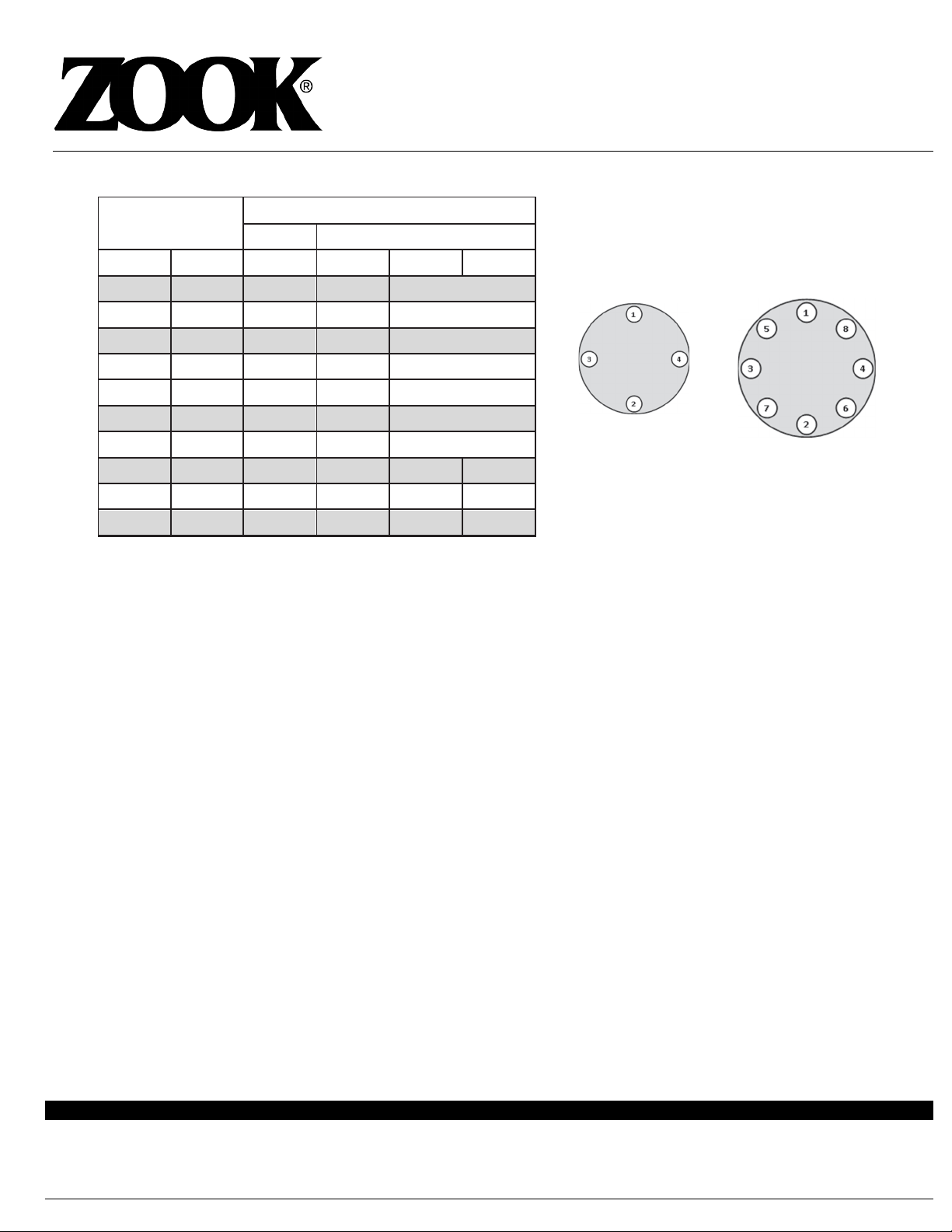
7) Determine the recommended bolting torque from Table 1.
8) Using a calibrated torque wrench, apply torque incrementally in a minimum of three (3) passes
[30%, 60%, 100% of specified recommended torque] using a crossing pattern tightening sequence
(see diagrams below). After following this sequence, a final tightening should be performed using a
circumferential pattern moving bolt-to-bolt to ensure that all bolts have been evenly torqued.
9) Verify parallelism is in accordance with 1) a. above.
10) Torqueing loss is inherent in any bolted joint. The combined effects of bolt relaxation, gasket
creep, vibration in the system, thermal expansion and elastic interaction during bolt tightening
contribute to torque loss. Companion flange torque values should be verified periodically at the
system temperature.

www.zookdisk.com
Serving America, Central & South America
16809 Park Circle Drive, Chagrin Falls,
Ohio 44022 USA
Toll Free: +1 800 543 1043
Phone: +1 440 543 1010
E-mail: [email protected]
Serving Europe, Middle East & Africa
Navigation House, Bridge Street
Killamarsh, Sheffield,
S21 1AL UK
Phone: +44 (0) 1909 560999
E-mail: sales.europe@zookdisk.com
Serving Canada
4400 South Service Rd,
Burlington, Ontario L7L 5R8 CA
Toll Free: +1 800 370 6057
Phone: +1 905 681 2885
E-mail: sales.canada@zookdisk.com
Serving Asia Pacific
Unit No.23A-05, Menara Landmark, No.12,
Jalan Ngee Heng
80000 Johor Bahru, Johor, Malaysia
Phone: +60 (7) 2910099
E-mail: sales.asia@zookdisk.com
Page 3 of 4RT2_InstallationGuide_022219
Safety Through Knowledge and Performance
INSTALLATION INSTRUCTIONS
Graphite and Metal Rupture Disk Holders
Rupture Disk Series: RT2, RT2T, RE2, RE2T and Variants
Table 1 – Torque Values Typical Bolt Tightening Sequences
4 Bolt Flange 8 Bolt Flange
Standard Conditions for Torque Calculations
a) The torque values provided above should be used with caution. Engineering judgment and experience is
needed to allow for proper interpretation. Due to the inherent variations in the coefficient of friction, both
in the threadsand between the nut face and clamped surface, there is no single “correct” tightening
torque for all circumstances.
A range of values can be determined however given the anticipated frictional scatter. The amount of
frictional scatter, which the engineer allows for when determining the clamp force and tightening torque,
should be based upon experimental results taken from the application.
b) Recommended torque values do not consider piping stress or alignment.
c) Consult ZOOK for recommended torque values for non-standard conditions.
Actual field conditions may differ from room temperature conditions on which the above torque values are based
on. In addition, these values are based on raised face welding neck flanges, free running treads and well
lubricated bolts with a coefficient of friction of µ =0.180, 1/8” thk compressed fiber gaskets with design seating
stress (y) of 4400 psi and gasket factor (m) of 5.2. Re-torqueing of bolts may be necessary to nullify loss caused
by gasket compression set. ASME Code Sect. VIII Div. 1 was followed for estimating required seating and
operating bolt loads.
NOMINAL
SIZE
TORQUE FT-LB (N-m)
ANSI DIN
NPS DN 150 PN6 PN10 PN16
125 9 (12.2) 7 (9.5) 9 (12.2)
1 ½ 40 12 (16.3) 12 (16.3) 15 (20.3)
250 17 (23.0) 14 (19.0) 17 (23.0)
2 ½ 65 30 (40.7) 30 (40.7) 30 (40.7)
380 34 (46.1) 34 (46.1) 17 (23.0)
4100 25 (33.9) 48 (65.1) 25 (33.9)
5150 46 (62.4) N/A 46 (62.4)
8200 64 (86.8) N/A 64 (86.8) 43 (58.3)
10 250 80 (108.5)
N/A 80 (108.5) N/A
12 300 80 (108.5) N/A 80 (108.5) N/A

www.zookdisk.com
Serving America, Central & South America
16809 Park Circle Drive, Chagrin Falls,
Ohio 44022 USA
Toll Free: +1 800 543 1043
Phone: +1 440 543 1010
E-mail: [email protected]
Serving Europe, Middle East & Africa
Navigation House, Bridge Street
Killamarsh, Sheffield,
S21 1AL UK
Phone: +44 (0) 1909 560999
E-mail: sales.europe@zookdisk.com
Serving Canada
4400 South Service Rd,
Burlington, Ontario L7L 5R8 CA
Toll Free: +1 800 370 6057
Phone: +1 905 681 2885
E-mail: sales.canada@zookdisk.com
Serving Asia Pacific
Unit No.23A-05, Menara Landmark, No.12,
Jalan Ngee Heng
80000 Johor Bahru, Johor, Malaysia
Phone: +60 (7) 2910099
E-mail: sales.asia@zookdisk.com
Page 4 of 4RT2_InstallationGuide_022219
Safety Through Knowledge and Performance
INSTALLATION INSTRUCTIONS
Graphite and Metal Rupture Disk Holders
Rupture Disk Series: RT2, RT2T, RE2, RE2T and Variants
Typical RT2 Series Installation
Flanges and flange gaskets – user supply. Outlet flange and gasket omitted for clarity.
The disk tag is designed to provide critical information about the rupture disk and should NOT be used as a handle
to hold, lift or adjust the assembly during installation. This practice can damage the disk resulting in failure of the
disk.
Holder Outlet
Rupture Disk
Vacuum Support
(Optional)
Holder Inlet
Gasket
Companion Flange
Flow Direction
This manual suits for next models
3