Zublin Swiss Garde 360 Premium 25050 User manual

User Manual
Ceiling-Mounting Motion Detector 360°
Swiss Garde 360 Premium (25050)

Warning!
- Any work on the main power supply must only be completed by trained specia-
lists.
- The product must be installed in accordance with installation guidelines/stan-
dards specific to your country.
- Disconnect the 230V power supply before starting the installation process.
- As a precautionary measure, the power supply of the light should always be fit-
ted with a (250VAC, 10A) type C fuse in accordance with EN60898-1.
- Faulty lamps may cause a short-circuit and thereby permanently damage the
device.
- Disconnect power prior to replacing a lamp.
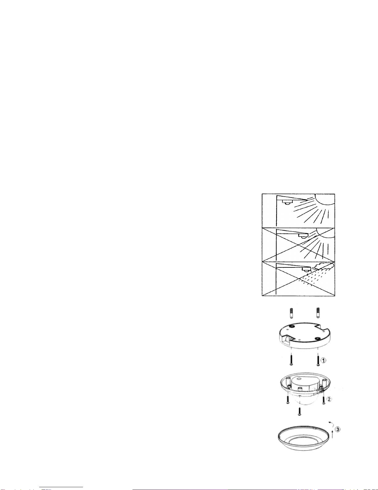
- To ensure the operational reliability of the detector, keep a minimal distance of
1m to lamps installed on the same height level.
- Lamps installed underneath the detector or in the detection area may disturb
the functionality. Keep the detector away from heating devices.
- In case of malfunction, such as continuous lighting, or false triggering please
refer to the troubleshooting section on page 7.
Function
The detector reacts to the motion of heat (positive or
negative in relation to the environment). If a person
approaches the monitored area, the device will turn on the
connected light automatically. If the person leaves the area,
the light will be switched off after the preset duration (short
impulse, 10 sec. to 20 min.).
The connected light will be turned on only when the
ambient light value is below the adjusted value.
Installation
The installation height should be about 2 to 4 m.
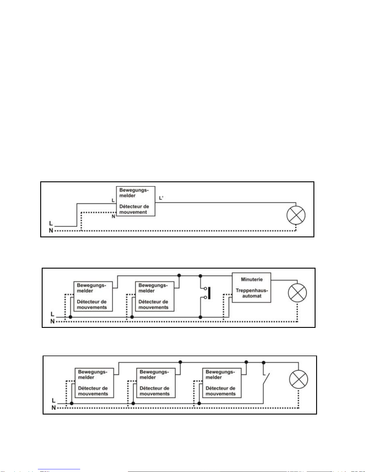
Wire the detector as follows:
phase / outer conductor (L) brown;
neutral-/ neutral conductor (N) blue; switching output /
switched phase/ outer conductor (L’) red
After wiring, screw and tighten the detector into the ceiling
mounting box. Ensure that no water intrusion along the cable is
possible.
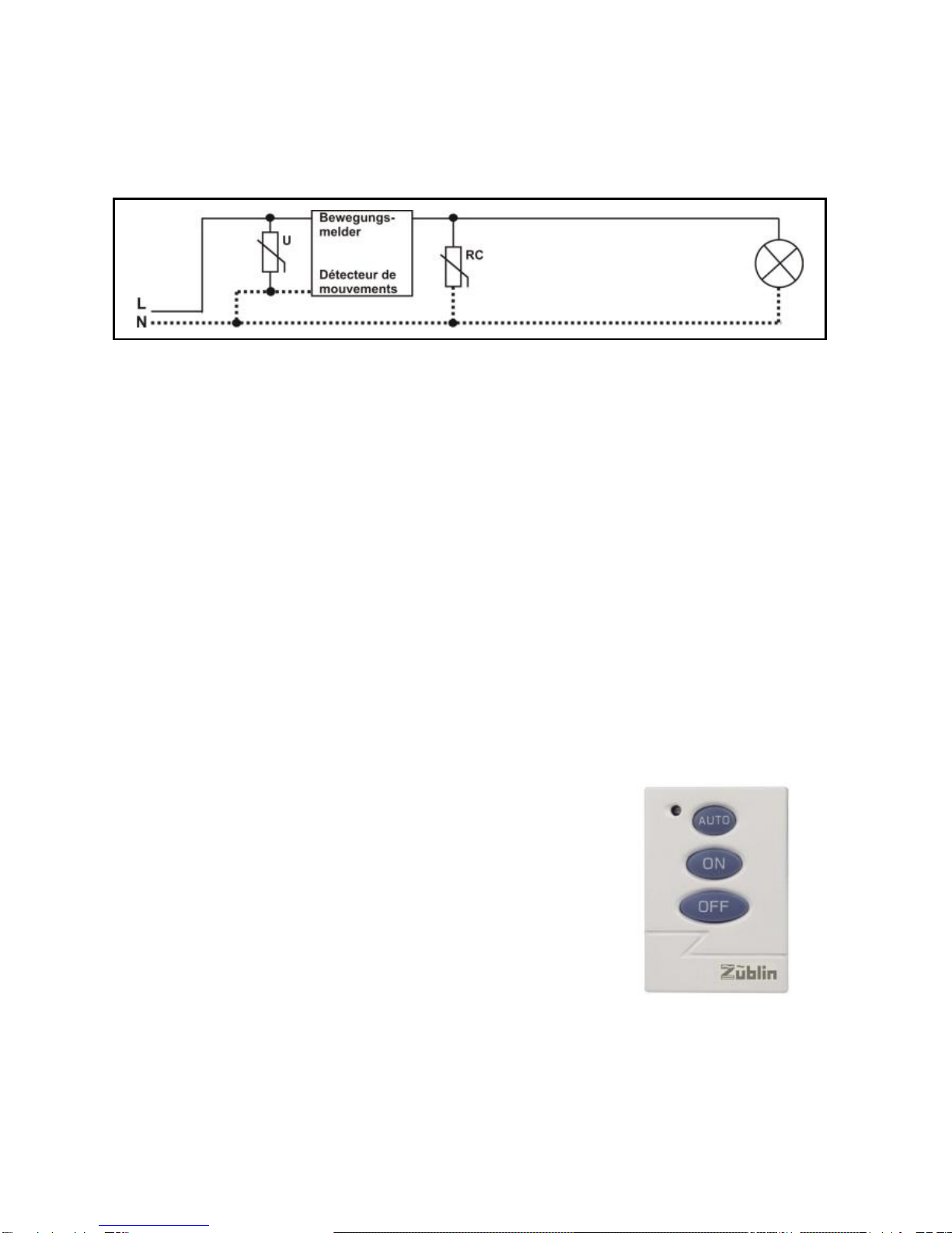
The device is operational after approx. 1 minute from connec-
ting to mains voltage. After this duration the detector can be
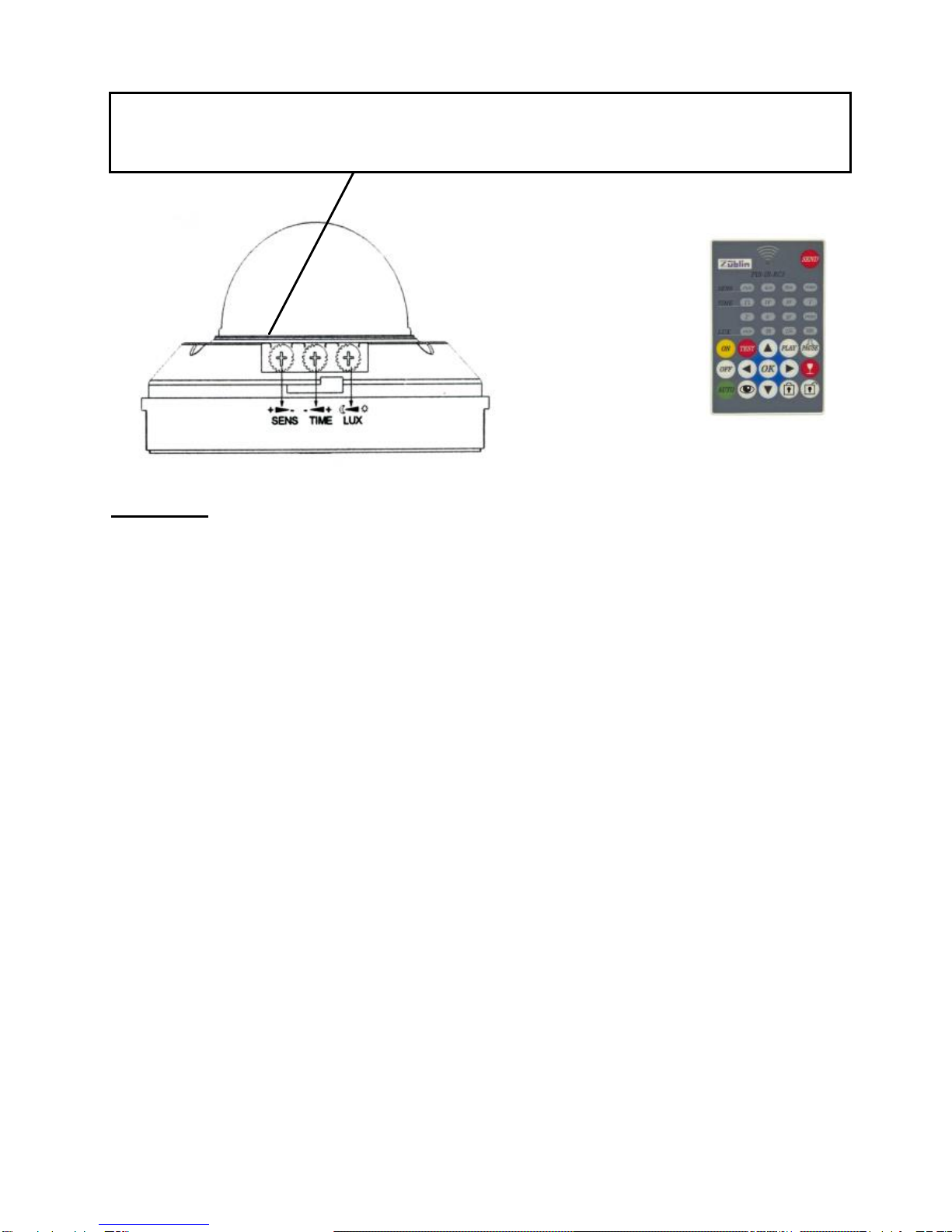
programmed either by P-IR remote control or by manipulating
potentiometers.
Potentiometer adjustments will only be accepted during a stable
working state. After programming, put the cover back on.
2

Connecting electrical loads
High inrush currents will considerably shorten the lifetime of the detector’s
in-built relay. Please verify the technical data provided by the lamp or
luminaires manufacturer concerning inrush currents, specifically with
compact fluorescent, fluorescent lamps, electronic ballast, etc. in order not
to overload the internal relay.
We recommend connecting a maximum of three to four motion detectors in
parallel. If the number of switching cycles is above average or in the event
of increased (inductive) loads, we recommend using the short pulse
function on the motion detector and switching the load via an external
staircase timer switch or contactor.
Wiring diagrams
Standard installation
Several devices in parallel in short impulse mode
(max. 3 to 4 devices) connected to a staircase timer switch.
Detectors connected in parallel, with additional wall switch to enable
permanent lighting.
3

Installation of an RC element, (between neutral conductor (N) and
switched phase L‘) in case of interferences by fluorescent lamps
(switch-off sparks) or by several detectors connected in parallel
(caused by capacitive current in the wires). Varistor (between neutral
conductor (N) und phase (L)) to reduce mains voltage peaks.
Accessory: 3-button remote control
Functions:
Auto = automatic operation (default)
ON = lights permanently ON *
OFF = lights permanently OFF *
* 6 hours duration, after which the detector
will go be back to automatic mode.
ON cannot be activated in short impulse mode!
4

Potentiometer controls overview
SENS (sensitivity/detection range)
Detection range adjustment max = approx. 30 m diameter (walking
person). Should the detector be too sensitive (triggering without
movement in the detection range), the sensitivity/range can be
reduced.
TIME
The timer determines for how long the lights will remain on following the
last movement in the detection area. Choices are between short
impulse (approx. 1 sec, approx. 20 sec. / 60 sec. break, selectable by
remote control only) and time delay (approx. 10, 30 sec., 1, 2, 6, 10, 20
min.). Recommendation: approx. 2 min. in staircases, 10 min. in
restrooms, etc.
LUX (twilight sensor)
The twilight sensor regulates the operating threshold (light value) of the
detector determining when the device should be activated. Minimum
value 5 lux (moon symbol): The detector will turn on the light at night.
Maximum value 2000 lux (sun symbol): The detector will turn on the
light during daytime as well.
Recommendation: approx. 5 lux in staircases, 200 lux in office spaces.
5
Red LED, flashing once upon detection, three times upon adjusting
TIME or LUX, or receiving a command from the remote control.
Attention! Manipulating LUX or TIME VR during a stable working
condition, values will be stored and become valid. Any values adjusted
by remote control will be overridden. Either manual values or values by
remote control may be active, mixing is not possible.
Accessory: P-IR
remote control
For functions
please refer to
separate remote
control manual.

Detection range
The 360° omnidirectional detection zone and the dense detection field
guarantee an optimal function. The range depends on the installation
height and walking direction (high sensitivity when cutting or changing a
switching segment).
Since the detector reacts to temperature differences between heat
source and ambient temperature, the response may vary depending on
the installation site (floor heating, hot environment, etc.).
top view
side view
6
frontal detection
NOT SENSITIVE
detection range =
approx. -50%
tangential detection
= SENSITIVE

Troubleshooting
error cause/amendment
light does not turn on: - twilight adjustment value too low
- connected lamp defective
- check mains power / fuses
detector triggers without - check detection area for potential reason /
light never turns causes of false triggering: draught, ani-
off: mals, heating, etc. may all provoke faulty
switching!
- detector is too sensitive, reduce the detec-
tion range sensitivity (by remote control or
VR) or cover disturbing segments on the
lens by adhesive tape.
- check distances to lamps (heat reflection
or direct light influence)
- connect RC element in parallel to transfor-
mers, relais, electric ballast
light flashes periodically / - non-compensated fluorescent lamps need
detector doesn’t reach an RC element or compensation conden-
proper working condition ser installed.
triggers or blocks at mains - install a Varistor between phase (L) and
voltage peaks: neutral (N) wires
light turns off even if motion - increase the TIME value (to maximum if
is detected needed).
turns the light on during - twilight adjustment set too high (set to
daytime a lower value). Respect 1 min. start-up!
- detector is installed in the shade
- consider changing the location of detector
After mains connection: the detector takes approx. 1 min. to reach a stable
working condition!
7

Technical data
Nominal power: 230V / 50Hz
Switching power: 2300W / 10A max. (cos φ = 1)
1150VA / 5A max. inductive (cos φ = 0,5)
Time adjustment: short impulse approx. 1 sec. (20/60 sec. break)
approx. 10 sec. to 20 min.
Twilight switch: 5 to 2000 lux or lux memory (via remote ctrl)
IR remote control: Auto / On / OFF (4 to 6 m range)
Detection range: ceiling mount 360°
(at ceiling height): 2.5 m = max. 12 m radius
3.0 m = max. 13 m radius
3.5 m = max. 14 m radius
4.0 m = max. 15 m radius
Rec. ceiling height: 2 to 4 m
Environmental temperature: -20 to +40 °C
Dimensions: Ø 125x73mm
IP protection: IP55, class II
Electronic Control
Induction in long installation wires (if several detectors connected in parallel) may
generate a considerable capacitive current on the switched phase. For electric
loads using only a small control current, such as staircase timer switches, this
may lead to permanent switching or general malfunctions. In order to minimise
the capacitive current, an RC element may be connected in parallel to the load.
Alternatively, a contactor, which is more tolerant to capacitive currents, may be
installed before the load. We recommend a maximum of four detectors
connected in parallel.
Do not dispose of electrical appliances in your
waste bin, use the collecting point of your
municipality, or return the old device to your
dealer.
8
Other Zublin Accessories manuals
Popular Accessories manuals by other brands

unotec
unotec 10H quick start guide

Benchcrafted
Benchcrafted Drawnknife Hone-O-Matic Drawsharp manual

Belkin
Belkin SPORTCOMMAND FOR IPOD user manual

VAF instruments
VAF instruments Viscosense 3 Instructions for installation, operation care and maintenance

NuAire
NuAire DRI-ECO-CO2 installation manual

Zte
Zte RSU82 S1900 Hardware installation