-2-
related international symbols used by the Meter and the
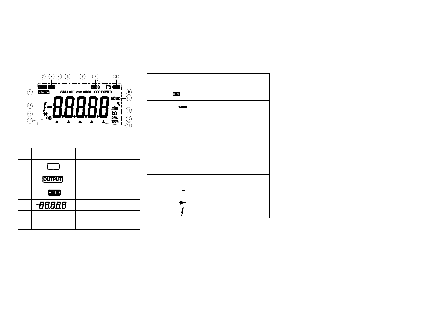
Manual, please read Table 1-1 for reference.
Warning
l Do not use the meter if it is damaged. Before using
the meter, inspect the case. Look for cracks or
missing plastic. Pay particular attention to the
insulation surrounding the connectors.
l Make sure the battery door is closed and latched
before operating the meter.
l Remove test leads from the meter before opening the
battery door.
l Inspect the test leads for damaged insulation or
exposed metal. Check test leads before using the
meter. Replace the damaged leads before use.
l Do not use the meter if it operates abnormally.
Protection may be impaired. When in doubt, have the
meter serviced.
l Do not operate the meter around explosive gas, vapor,
or dust.
l Use only type AA batteries, properly installed in the
meter case to power the meter.
l Use caution when working above 30V ac rms, 42V ac
pk, or60V dc. Such voltages pose a shock hazard.
l When using the probes, keep fingers behind the
finger guards on the probes.
l Connecting the common test lead before connecting
the live test lead. When disconnecting test leads,
disconnect the live test lead first.
l Read carefully and make sure well understanding of
this Manual before use.
l Make sure the requirements in the Manual are strictly
followed and keep the Manual for reference whenever
needs.
l Mis-operation may cause accidents and damages to
the Meter in testing. Caution
To avoid possible damage to the Meter or to equipment
under test:
l Make sure the rotary switch is in the right position,
disconnect the testing leads and the circuit under test
before rotating, conversion in testing is prohibited in
case of damaging the Meter.
l Cut all the power off and release electricity fully from
all capacitor before testing online resistance, biode
and continuity.
l Check fuse in the Meter before testing current (See
Section Five Replacing Fuse). Cut off the power
before connection. Remember: when testing current,
connect the Meter with the Circuit in series. Do not
connect testing leads to any circuit in parallel.
l Do not use the Meter if symbol displays.
l Do not store or use the Meter in high temperature,
high moisture, explosive, inflammable, strong
electromagnetic environment and dew or direct
sunlight place.
l Do not use abrasive or solvent to clean the Meter, use
a damp cloth or neutral detergent instead.