Page 3
Safety Precautions
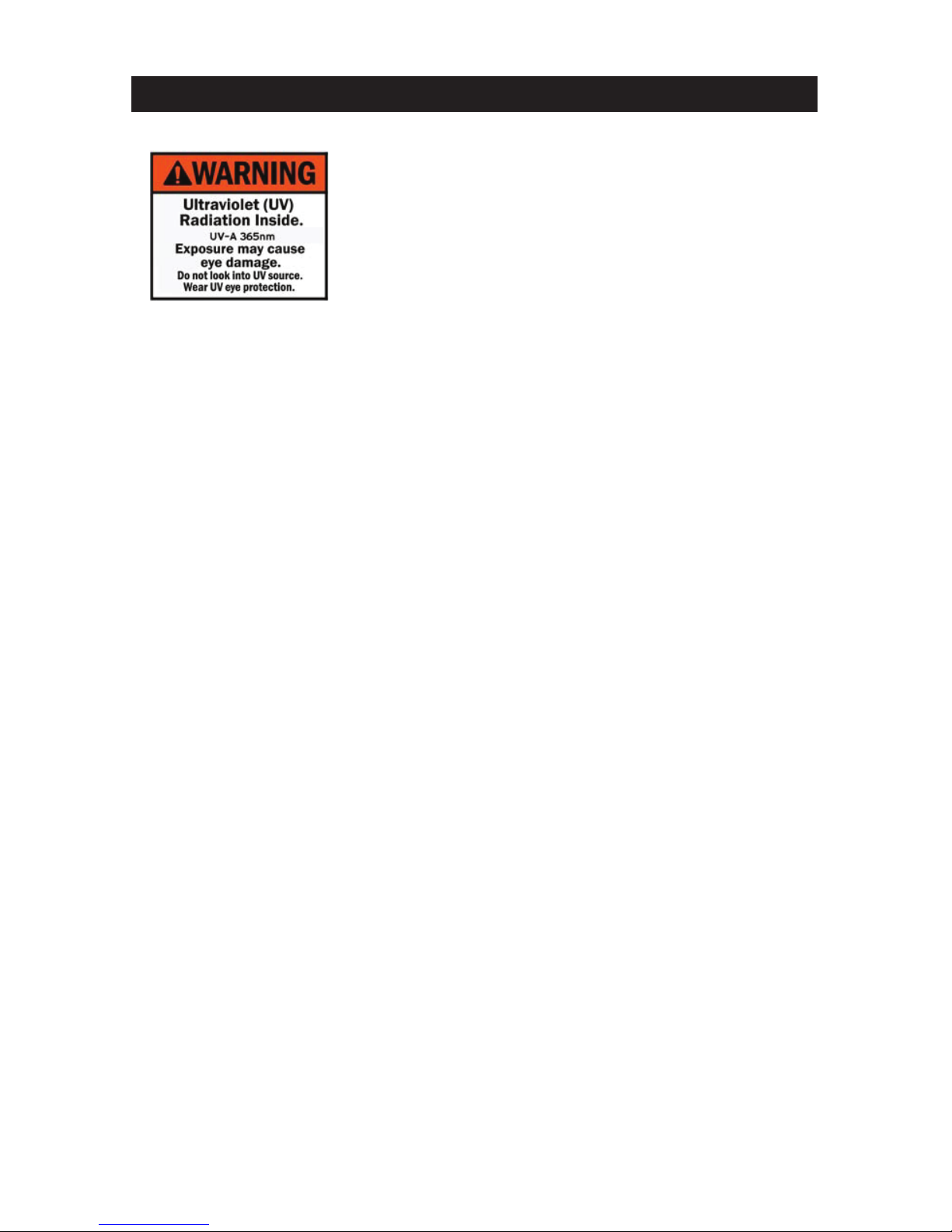
Ultraviolet Radiation Warning:
The F8-B2(blacklight) fixture contains a high intensity
LED ultraviolet emitter which is concentrated with a fresnel
lens. When this fixture is used in accordance with the
manufacturer’s operating instructions, no hazards exist
to most people standing within the beam of the fixture.
However, individuals suffering from a range of sunlight
exposure disorders, aphakic and pseudoaphikic, or those
individuals receiving photosensitive medication may receive discomfort if exposed
to ultraviolet light. For reflective, not direct use. Avoid too frequent or too lengthy
exposure. Exposure can cause eye and skin injury and allergic reactions.
Repeated exposure may cause chronic sun damage and skin cancer. Do not look
directly into the fixture while in operation. Wear protective eyewear. Failure to use
protective eyewear may result in severe burns or long-term injury to the eyes.
This fixture emits Ultraviolet Radiation (UVA) at a primary wavelength of 365nm. The
radiation emitted is not in the visible spectrum and can cause eye and skin damage!
Do not look directly into the lens during operation! Please use caution and wear eye
protection and protective clothing for anything other than temporary exposure. This
fixture is meant to be used at distances of over 10 feet (3m).
IP Rating:
The F8-B2is rated IP54 for weather resistance: Ingress of dust is not entirely
prevented, but it will not interfere with satisfactory operation. Splashing water or
light rain or snow will also have no harmful effect. While the F8 is protected
against light moisture and dust exposure, please protect the instrument when
shooting in extreme conditions and note that the instrument is not rated to be
submerged in water, or exposed to prolonged periods of moisture. Always use your
best judgment and protect the instrument from sustained moisture exposure.
• To reduce the risk of electrical shock or fire, do not submerge this fixture in water.
• Do not spill large amounts of water or other liquids into or on to your fixture.
• Do not attempt to operate this unit if the power cord has been frayed or
broken. Do not attempt to remove or break off the ground prong from the
electrical cord. This prong is used to reduce the risk of electrical shock and fire in
case of an internal short.
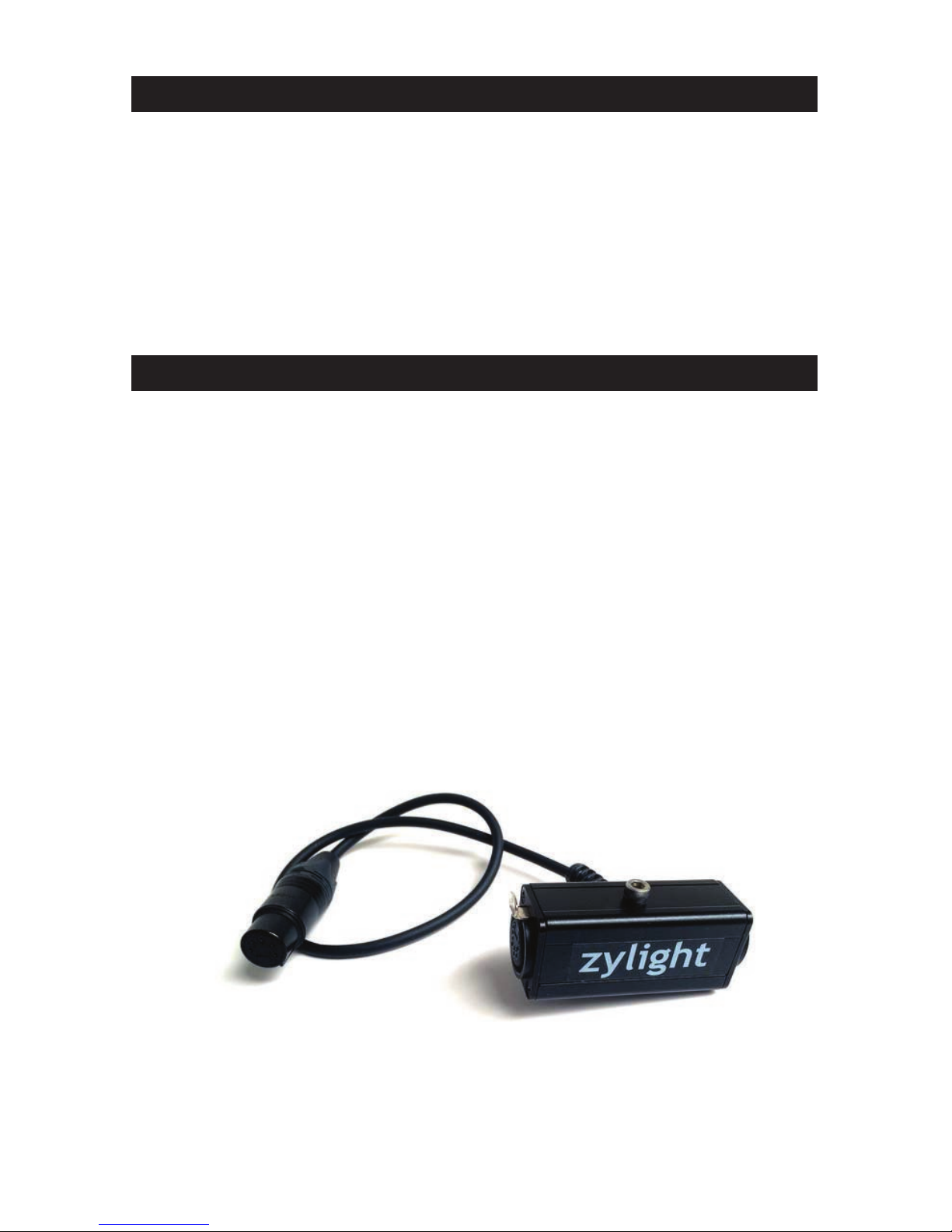
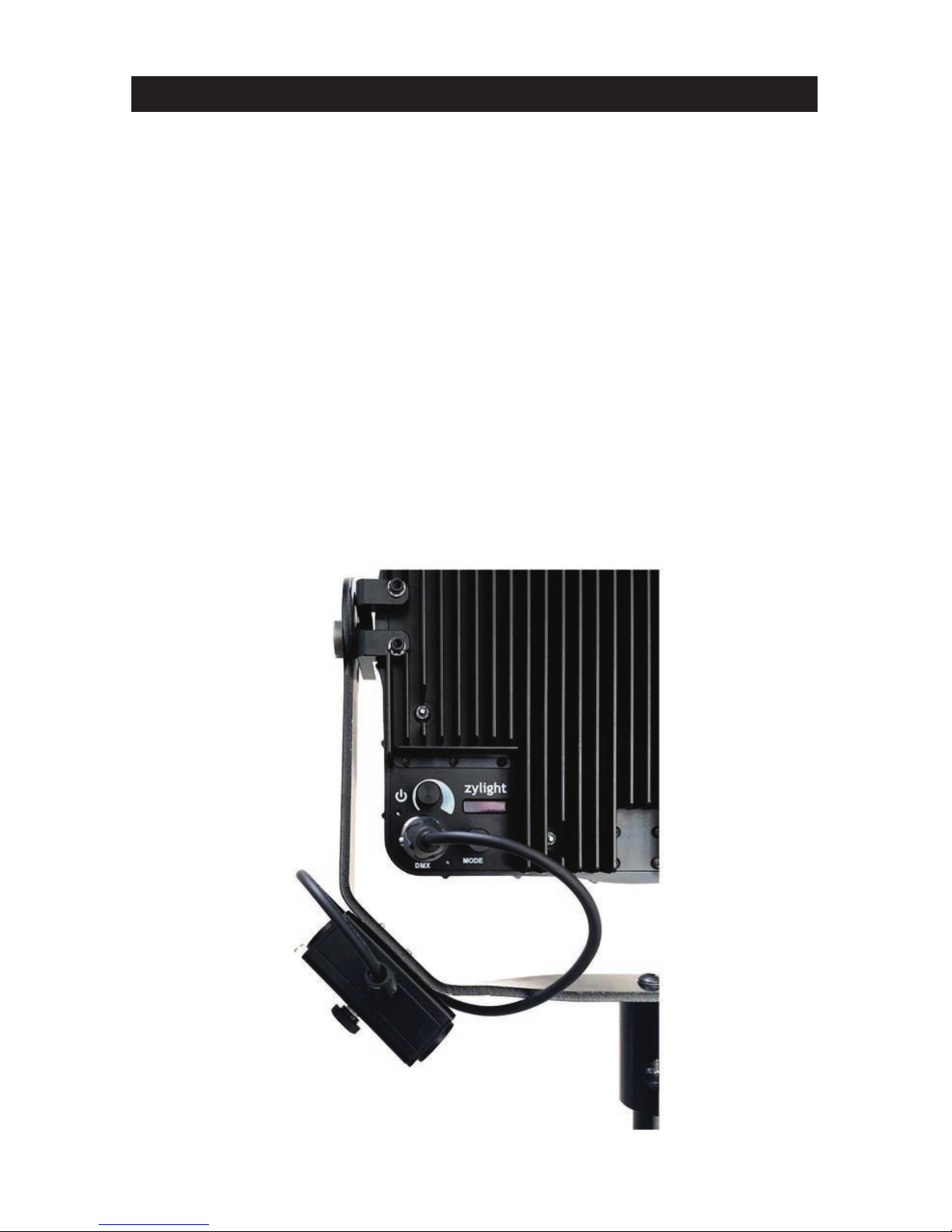
• Disconnect from main power before making any type of connection.
• Do not remove the lens under any conditions. There are no user serviceable parts
inside.
• Never operate this fixture if the Fresnel lens is removed.
• Never plug this unit in to a dimmer pack.
• Always be sure to mount this fixture in an area that will allow proper ventilation.
Allow at least 6” (15cm) between this device and a wall.
Page 3
Safety Precautions
Ultraviolet Radiation Warning (F8-B Only):
The F8-B (blacklight) fixture contains a high intensity led
ultraviolet emitter which is concentrated with a fresnel
lens. When this fixture is used in accordance with the
manufacturers operating instructions, no hazards exist to
most people standing within the beam of the fixture.
However, individuals suffering from a range of sunlight
exposure disorders, aphakic and pseudoaphikic, or those
individuals receiving photosensitive medication may receive discomfort if exposed
to ultraviolet light. For reflective, not direct use. Avoid too frequent or too lengthy
exposure. Exposure can cause eye and skin injury and allergic reactions. Repeated
exposure may cause chronic sun damage and skin cancer. Do not look directly into
the fixture while in operation. Wear protective eyewear. Failure to use protective
eyewear may result in severe burns or long-term injury to the eyes.
This fixture emits Ultraviolet Radiation (UVA) at a primary wavelength of 365nm.
The radiation emitted is not in the visible spectrum and can cause eye and skin
damage! Do not look directly into the lens during operation! Please use caution and
wear eye protection and protective clothing for anything other than temporary
exposure. This fixture is meant to be used at distances of over 10 feet (3m).
IP Rating:
The F8 is rated IP54 for weather resistance: Ingress of dust is not entirely
prevented, but it will not interfere with satisfactory operation. Splashing water or
light rain or snow will also have no harmful effect. While the F8 is protected
against light moisture and dust exposure, please protect the instrument when
shooting in extreme conditions and note that the instrument is not rated to be
submerged in water, or exposed to prolonged periods of moisture. Always use your
best judgment and protect the instrument from sustained moisture exposure.
• To reduce the risk of electrical shock or fire, do not submerge this fixture in
water.
• Do not spill large amounts of water or other liquids into or on to your fixture.
• Do not attempt to operate this unit if the power cord has been frayed or
broken. Do not attempt to remove or break off the ground prong from the
electrical cord. This prong is used to reduce the risk of electrical shock and fire
in case of an internal short.
• Disconnect from main power before making any type of connection.
• Do not remove the lens under any conditions. There are no user serviceable
parts inside.
• Never operate this fixture if the Fresnel lens is removed.
• Never plug this unit in to a dimmer pack.
• Always be sure to mount this fixture in an area that will allow proper
ventilation. Allow at least 6" (15cm) between this device and a wall.
• Do not attempt to operate this fixture if it becomes damaged.