2M Technology VSC-3000A User manual

Operating Manual
Solar Trailer

2
Unit Model Number:
Unit Serial Number:
INTRODUCTION
DO NOT MODIFY or use this equipment for any application other than which it was designed for.
WHEN CALLING FOR PARTS OR TECHNICAL SERVICE INFORMATION, PLEASE
HAVE YOUR UNIT SERIAL NUMBER READY TO HELP FACILITATE YOUR CALL.
2M Technology recommends that a trained and licensed professional perform all electrical wiring and testing functions.
2M TECHNOLOGY
Keep a copy of this manual with the unit at all times. Additional copies are available from 2M TECHNOLOGY,
or can be found at www.2mtechnology.net. Operators manual for MPPT controller, inverter, battery charger
and backup generator were also supplied with the unit at the time of shipment from the factory. The manual
provides detailed operation and maintenance procedures.
802 Greenview Dr | Grand Prairie TX 75050
USA
www.2mtechnology.net
Phone: +1 866 708 5401
Fax: +1 972 999 4113
This manual provides information and procedures to safely operate and maintain the solar trailer. For your own
safety and protection from physical injury, carefully read, understand, and observe the safety instructions
described in this manual. The information contained in this manual was based on machines in production at the
time of publication. 2M Technology reserves the right to change any portion of this information without notice.

TABLE OF CONTENTS
Page
INTRODUCTION ..............................................................................................................................2
TABLE OF CONTENTS ...................................................................................................................3
SAFETY NOTES ........................................................................................................................... 4
OPERATING SAFETY .....................................................................................................................4
SERVICE SAFETY .........................................................................................................................5
TOWING SAFETY ..........................................................................................................................6
UNIT SERIAL NUMBER LOCATIONS ..............................................................................................6
SAFETY SYMBOL SUMMARY .......................................................................................................7
SPECIFICATIONS .................................................................................................................... 8 - 11
SOLAR TRAIER SET UP ............................................................................................................... 12
SOLAR PANELS SLIDING OUT............................................................................................ 13 - 14
RASING THE TOWER........................................................................................................... 15 - 18
ELECTRICAL OPERATION ................................................................................................... 19 - 20
MIAN CONTROL PANEL COMPONENTS ............................................................................. 21 - 22
SOLAR PANELS RETRACT.................................................................................................... 23 - 24
LOWER THE MAST .................................................................................................................. 25 -28
ELECTRICAL OPERATION .......................................................................................................... 29
TRAILER ASSEMBLY............................................................................................................. 30 - 31
TRAILER CABINET ASSEMBLY............................................................................................... 32 - 33
3
TRAILER LIGHTS WIRING (AUSTRALIA) ...................................................................................... 34
TRAILER LIGHTS WIRING (USA) ............................................................................................... 35

SAFETY NOTES
This is the safety alert symbol. It is used to alert you to potential personal injury hazards.
Obey all safety messages that follow this symbol to avoid possible injury or death.
This manual contains DANGERS, WARNINGS, CAUTIONS, NOTICES and NOTES which must be
followed to prevent the possibility of improper service, damage to the equipment, personal injury or death.
The following formatting options will apply when calling the readers attention to the DANGERS, WARN-
INGS, CAUTIONS, NOTICES and NOTES.
DANGER
INDICATES A HAZARDOUS SITUATION WHICH, IF NOT AVOIDED,
WILL RESULT IN DEATH OR SERIOUS INJURY.
WARNING
Indicates a hazardous situation which, if not avoided,
could result in death or serious injury.
CAUTION
Indicates a hazardous situation which, if not avoided, may result in minor or moderate injury.
NOTICE
Indicates a hazardous situation which, if not avoided,
may result in property or equipment damage.
Note: Notescontainadditionalinformationimportanttoaprocedureandwillbefoundwithintheregular
text body of this manual.
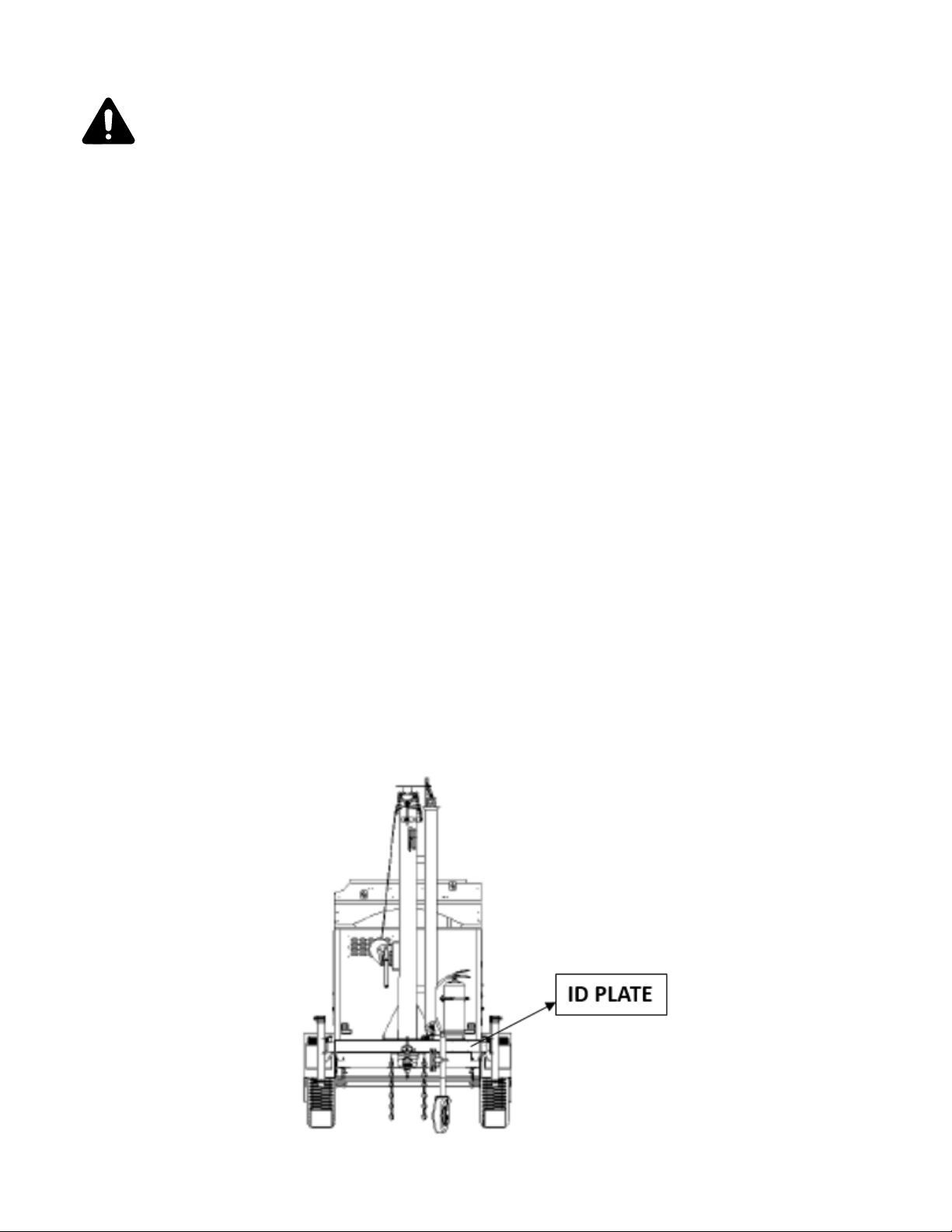
OPERATING SAFETY
Before using the solar trailer be sure you read and understand all of the instructions! This equipment
was designed for specific applications; DO NOT modify or use this equipment for any application other than
which it was designed for. Equipment operated improperly or by untrained personnel can be dangerous!
Read the operating instructions and familiarize yourself with the location and proper use of all instruments
and controls. Inexperienced operators should receive instruction from someone familiar with the equipment
before being allowed to operate or set up the solar trailer. The following points should be practiced at all
times:
•The area immediately surrounding the solar trailer should be dry, clean, and free of debris.
•Position and operate the solar trailer on a firm, level surface.
•NEVER operate a unit in need of repair.
•Lower tower when not in use, or if high winds or electrical storms are expected in the area.
•Make certain solar trailer is well grounded and securely fastened to a good earthen ground.
•When the mast is raising, make sure area above trailer is open and clear of overhead wires and
obstructions.
•Keep area beside trailer clear of people while raising and lowering mast!
•Trailer must be leveled and outriggers extended before raising tower. Outriggers must remain ex-
tended while tower is up.
•If for any reason any part of mast hangs up or winch cable develops worn while raising or lowering
tower, STOP immediately and replace it.
•NEVER remove safety pin or pull mast locking pin while tower is up!
•NEVER use tower if insulation on electrical cord is cut or worn through.
•If used in dense crowds, please set up guards 5 meters away from the unit.
•NEVER take power directly from the batteries.
•If not being used for a long time, please turn off the breaker for the batteries.
•
•
4

5
This unit includes solar modules and batteries which are with high voltage circuits capable of causing
serious injury or death. Only a qualified electrician should troubleshoot or repair electrical problems
occurring in this equipment.
•Before servicing solar trailer, make sure the breakers for solar modules, batteries and load are
turned OFF. Disconnect the solar panels and batteries.
•NEVER allow water to accumulate around the base of the solar trailer. If water is present, DO NOT
service!
•NEVER wash the unit with a power washer or high pressure hose.
•Please wear goggles and insulating gloves, using insulation wrench to replace the batteries.
•NEVER disassemble and repair the mast in uneven place. The mast must be hung and installed
with equipment.
•NEVER replace the tyres and outriggers or adjust and fix the brake system in uneven place.
•NEVER replace the manual (electric/hydraulic cylinder) winch when the mast is extending.
•Make sure slings, chains, hooks, jacks, and other types of lifting devices are attached securely and
have enough weight-bearing capacity to lift or hold the equipment safely. Always remain aware of
the position of other people around you when lifting the equipment.
•NEVER operate electric winch in neutral position when the mast is extending. (Optional electric winch is
selected.)
• During mast extending, once the hole for locking pin aligns, stop operating the manual/electric winch.
• During solar charge process, do not unplug each panels and the connectors for solar input on the trailer.
It will lead to severe personal injury and equipment damage.
•NEVER put conductive metal objects on the batteries.
• Do not forget to insert the safety locking pin when cranking up the outrigger.
SERVICE SAFETY

Towing a trailer requires care! Both the trailer and vehicle must be in good condition and securely fas-
tened to each other to reduce the possibility of an accident. Also, some countries require that trailers
be registered and licensed. Contact your local Department of Transportation office to check on license
requirements for your particular unit.
•Check that the hitch and coupling on the towing vehicle are rated equal to, or greater than, the trailer's
"gross vehicle weight rating" (GVWR).
•Check tires on trailer for tread wear, inflation, and condition.
•Inspect the hitch and coupling for wear or damage. DO NOT tow trailer using defective parts!
•Make sure the trailer hitch and the coupling are compatible. Make sure the coupling is securely
fastened to the vehicle.
•Connect safety chains in a crossing pattern under the tongue and if the trailer is with electric brake,
attach the breakaway cable TO THE REAR BUMPER OF THE TOWING VEHICLE. Do not attach
the cable to the trailer hitch.
•Make sure directional and brake lights on the trailer are connected and working properly.
•Check that all lug nuts holding wheels on are tight and that none are missing.
•Maximum recommended speed for highway towing is 45 m.p.h (72km/h). Recommended off-road
towing speed is not to exceed 10 m.p.h. or less depending on terrain.
When towing, maintain extra space between vehicles and avoid soft shoulders, curbs, and sudden lane
changes. If you have not pulled a trailer before, practice turning, stopping, and backing up in an area
away from heavy traffic.
A film of grease on the coupler will extend coupler life and eliminate squeaking. Wipe the coupler clean
and apply fresh grease each time the trailer is towed.
TOWING SAFETY
UNIT SERIAL NUMBER LOCATIONS
Refer to the locations illustrated below to find the unit ID plate. Important information, such as the unit serial
number, GVWR and GAWR for your trailer are found on the plate. Record the information from the plate, so it is
available if it is lost or damaged. When ordering parts or requesting technical service information, you may be
asked to specify this information.
6

7
SAFETY SYMBOL SUMMARY
This equipment has been supplied with numerous safety and operating decals. These decals provide important
operating instructions and warn of dangers and hazards.
Electricity storage devices inside. Contact a
qualified electrician for service or to open
electrical cabinet. Electric shock will cause
serious injury or death.
Always keep tension on steel wires! Slack
may cause wire damage and
excessive wear!
Trailer Level Trailer Not Level
Max 11°Incline Max 6°Incline
Do not exceed trailer installation
angles as below.
Contact with overhead electric wire will cause
serious injury or death. Do not place the
trailer under electric wire.
Forklift here only.
Pinch point area.
Anchor/tie down point.
Crush hazard! A falling top
device can cause death or
serious injury.
Crush hazard! A falling
mast can cause death
or serious injury.
Fix with pin when mast
completely extends.
Read and understand the
supplied operator’s manual
before operating unit.
Plug Out
Place the 7-pin plug to the
required position after it
comes across the
drawbar tube.
When towing trailer, pull the
jockey wheel to horizontal
position.
Stop operating mast when
the warning area appears.

SPECIFICATIONS
Equipment Details
Solar Panel 3 x 200W 2 x 325W 3 x 325W
4 x 150Ah/ 4 x 150Ah/ 4 x 200Ah/
4 x 200Ah 4 x 200Ah 6 x 150Ah/
6 x 200Ah
Trailer Type Single Axle Single Axle Single Axle
No brake/
Mechanical Brake/
Electric Brake
No brake/
Mechanical Brake/
Electric Brake
Mechanical Brake/
Electric Brake
Tire and Rim Size 15" 15" 15"
Stabiliser Supports 4 x Manual 4 x Manual 4 x Manual
Drawbar A Frame A Frame A Frame
Tow Hitch 50mm ball/70mm ring 50mm ball/70mm ring 50mm ball/70mm ring
Mud Guard/Wheel
Chock Special Design Special Design Special Design
N/A
3kW diesel generator
5kW diesel generator
3kW gasoline generator
Mast Details
Mast
Raise/Extension Manual/Electric/Hydraulic Manual/Electric/Hydraulic Manual/Electric/Hydraulic
Safety Auto Lock/Sensor/Safety
Valve
Auto Lock/Sensor/Safety
Valve
Auto Lock/Sensor/Safety
Valve
Mast Height (m) 6m/7.5m/9m optional 6m/7.5m/9m optional 6m/7.5m/9m optional
Mast 360 Degrees Optional Optional Optional
Coil Cable Optional Optional Optional
Wind Rating Speed 100km/h 100km/h 100km/h
Tower Dimensions
Length 3600mm 3400mm 4040mm
Width 1470mm 1490mm 1780mm
Height 2450mm 2425mm 2518mm
Weight 1050kg 643kg 1220kg
Backup Generator N/A N/A
Battery (optional)
Brake (optional)
8
MODEL 2MVSC-3000A2MVSC-3500A2MVSC-4000A

9
SPECIFICATIONS
Equipment Details
Solar Panel 3 x 325W 4 x 325W 4 x 325W
4 x 200Ah 4 x 200Ah 6 x 150Ah
6 x 150Ah 6 x 150Ah 8 x 150Ah
8 x 150Ah 8 x 150Ah 8 x 200Ah
Trailer Type Single Axle Single Axle Dual Axle
Mechanical Brake/
Electric Brake
Mechanical Brake/
Electric Brake
Mechanical Brake/
Electric Brake
Tire and Rim Size 15" 15" 15"
Stabiliser Supports 4 x Manual 4 x Manual 4 x Manual
Drawbar A Frame A Frame A Frame
Tow Hitch 50mm ball/70mm ring 50mm ball/70mm ring 50mm ball/70mm ring
Mud Guard/Wheel
Chock Special Design Special Design Special Design
3kW diesel generator
5kW diesel generator
3kW gasoline generator
N/A
3kW diesel generator
5kW diesel generator
3kW gasoline generator
3kW diesel generator
5kW diesel generator
3kW gasoline generator
Mast Details
Mast
Raise/Extension Manual/Electric/Hydraulic Manual/Electric/Hydraulic Manual/Electric/Hydraulic
Safety Auto Lock/Sensor/Safety
Valve
Auto Lock/Sensor/Safety
Valve
Auto Lock/Sensor/Safety
Valve
Mast Height (m) 6m/7.5m/9m optional 6m/7.5m/9m optional 6m/7.5m/9m optional
Mast 360 Degrees Optional Optional Optional
Coil Cable Optional Optional Optional
Wind Rating Speed 100km/h 100km/h 100km/h
Tower Dimensions
Length 4100mm 4100mm 4470mm
Width 1880mm 2100mm 2030mm
Height 2520mm 2520mm 2520mm
Weight 1380kg 1400kg 1750kg
Backup Generator
Battery (optional)
Brake (optional)
MODEL 2MVSC-4000B2MVSC-5000A2MVSC-5000B

SPECIFICATIONS
Equipment Details
Solar Panel 4 x 325W 4 x 325W 8 x 325W
4 x 200Ah 6 x 150Ah 12 x 150Ah
6 x 150Ah 8 x 150Ah 16 x 150Ah
8 x 150Ah 8 x 200Ah
Trailer Type Single Axle Dual Axle Dual Axle
Mechanical Brake/
Electric Brake
Mechanical Brake/
Electric Brake
Mechanical Brake/
Electric Brake
Tire and Rim Size 15" 15" 15"
Stabiliser Supports 4 x Manual 4 x Manual 4 x Manual
Drawbar A Frame A Frame A Frame
Tow Hitch 50mm ball/70mm ring 50mm ball/70mm ring 50mm ball/70mm ring
Mud Guard/Wheel
Chock Special Design Special Design Special Design
3kW diesel generator
5kW diesel generator
3kW gasoline generator
3kW diesel generator
5kW diesel generator
3kW gasoline generator
Mast Details
Mast
Raise/Extension Manual/Electric/Hydraulic Manual/Electric/Hydraulic Manual/Electric/Hydraulic
Safety Auto Lock/Sensor/Safety
Valve
Auto Lock/Sensor/Safety
Valve
Auto Lock/Sensor/Safety
Valve
Mast Height (m) 6m/7.5m/9m optional 6m/7.5m/9m optional 6m/7.5m/9m optional
Mast 360 Degrees Optional Optional Optional
Coil Cable Optional Optional Optional
Wind Rating Speed 100km/h 100km/h 100km/h
Tower Dimensions
Length 4100mm 4470mm 4700mm
Width 2030mm 2100mm 2150mm
Height 2520mm 2520mm 2500mm
Weight 1500kg 1850kg 2350kg
Battery (optional)
Brake (optional)
Backup Generator N/A
10
MODEL 2MVSC-6000C2MVSC-6000D2MVSC-6000A

11
SPECIFICATIONS
Equipment Details
Solar Panel 8 x 325W 8 x 325W
12 x 150Ah 12 x 150Ah
16 x 150Ah 16 x 150Ah
Trailer Type Dual Axle Triple Axle
Mechanical Brake/
Electric Brake
Mechanical Brake/
Electric Brake
Tire and Rim Size 15" 15"
Stabiliser Supports 4 x Manual 1 x Manual
Drawbar A Frame A Frame
Tow Hitch 50mm ball/70mm ring 50mm ball/70mm ring
Mud Guard/Wheel
Chock Special Design Special Design
3kW diesel generator
5kW diesel generator
3kW gasoline generator
20kW diesel generator
40kW diesel generator
60kW diesel generator
80kW diesel generator
Mast Details
Mast
Raise/Extension Manual/Electric/Hydraulic Manual/Electric/Hydraulic
Safety Auto Lock/Sensor/Safety
Valve
Auto Lock/Sensor/Safety
Valve
Mast Height (m) 6m/7.5m/9m optional 6m/7.5m/9m optional
Mast 360 Degrees Optional Optional
Coil Cable Optional Optional
Wind Rating Speed 100km/h 100km/h
Tower Dimensions
Length 4850mm 5850mm
Width 2150mm 2150mm
Height 2500mm 2450mm
Weight 2400kg 4500kg
Battery (optional)
Brake (optional)
Backup Generator
MODEL 2MVSC-7000B2MVSC-7000C

1. Place the trailer on firm ground that is relatively flat. This will make it easier to level the tower. Apply the hand
brake and block the wheels on the trailer to keep it from moving.
2. Connect a good earthen ground to the grounding stud on the base of mast.
3. Pull the locking pin on the jockey wheel and rotate it 90º until the spring loaded pin snaps back into place.
Turn the jack handle anticlockwise to raise the trailer drawbar off of the towing vehicle.
4. Pull the locking pins on the outriggers and extend each outrigger until the locking pin snaps back into place
(A).Pull out the locking pin in the bottom of the outrigger and fit it to the third hole above (B). Apply the same
action for the other 3 outriggers. Turn the jack handle clockwise to start leveling the trailer. Adjust all four jacks
by turning their handles clockwise until they are firmly in contact with the ground and the trailer is as level as
possible (C). (D is the level meter.)
SOLAR TRAILER SET UP
WARNING
The tower extends up to 30 ft (9.14 m). Make sure area
above the trailer is open and clear of overhead wires and
obstructions.
ABCD
Jockey
Wheel
Stabiliser Block the Chock
Mast
12

1. Unlock the solar panels (A), press the auto-lock for solar slides (B) and pull the panels to the outermost
position and make sure it is locked in place (C).
2. Connect the solar panel connectors to those plugs on the cabinet. Turn on the breakers for solar panels and
batteries on the control panel.
NOTICE
Under charging condition, make sure the solar panels are faced to the
direction of the sun, no shading and the surface is clean.
NOTICE
Do not operate the unit in the dangerous area where there are macadams fly and under weather
condition with strong wind
. It will damage the solar panels.
WARNING
Do not unplug the solar panel connectors when it is under charging
condition. (It may cause personal injury.)
ABC
13
SOLAR PANELS SLIDING OUT

1. Unlock the solar panels (A), press the auto-lock for solar slides (B) and pull the panels to the outermost
position and make sure it is locked in place (C).
NOTICE
Under charging condition, make sure the solar panels are faced to the
direction of the sun, no shading and the surface is clean.
NOTICE
Do not operate the unit in the dangerous area where there are macadams fly and under weather
condition with strong wind. It will damage the solar panels.
WARNING
Do not unplug the solar panel connectors when it is under charging
condition. (It may cause personal injury.)
2. Connect the solar panel connectors to those plugs on the cabinet. Turn on the breakers for solar panels and
batteries on the control panel.
3. Check oil tank, valve blocks, hydraulic cylinder, hoses and oil joints. Make sure there is no leakage and
enough hydraulic oil in the tank. Then press the lifting button on the controller to adjust the solar panels to the
required angle.
AB C
14
SOLAR PANELS SLIDING OUT AND ANGLE ADJUSTMENT BY HYDRAULIC SYSTEM

1. Before raising the tower it is be necessary to install the top devices and adjust them to the required condition.
2. Check mast ropes for excessive wear or damage. Make sure the ropes are properly centered in each pulley.
Check the mast electrical cord for damage.
WARNING
The trailer must be leveled with the outriggers extended before raising the tower. The outriggers
must remain extended while the tower is up. Failure to level the trailer or extend the outriggers
will severely reduce the stability of the unit and could allow the tower to tip and fall.
WARNING
Do not operate the unit if the insulation on the electrical cord is cut or worn through.
Bare wires in contact with the mast or frame may energize the trailer and cause
electrocution. Repair or replace cord.
3. Before raising the tower, make sure the steel ropes are orderly and tightened (A). If slack, it will lead to
steel ropes wear and even breakage. Crank up the mast clockwise (B) and extend it to the required height. If it is
extended to the maximum height, please insert the safety locking pin (C). Extend the mast slowly, making sure
that the electrical cord is extending at the top sections of the mast. If, for any reason, the cable begins to develop
slack or any of the tower sections get stuck, STOP IMMEDIATELY and contact an authorized service center.
15
ABC
RAISING THE TOWER

16

1. Set up and level the solar trailer as described on page 12.
2. Before raising the tower it is be necessary to install the top devices and adjust them to the required
condition.
WARNING
The trailer must be leveled with the outriggers extended before raising the tower. The outriggers
must remain extended while the tower is up. Failure to level the trailer or extend the outriggers
will severely reduce the stability of the unit and could allow the tower to tip and fall.
3. Check mast ropes for excessive wear or damage. Make sure the ropes are properly centered in each pulley.
4. Check the mast electrical cord for damage.
WARNING
Do not operate the unit if the insulation on the electrical cord is cut or worn through.
Bare wires in contact with the mast or frame may energize the trailer and cause
electrocution. Repair or replace cord.
WARNING
When the mast is extended, do not operate
the neutral gear bolt on the electric winch. It
will lead to sudden falling of the mast and
cause equipment damage and personal
injury or death.
Neutral Gear Bolt
4.Before raising the tower, make sure the steel ropes are orderly and tightened (A). If slack, it will lead to steel ropes
wear and even breakage. Then press the extending button on the controller and lift the mast to the required height.
When the mast reaches its maximum height, the limit switch will cut the power off automatically. Please insert the
locking pin (B) If, for any reason, the cable begins to develop slack or any of the tower sections get stuck, STOP
IMMEDIATELY and contact an authorized service center.
CAUTION
Do not extend the mast beyond the colored mark on top of the lower mast section. On solar trailers
equipped with the electric winch option, a limit switch on the main mast section will
disconnect power to prevent over extending the mast.
AB
17
RAISING THE TOWER WITH THE OPTIONAL ELECTRIC WINCH

1. Set up and level the solar trailer as described on page 12.
2. Before raising the tower it is be necessary to install the top devices and adjust them to the required
condition.
WARNING
The trailer must be leveled with the outriggers extended before raising the tower. The outriggers
must remain extended while the tower is up. Failure to level the trailer or extend the outriggers
will severely reduce the stability of the unit and could allow the tower to tip and fall.
3. Check oil tank, valve blocks, hydraulic cylinder, hoses and oil joints. Make sure there is no leakage and
enough hydraulic oil in the tank.
4. Check the mast electrical cord for damage.
WARNING
Do not operate the unit if the insulation on the electrical cord is cut or worn
through.
Bare wires in contact with the mast or frame may energize the trailer and cause electrocution.
Repair or replace cord.
5.Press the extending button on the controller and lift the mast to the required height. Extend the mast slowly,
making sure that the electrical cord is extending at the top sections of the mast. If, for any reason, the cable begins to
develop slack or any of the tower sections get stuck, STOP IMMEDIATELY and contact an authorized service center.
18
RAISING THE TOWER WITH THE OPTIONAL HYDRAULIC SYSTEM

1. Please connect the load on the DC/AC output terminal on the solar charge controller.
2. Connect the solar panels with MC4 connectors on the trailer enclosure and turn all the breakers on the control
panel to "ON" position.
3. According to the character of the load devices, the user can set the mode MANUAL/LIGHT-SENSE on the MPPT
controller.
4. Optional inverter: please turn on the breaker for inverter.
5. Optional backup generator set:
a. Fill in the oil and fuel. Check if the socket connection on the control panel is secured.
b. Turn the key to "ON" positioin.
c. Turn on the circuit breaker inside the generator control cabinet.
d. Manually test the auto-start function of genset: change to manual mode and press "START" button to start the
generator. Stop it when making sure everything is normal and then change to "AUTO" mode.
6. Backup generator control panel operation:
a. Set time
Press "SET" to adjust the time. Input required numbers and press "ENT" for confirmation.
19
ELECTRICAL OPERATION

b. Set auto-start and auto-stop voltage
VL represents auto-start voltage while VH represents auto-stop. For a 24V system, the VL is suggested to
set in 23V and the VH in 26V.
How to set it:
Press "SET" and the VH blinks. Input numbers "26000" and then press "ENT" for confirmation. The VL
blinks. Input numvers "23000" and then press "ENT".
20
This manual suits for next models
9
Table of contents
Popular Solar Panel manuals by other brands

SolarVenti
SolarVenti SV3 Mounting instruction

XDISC
XDISC ACTIVESOL LIGHT user manual

Astronergy
Astronergy CHSM5001T installation guide

SunMaxx Solar
SunMaxx Solar TitanPower-ALDH40-PS Solar Thermal... instructions

Dometic
Dometic LSE 105 BF Short Operating Manual

Mission Solar Energy
Mission Solar Energy MONO Series Installation and user manual