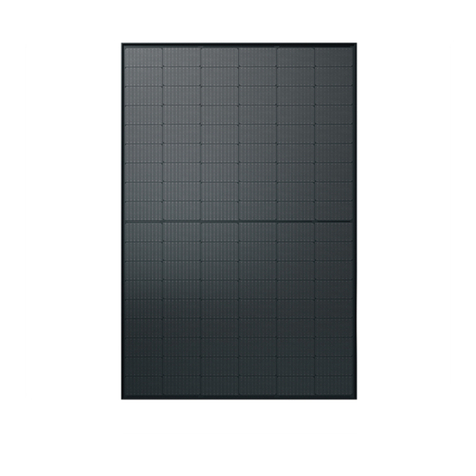
AXITEC 60-CELL User manual

1/12 AXITEC INSTALLATION –USA 170727
Installation Manual
AXITEC SOLAR MODULES

2/12 AXITEC INSTALLATION –USA 170727
Table of Contents
INTRODUCTION.............................................................................................................................................. 3
DISCLAIMER OF LIABILITY............................................................................................................................ 3
GENERAL INFORMATION.............................................................................................................................. 3
SAFETY............................................................................................................................................................ 3
1WARNING AND CAUTION ...................................................................................................................... 4
1.1 WARNING........................................................................................................................................ 4
1.2 AVOID INJURY AND DAMAGES..................................................................................................... 4
1.3 CAUTIONS....................................................................................................................................... 5
2INSTALLATION AND OPERATION......................................................................................................... 5
3MECHANICAL INSTALLATION............................................................................................................... 5
3.1 60-CELL MODULES......................................................................................................................... 6
3.2 72-CELL MODULES......................................................................................................................... 7
3.3 MOUNTING WITH BOLTS............................................................................................................... 8
3.4 MOUNTING WITH CLAMPS............................................................................................................ 9
3.5 GROUNDING................................................................................................................................... 9
4ELECTRICAL INSTALLATION................................................................................................................. 9
4.1 GENERAL WIRING.......................................................................................................................... 9
4.2 MODULE WIRING.......................................................................................................................... 10
4.3 ARRAY WIRING............................................................................................................................. 10
5JUNCTION BOX AND TERMINATION.................................................................................................. 10
6MAINTENANCE ..................................................................................................................................... 11
7SPECIFICATION.................................................................................................................................... 11
7.1 ELECTRICAL SPECIFICATION (Typical)...................................................................................... 11
7.2 GENERAL SPECIFICATION.......................................................................................................... 11

3/12 AXITEC INSTALLATION –USA 170727
INTRODUCTION
Thank you for choosing AXITEC LLC PV modules. With proper operation and maintenance, AXITEC LLC
modules will provide you with clean and renewable solar electricity for years. This manual contains
necessary installation, maintenance and safety information. The word “module” as used in this manual
refers to one or more PV modules. Retain this manual for future reference.
DISCLAIMER OF LIABILITY
AXITEC LLC does not assume responsibility and expressly disclaims liability for any loss, damage, or
expense arising out of, or in any way connected with installation, operation, use, or maintenance by using
this manual. AXITEC LLC assumes no responsibility for any infringement of patents or other rights of third
parties, which may result from use of modules. No license is granted by implication or under any patent or
patent rights. The information in this manual is reliable, but does not constitute an expressed and/or implied
warranty. AXITEC LLC reserves the right to make changes to the product, specifications, or this manual
without prior notice. Without any prior written authorization, AXITEC LLC will not accept any returned
modules.
GENERAL INFORMATION
The installation of solar modules must only be performed by skillful and qualified professionals.
SAFETY
Follow all permission, installation and inspection requirements.
Must contact the appropriate authorities to determine permissions, installation and inspection
requirements to follow that apply to your site and installation before installing modules/system.
Check applicable building codes to ensure that the construction or structure (roof, façade, support,
etc.) where the modules are installed do have enough strength.
Special construction or structures must be required to help provide proper installation support in the
case of modules mounted on roofs.
Both roof construction and module installation design have an effect on the fire resistance of a
building. Improper installation will cause fire hazards. Additional devices such as ground faults,
fuses, and disconnects may also be required.
Do not use different modules in the same mounting system.
Check and follow all safety precautions of other system components.

4/12 AXITEC INSTALLATION –USA 170727
1 WARNING AND CAUTION
1.1 WARNING
All instructions must be read and understood before attempting to install, wire, operate, and/or maintain the
photovoltaic module. When PV modules are exposed to sunlight or other light sources, they generate DC
electrical energy. Contact with electrically active parts of the module such as terminals can result in burns,
sparks, and lethal shock whether the module is connected or disconnected. The shock hazard increases as
modules are connected in parallel, producing higher current, and as modules are connected in series,
producing higher voltage. The installer assumes the risk of all personal injury or property damage that might
occur during installation and handling of modules.
1.2 AVOID INJURY AND DAMAGES
Cover the entire front and back surface of the PV modules with a dense, opaque material such as a
cardboard box.
Do not step or stand on a module.
Work only in dry conditions, with dry modules and tools.
Do not break the glass surfaces of modules.
Do not drop a module.
Do not allow children and unauthorized persons near the installation site or storage area of
modules.
All modules have been complete grounding to earth with electrical insulation.
Do not open the cover of the junction box.
Do not disassemble the module, or remove any part installed by the manufacturer.
Wear suitable protection (gloves, clothes, etc.) to prevent direct contact with 30V DC or greater.
Do not carry a module by its wires or junction box.
Carry a module by its frame with two or more people.
Wear non-slip gloves.
Do not drop or place heavy items on the surfaces of a module such as tools or other module.
Check that all other system components (inverters, wires, racks, balance of system materials, etc.)
are mechanically and electrically compatible before installation.
Do not install the module where flammable gases or vapors are present.
Never leave a module unsupported or unsecured.
Do not use or install the broken or damaged modules.
Do not artificially concentrate sunlight on a module.
Do not touch the junction box terminals.
Do not change the wiring of bypass diodes.

5/12 AXITEC INSTALLATION –USA 170727
1.3 CAUTIONS
Use a module for its intended purpose only.
Do not treat any portion of the module with paint or adhesives, to avoid damage to the module,
inoperable conditions, or reducing the module’s functionality.
Careful attention to the design of the PV system and electrical capacity of system components is
required (especially the inverter) for the reason that this module may generate more than 120% of
its’ STC rated power (Pmax).
This additional power depends upon the level of incident light irradiance (Aledo) available to the
backside of the module, and can be increased or decreased depending upon site characteristics
and installation design.
Please don’t uses artificially concentrate sunlight on the modules.
2 INSTALLATION AND OPERATION
Systems must be installed by qualified and experienced personnel only.
Do not step on the module. Although AXITEC LLC modules are quite rugged, the glass may be
broken (and the module will no longer work properly) if it is dropped or hit by tools or other objects.
Sunlight shall not be concentrated on the module.
The module frames is made of anodized aluminum, and therefore corrosion can occur if the module
is placed in a salt water environment with contact to a rack of an- other type of metal (Electrolytic
Corrosion). If required, PVC or stainless steel washers can be placed between the solar module
frame and support structure to prevent this type of corrosion.
Any module support structures that are to be used to support AXITEC LLC solar module must be
wind rated and approved for use by the appropriate local and civil codes prior to installation.
3 MECHANICAL INSTALLATION
There are different ways to attach the solar module. The solar module of AXITEC LLC can be attached and
installed with mounting holes or clamps. The module can be installed in both landscape and portrait modes.
Figure 1 shows the different mounting options with the appropriate snow loads.

6/12 AXITEC INSTALLATION –USA 170727
3.1 60-CELL MODULES
Figure 1
A distance: 7.87 inch (200 mm)
B clamping zone: 7.87 inch (200 mm
C clamping zone: 11.81 inch (300 mm)
D clamping zone: 7.87 inch (200 mm)

7/12 AXITEC INSTALLATION –USA 170727
3.2 72-CELL MODULES
A distance: 11.42 inch (290 mm)
B clamping zone: 7.87 inch (200 mm)

8/12 AXITEC INSTALLATION –USA 170727
3.3 MOUNTING WITH BOLTS
Module can be mounted at 4 (four) or 8 (eight) symmetrical quarter points within the shaded areas shown in
Figure 1. This method offers a maximum loading of 113 PSF (5,400N/m²) in a static state on the module
surface. The frame of each module has eight (8) 0.26 x 0.39 inch (6.5mm x 10 mm) mounting holes. The
four holes of the module (shaded areas Figure 1) are most often used for mounting. These are used to
secure the modules to the supporting structure. The standoff method or the rack method is recommended in
case the modules will be mounted on the roof of a building. The modules are supported parallel to the
surface of the building roof. To prevent wiring damage and to allow air to circulate behind the module,
clearance between the module frames and surface of the roof is required. The standoff minimum height is
3.9 inch (about 100 mm) (refer to Figure 2). If other mounting means are employed, this may affect the
listing for fire class ratings.
Figure 2
The solar module frame must be attached to a support structure using 1/4” or M6 stainless steel hardware
in a minimum of four (4) places symmetrical on the solar module. The stainless hardware used for securing
the module frame should be secured with an applied torque of 6 foot-pounds (8 Newton-meters). Refer to
Figure 3.
Self-tapping Screw (M6)
Washer (M6)
Screw (M6)
Nut M6

9/12 AXITEC INSTALLATION –USA 170727
3.4 MOUNTING WITH CLAMPS
It is the installer’s responsibility to ensure that the clamps used to attach the module are strong enough.
Figure 4 shows the module mounted with clamp.
Figure 4
The clamps must not be in contact with the front glass or deform the frame in any way. Avoid shading
effects from the clamps and mounting system.
3.5 GROUNDING
All module frames and mounting racks must be properly grounded in accordance with the appropriate
respective National Electrical Code.
Proper grounding is achieved by bounding the module frame and all metallic structural members
together continuously using a suitable grounding conductor. The grounding conductor or strap may be
copper, copper alloy or other material acceptable for use as an electrical conductor per respective
National Electrical Codes. The grounding conductor must make a connection to earth using a suitable
earth ground electrode.
4 ELECTRICAL INSTALLATION
4.1 GENERAL WIRING
All wiring should be done in accordance with applicable local electrical codes.
Clamp
Module
frame

10/12 AXITEC INSTALLATION –USA 170727
A qualified, licensed professional must do all wiring.
Wiring should be protected to help ensure personal safety and to prevent its damage.
All modules connected in series should be of the same model number and/or type.
Suitable measures will be required to protect against overcurrent (e.g. line fuses) for parallel connection
of modules. Care must be taken to avoid exceeding the given load with regard to the IR reverse current,
see datasheet of module.
4.2 MODULE WIRING
The maximum system voltage is 1000 V DC according to UL standards.
The maximum number of series connected modules depends on system design, the type of inverter
used and environmental conditions.
These modules contain factory installed bypass diodes. If these modules are incorrectly connected to
each other, the bypass diodes, cable, or junction box may be damaged.
For field connections, use minimum No. 12 AWG copper wires insulated for a minimum of 90°C.
The size, type, and temperature rating of the conductors to be used; Size: 12AWG; Type: Tinned fine
copper strands, according to VDE 0295/IEC60228, class 5; Temperature rating: -40°C up to +125°C
4.3 ARRAY WIRING
Use copper wire only (Cu only) that is sunlight resistant and is insulated to withstand the maximum
possible system open circuit voltage.
For use with non-metallic wiring systems only.
For field connections, use minimum No. 12 AWG copper wires insulated for a minimum of 90°C
The size, type, and temperature rating of the conductors to be used; Size: 12AWG; Type: Tinned fine
copper strands, according to VDE 0295/IEC60228, class 5; Temperature rating: -40°C up to +125°C
The minimum and maximum cable diameters: min. 12 AWG (4mm²), max. 10AWG (6mm²)
Check local codes for requirements.
5 JUNCTION BOX AND TERMINATION
Modules equipped with one junction box contain terminals for both positive and negative polarity, and
bypass diodes.
One terminal is dedicated to each polarity, with the polarity symbols engraved onto the body of the
junction box.
To ensure reliable electric connection and to prevent possible intrusion of humidity, the connectors have
to be mated and locked together until a click can be heard.

11/12 AXITEC INSTALLATION –USA 170727
6 MAINTENANCE
When the module’s front or back surface becomes dirty, power output is reduced.
It is recommended to clean the front surface of the module with clean water and a mild, non-abrasive
sponge or cloth for cleaning.
It is also recommended to inspect the electrical and mechanical connections annually.
7 SPECIFICATION
7.1 ELECTRICAL SPECIFICATION (Typical)
The electrical characteristics are within ±3 percent of the indicated values of ISC, VOC, and Pmax
under standard test conditions (irradiance of 100 mW/cm2, AM 1.5 spectrum, and a cell temperature of
25°C (77°F))
Under normal conditions, a solar module is likely to experience conditions that produce more current
and/or voltage than reported at standard test conditions.
Accordingly, the values of ISC and VOC marked on this module should be multiplied by a factor of 1.25
when determining component voltage ratings, conductor ampacity, fuse sizes, and size of controls
connected to the PV output.
Refer to Section 690-8 of the National Electrical Code for an additional multiplying factor of 125 percent
(80 percent derating) which may be applicable.
7.2 GENERAL SPECIFICATION
Axitec LLC reserves the right to make unannounced alterations to the design and/or technical specifications
of its solar modules at any time. Therefore, only the datasheet current at the time of manufacture is
definitive. It is therefore expressly recommended to ensure that the datasheets on hand represent the
current status before placing an order. When performing assembly or other work on the solar modules, the
datasheets and user information current at the time of manufacture of the relevant module are to be used
for reference. The contents of older or newer documents may be incorrect due to interim product changes.

12/12 AXITEC INSTALLATION –USA 170727
AXITEC, LLC
1819 Underwood BLVD, Suite 5
Delran, New Jersey 08075
United States of America
www.axitecsolar.us
This document is subject to change without notice.
This manual suits for next models
1
Table of contents
Other AXITEC Solar Panel manuals
Popular Solar Panel manuals by other brands

CSG PVTech
CSG PVTech CSG270M2-35/1956x992 series installation manual

Xantrex
Xantrex 784-9345-01 installation guide

SUNFLOWER
SUNFLOWER SFB-AL Series installation manual

Phaesun
Phaesun Solar Modul Ascent 45W Safety and installation manual

Suntactics
Suntactics sCharger-5 manual

Phono Solar
Phono Solar F Type module installation manual