3B SCIENTIFIC 1000539 User manual

3B SCIENTIFIC®PHYSICS
1
3B Netlog™
1000539 (115 V, 50/60 Hz)
1000540 (230 V, 50/60 Hz)
Instruction manual
06/14 MEC
1. Safety instructions
To guarantee the safe functioning of the
3B NETlog™ equipment, it is necessary to
abide by the following instructions:
•Do not connect the 3B NETlog™ device to
a voltage in excess of ±20V or current in
excess of ±2A.
•Make sure the 3B NETlog™ device does
not come into contact with water.
•The 3B NETlog™ device should not be
exposed to temperatures above 80°C.
The operating voltage input is protected
against polarity reversal. However, it is not
protected against excess voltage.
•Do not apply voltage in excess of 4.5V to
the operating voltage input.
2. Scope of delivery
1 3B NETlog™ device
1 Power supply unit (4.5V DC, 300mA)
1 USB cable
1 Installation CD
3. Introduction
3B NETlog™ is a multimedia data acquisition
and evaluation system for current and voltage
measurements and for measurements using
sensors. The system can be used with or with-
out being connected to a computer. With the
accompanying 3B NETlab™ software, meas-
urements can be conducted with arbitrarily
chosen parameters as well as in prepared
experiments. The prepared experiments take
the user through an interactive experimental
environment where the measurement parame-
ters have already been defined. When used
within a network, the teacher and students can
mutually monitor their results.
Without being connected to a computer, the
3B NETlog™ device can be used as a digital
multimeter for current and voltage measure-
ments. Combined with different sensors, the
3B NETlog™ equipment can also be used as a
handheld unit with automatic sensor recogni-
tion.

2
4. Technical specifications
4.1 Analogue inputs
Voltage inputs (channels A and B):
Measuring equipment: 2 differential amplifiers
Measuring range: ±200mV, ±2V, ±20V
Surge voltage protection: Max. ±40V
Connections: 4-mm safety sockets
Current input (channel A):
Measuring range: ±200mA, ±2A
Excess current protection:Max. ±2.5A
Connections: 4-mm safety sockets
Sensor inputs (channels A and B):
Sensor type: Analogue
Sensor identification: Automatic
Sensor connections: 8-pin mini DIN sockets
Sampling: Continuous
Sampling rate: 50k samples/s
Resolution: 12 bit
4.2 Analogue outputs (channels A and B)
Reference point (earth): Common
Measuring range: ± 5V
Connections: 4-mm safety sockets
and 8-pin mini DIN
sockets
Sampling rate: 10 kSamples/s
Resolution: 12 bit
4.3 Digital inputs
Channels: 4 (separated into 2
TTL inputs, one of
which is a high-speed
time input, plus 2 in-
puts via optocoupler)
Sampling rate: 50k samples/s
100k samples/s (high-
speed time input)
Connection: 8-pin mini DIN socket
4.4 Digital outputs
Channels: 6
Signal: TTL
Connection: 8-pin mini DIN socket
4.5 Additional data
Computer connection: USB
Internal data memory: 128k
Display: 64 x 122 matrix for
measurements and
units
Power supply: 4.5 V DC / 300 mA or
3 batteries (AA, LR6 or
AM3); owing to their
longer battery life, use
of alkaline batteries is
recommended.
Dimensions: 21 x 8 x 4 cm3approx.
Weight: 400g approx. (includ-
ing batteries)
5. Description
5.1 Components
1 Display
2 Operating controls
3 Current input for chan-
nel A
4 Voltage outputs for
channels A and B
5 Voltage inputs for
channels A and B
6 Digital outputs
7 Digital inputs
8 Analogue outputs A
and B
9 Analogue inputs A and
B

3
10 Recessed socket for
power supply unit
11 USB connection
12 Mount
13 Battery compartment
14 Fuse
5.2 Operating controls
The operating controls of the 3B NETlog™ unit
consist of five multi-function buttons for opera-
tion without connection to a PC.
On/Off button
•Switching the device on and off (keep the
button pressed for approx. 2 seconds to
switch off the device)
•Switching the display lighting on and off
(briefly press the button)
Date/Time button ↵
•Switching on the battery and temperature
displays
•Switching on the time display
•Switching on the date display
•Selection of operating mode (manual or
automatic)
•Confirming the display →
Store button ↓
•Communication to data logger
•Scrolling down the menu
•Selecting Yes or No
•Confirming the display ↓
Rate button ↑
•Selection of sampling rate
•Scrolling up within the menu
•Selecting Yes or No
•Confirming the display ↑
Channel button ←
•Selection of measurement parameters for
channels A and B
•Changing between fields while setting the
time and date
•Return to previous menu
5.3 Measurement parameters
Name Significance
VdcA DC voltage on channel A
VacA AC voltage on channel A
Idc DC current on channel A
Iac AC current on channel A
VdcB DC voltage on channel B
VacB AC voltage on channel B
Bin Binary representation
5.4 Connection of sensors
Connected sensors are automatically detected
by the 3B NETlog™ device. The following
status message appears on the display:
PROBE DETECT…. Subsequently, the meas-
urement and the unit corresponding to the
connected sensor are displayed.
6. Commissioning
6.1 Operating with the power supply unit
•Insert the recessed plug of the power sup-
ply unit into the recessed socket of the
3B NETlog™ device.
•Connect the power supply unit to the
mains.
•If necessary, press the On/Off button.
6.2 Operating with batteries
•Open the lid of the battery compartment
and insert three batteries (AA, LR6 or
AM3) while carefully observing the polarity
(batteries not included).
•If necessary, press the On/Off button.

4
7. Operating with a computer and
3B NETlab™ software
In order to operate the 3B NETlog™ equip-
ment with a computer, the 3B NETlab™ soft-
ware and a computer with the following system
requirements are necessary:
•Windows XP and Microsoft Internet Ex-
plorer up to version 8
•Windows 7 (32-bit and 64-bit) and Micro-
soft Internet Explorer up to 11 or higher
•Windows 8.1 (32-bit und 64-bit) and Micro-
soft Internet Explorer up to 11 or higher
•32-bit (x86) or 64-bit (x64) processor with a
speed of at least 1 GHz
•At least 1 GB RAM
•At least 500 MB hard disc memory
Note when operating via a computer,
never press the buttons on the
3B NETlogTM console.
7.1 Driver installation
Before installing the 3B NETlab™ software, it
is important to install the USB driver:
•Insert the installation CD into the CD-ROM
drive of the computer.
•Connect 3B NETlog™ to the computer via
the USB cable.
The computer reports that it has detected a
new hardware.
Windows XP:
•Do not activate Windows Update.
•Select “Install software from specified loca-
tion”.
•Under “Browse”, specify the location of the
driver on the CD.
•A hardware message will state that the
software has failed to pass the Windows
Logo Test. You should nevertheless click
“Proceed with installation”.
Windows 7 and 8.1:
The operating system automatically installs a
driver which is packaged with Windows. How-
ever, this driver is not used with 3B NETlog™.
The correct driver therefore needs to be in-
stalled manually as per the following instruc-
tions:
•Open the hardware manager under Control
Panel -> Hardware and Sound -> Hard-
ware Manager.
•Double click "USB Controller" in the hard-
ware manager.
•Double click "USB Serial Converter".
•Click Drivers -> Update Driver.
•A small window will open so that you can
search for the driver software. Click "Find
driver software on this computer" in the
window.
•Click the "Browse…" button and select the
path for the driver.
•Follow the instructions to install the driver.
As an alternative, the folder containing the
driver file can be copied directly onto the com-
puter from the CD and can be installed from
the hard disk.
Exception:
If the software for the CCD linear
camera (1013311) is already installed on your
computer, carry out the following instructions:
•Connect 3B NETlog™ to the computer via
the USB cable.
The computer will not report that a new hard-
ware has been detected.
•Insert the installation CD into the CD-ROM
drive of the computer.
Windows XP:
•System control panel -> System -> Hard-
ware -> open Device manager.
•Double-click on USB controller.
•Double-click “ULICE USB Product”.
•Click Driver -> Update driver. (The hard-
ware assistant will start.)
•Do not activate Windows Update.
•Select “Install software from specific
source”.
•Select “Do not search. Autodetect driver”.
•Select “Drive” and then “Search” to estab-
lish the path to the driver.
•Click “Yes” to confirm that the file should
be overwritten.
•Click “Proceed with installation” when the
hardware message states that the software
has failed to pass the Windows Logo Test.
Windows 7 and 8.1:
•Open the hardware manager under Control
Panel -> Hardware and Sound -> Hard-
ware Manager.
•Double click "USB Controller" in the hard-
ware manager.
•Double click “ULICE USB Product”.
•Click Drivers -> Update Driver.

5
•A small window will open so that you can
search for the driver software. Click "Find
driver software on this computer" in the
window.
•Click "Select from a list of device drivers on
this computer".
•Click the "Medium…" button.
•Click the "Browse…" button and select the
path for the driver.
•Click “Yes” to confirm that the file should
be overwritten.
7.2 Software installation
Note on installing the software
For this software, please refer to the installa-
tion instructions available in the 3B NETlab™
software manual.
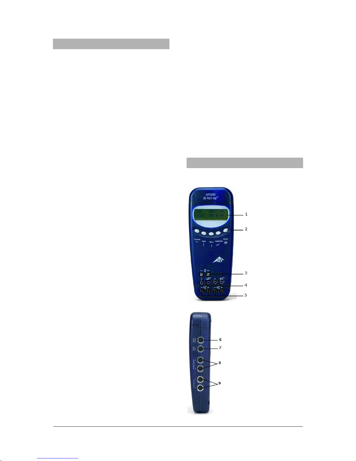
8. Operating without a computer
Operating a 3B NETlog™ device without a
computer is achieved by using the buttons on
the operating panel. The functions of these
buttons may change according to the operation
being undertaken.
Note: a menu selection can be can-
celled at any time by using the
Channel
←
button.
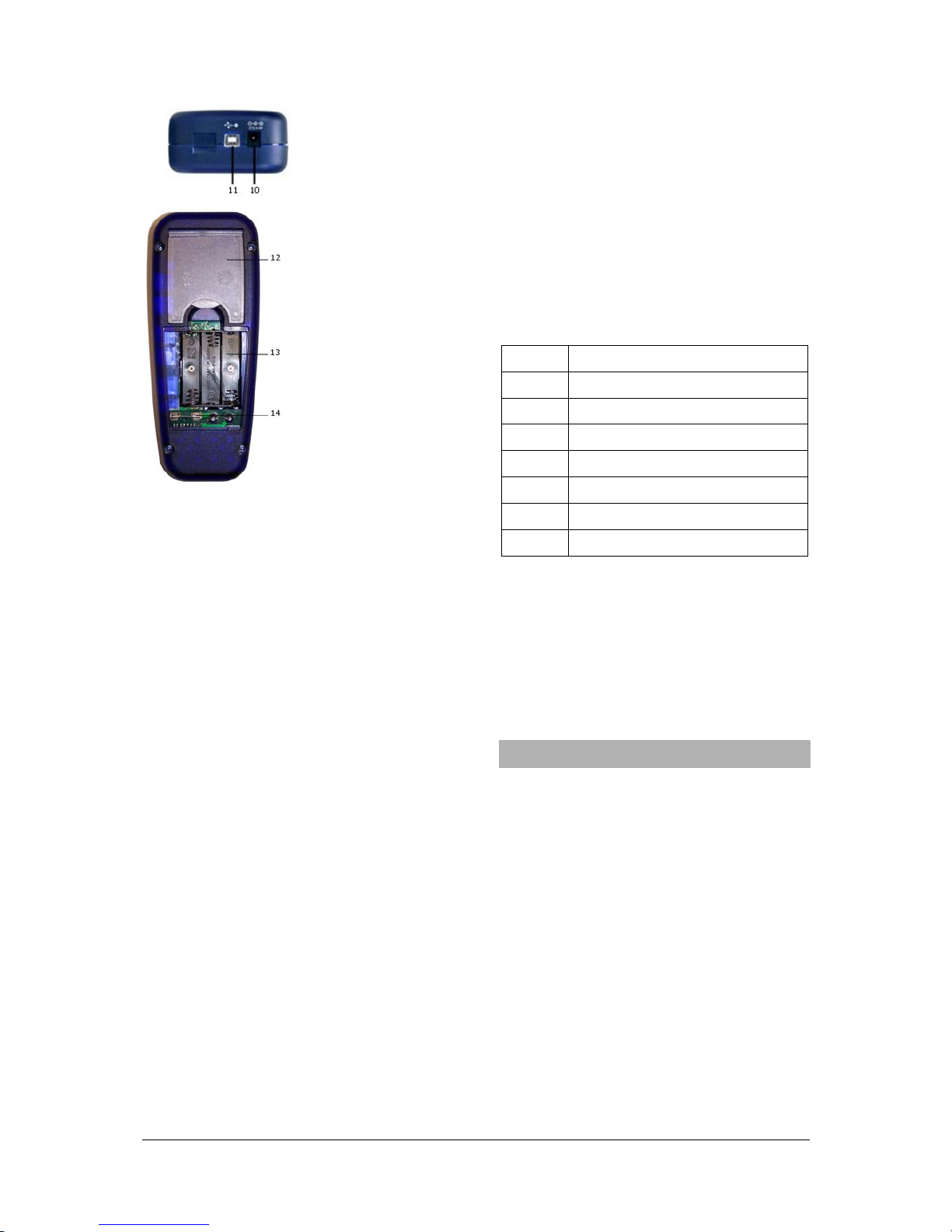
8.1 Battery level and temperature display
•Switch on the 3B NETlog™ device by
pressing the On/Off button.
•Press the Date/Time ↵button.
The following should appear on the display:
e.g.: BATTERY: 100%
TEMP.: 22.0°C
8.2 Setting the time
•Switch on the 3B NETlog™ device by
pressing the On/Off button.
•Press the Date/Time ↵ button twice (the
time field will appear on the display).
•Press the Store ↓button (the input field for
SET TIME will appear on the display).
•Specify the desired time in the input field
by pressing the Rate ↑or the Store ↓but-
ton and use the Channel ←button to skip
between the hours, minutes and seconds
fields.
•Confirm by pressing the Date/Time ↵but-
ton.
8.3 Setting the date
•Switch on the 3B NETlog™ device by
pressing the On/Off button.
•Press the Date/Time ↵three times (the
date field will appear on the display).
•Press the Store ↓button (the input field for
SET DATE will appear on the display).
•Specify the desired date in the input field
by pressing the Rate ↑or Store ↓button
and use the Channel ←button to skip be-
tween the year, month and day fields.
•Confirm by pressing the Date/Time ↵but-
ton.
8.4 Application as a handheld device for
measuring current and voltage
•Set up the 3B NETlog™ equipment.
•Connect the voltage/current input of chan-
nel A or B, as desired.
•If necessary, disconnect any sensor which
might be connected to the same channel.
Setting and selecting measurement parame-
ters:
•Press the Channel ←button (the menu
DISPLAY SIGNAL 1 will appear on the
display).
•Select the desired measurement parame-
ter with the Rate ↑or Store ↓button.
•Select the mode of operation with the
Date/Time ↵button (the menu RANGE
SIGNAL 1 will appear on the display).
•Select the desired mode of operation with
the Rate ↑or Store ↓button.
•Confirm this selection with the Date/Time ↵
button (the menu DISPLAY SIGNAL 2 will
appear on the display).
•Select the desired measurement parame-
ter with the Rate ↑or Store ↓button.
•Select the desired mode of operation with
the Rate ↑ or Store ↓button.
•Confirm the selection with the
Date/Time ↵ button (a dot will appear in
front of the respective measurement pa-
rameter when operating manually).
The 3B NETlog™ device is ready to conduct
measurements.
8.5 Application as a handheld measuring
device with sensors
•Set up the 3B NETlog™ equipment.
•Connect the sensor to the relevant input
and remove the connections of the 4-mm
sockets from the same channel.

6
After the automatic sensor detection PROBE
DETECT… has been completed, the
3B NETlog™ equipment is ready to conduct
measurements.
8.6 Setting the sampling rate
•Press the Rate ↑button (the options list for
SAMPLE RATE will appear).
•Select the desired sampling rate with the
Rate ↑or Store ↓button.
•Press the Date/Time ↵button (the settings
STORE ANALOGUE INPUT 1, STORE
ANALOGUE INPUT 2 and STORE BI-
NARY INPUTS will appear in succession).
•Select YES or NO for each setting with the
Rate ↑ or Store ↓button and confirm with
the Date/Time ↵button (the subsequent
setting will appear after each confirmation).
8.7 Data logger
In data logger mode, the 3B NETlog™ equip-
ment records the data with a pre-selected
sampling rate and saves it internally. After
completing a measurement, the data can be
transferred onto a computer for evaluation.
Calling up data logger mode:
•Press the Store ↓button (STORE will ap-
pear with →STARTor ↑CLEAR →
START displayed).
Starting data logger:
When the display shows →START:
•Start recording data with the Date/Time ↵
button (“BUSY →STOP” will appear in the
display and the measurement begins).
Stopping the data logger:
When the display shows →STOP:
•Stop recording data by pressing the
Date/Time ↵button (↑CLEAR →START
will appear in the display).
Clearing data logger:
When the display shows ↑CLEAR:
•Press the Rate ↑button (MEM.CLEAR? →
YES will appear in the display).
•Confirm by pressing the Date/Time ↵but-
ton.
Exiting data logger mode:
When the display shows ↑CLEAR →START:
•Press the Channel ←button.
9. 3B NETdata transfer software
Data stored in the 3B NETlog™ memory can
be retrieved and saved as text files with the
help of the 3B NETdata software. In addition,
the software also provides the capability to set
modes of measurement and measurement
parameters.
Note: Only one interface 3B NETlog™
may be connected to the com
p
ute
r
when using the software 3B NETdata.
9.1 Installation of the driver
Before installing the 3B NETlab™ software it is
necessary to install a USB driver. Proceed as
described in 7.1.
9.2 Software installation
•Run the installation program "start.exe" as
administrator and follow the instructions on
the screen.
9.3 Control elements
The control interface consists of three dialogs
that can be brought to the front by clicking the
relevant tab. The “Read Data” tab is used for
transferring measurement data from the
3B NETlog™memory, the “Device Set-up” tab
is used for setting the measurement parame-
ters and mode of measurement for the
3B NETlog™ device and the “Update firmware”
tab is for updating the firmware of
3B NETlog™, see description in chapter 10.
Read Data
•Read: reads all data available in the mem-
ory of the device and presents an overview
of the measurements in a list.
•Abort: aborts the reading operation.
•Status: displays the current status.
•Time elapsed: shows the time that has
elapsed since the beginning of the read
operation.
•Time remaining: shows the approximate
time remaining for the read operation.
•Options: the following settings can be
made here:
•Decimal separator: sets the decimal
separator which is used in exported files.
•Date/Time format: specifies the time and
date format which is used in exported
measurement files.
•List (left): shows the acquired data.
•List (right): additional selection of columns
which can be added to the exported files.

7
•Index: serial number, beginning with 1.
•Absolute date/time: date and time when
the measurement/set of measurements
was recorded.
•Relative time [s]: elapsed time in sec-
onds, from the beginning of the measure-
ment to the recording of the current meas-
urement/set of measurements.
•Save selected data to files: converts the
measurements selected in the left-hand list
into text files (separated by tab charac-
ters). A file name is requested for each
measurement. The preset file names in-
clude date, time, measurement values and
sampling rate and can be adopted without
any changes.
•Quit exits the program.
Device Set-up
•Vdc/Vac/(Idc/Iac): selects the measuring
mode for the aforementioned analogue in-
put (Vdc: DC voltage/Vac: AC voltage/Idc:
DC current/Iac: AC current).
•Range slider (200mV-20V/200mA-2A):
selects the measurement range for the
above-mentioned analogue input.
•Auto Range: if this control box is acti-
vated, the measuring range is automati-
cally adjusted by the device during the
measurement.
•Store: determines whether data from the
aforementioned input should be stored.
•Sampling rate slider: this sets the sam-
pling rate for the measurements. Fre-
quency is displayed in the field f=, and the
corresponding cycle duration is displayed
in the field T=.
•Apply settings: writes the selected set-
tings to the device.
•Clear memory: clears the entire memory
of the instrument.
•Quit: exits the program.
9.4 Reading and saving measurement data
Reading and saving measured data with the
3B NETlog™ equipment:
•Connect the 3B NETlog™ equipment to a
computer via USB cable.
•Start 3BNETdata and click on the tab
“Read Data”.
•Press Read and wait till the progress bar
reaches 100%.
•Select the measurements you wish to be
saved from the list on the left.
•Select columns that are to be written next
to the data.
•Click Save selected data to files
•Enter a file name for each measurement,
or accept the default name.
•For further processing of the saved data,
use spreadsheet or data analysis pro-
grams.
10. Update Firmware
•In the 3B NETdata software, click “Update
firmware” tab.
•Follow the instructions in the left-hand
section of the software window and click
“Start” in the options box.
The current version of the firmware will now be
installed automatically. As an alternative, use
“Browse” in the options’ box to search and
install older firmware versions.
11. Format of exported files
Exported files have the following format (the words shown here between the delimiters <> are simply
placeholders for actual data. Entries are separated by tab characters. Depending on the settings,
some columns may be omitted):
# <Date> <Time>, <Inputs/Measurement modes>, <Sampling rate>, <Number of
measurement records>
Index (tab) Absolute date/time (tab) Relative time (tab) <Quantity at ana-
logue input A>[<Unit for analogue input A>] (tab) <Quantity at analogue in-
put B>[<Unit for analogue input B>] (tab) Dig A (tab) Dig B (tab) Dig C
(tab) Dig D(return)

3B Scientific GmbH • Rudorffweg 8 • 21031 Hamburg • Germany • www.3bscientific.com
Subject to technical modifications
© Copyright 2014 3B Scientific GmbH
1(tab)<Absolute date/time of the first measurement record>(tab)<Relative
time of the first measurement record>(tab)<Value 1 of analogue input
A>(tab)<Value 1 of analogue input B>(tab)<Value 1 of digital input
C>(tab)<Value 1 of digital input D>(return)
2(tab)<Absolute(s) Date/Time of the second measurement data set
>(tab)<Relative time of the second measurement data set>(tab)<Value 2 of
analogue input A>(tab)<Value 2 of analogue input B>(tab)<Value 2 of digital
input C>(tab)<Value 2 of digital input D>(return)
etc.
12. Faults and possible remedies
Fault Cause Remedy
The
3B NET-
log™ device
cannot be
switched on
when oper-
ating with
batteries
The batteries
are worn out.
Replace with
new batteries
or use the
power supply
unit.
When the
“Test” button
in the
3B NET-
lab™ soft-
ware is acti-
vated, the
“Connected”
message
does not
appear.
The 3B NET-
log™ device
is not
switched on.
There is no
connection
between the
computer and
the
3B NETlog™
equipment.
Switch on the
3B NETlog™
device.
Check the con-
nection be-
tween the com-
puter and
3B NETlog™
device. Press
“Test” again
and, if neces-
sary, refresh
by pressing F5.
13. Support
If you have any queries and/or suggestions,
please feel free to contact our support team:
Email: [email protected]
Internet: http://www.3bnetlog.com/
14. The CE marking
3B NETlog™ conforms to the requirements of
these EU specifications
•EN 61010-1: Protoype-tested
•EN 61326-1: Tested for noise im-
munity and interference
Conformity with EU guidelines is indicated by
the CE marking on the device.
15. Licence
3B Netlog™ and 3B Netlab™ are registered
trademarks of 3B Scientific GmbH in Germany
and other countries.
The 3B Netlab™ computer program is pro-
tected by worldwide copyright. It may be used
exclusively for educational purposes in schools
and educational institutions, including prepara-
tory purposes at home. The fabrication of cop-
ies, unauthorised application or unauthorised
sale is strictly prohibited.
16. Care, maintenance, disposal
•Before cleaning the equipment, disconnect
it from its power supply.
•Use a soft, damp cloth to clean it.
•The packaging should be
disposed of at local recy-
cling points.
•Should you need to dis-
pose of the equipment it-
self, never throw it away in
normal domestic waste.
Local regulations for the
disposal of electrical
equipment will apply.
•Do not dispose of the batteries in the regu-
lar household garbage. Follow the local
regulations (In Germany: BattG; EU:
2006/66/EG).
This manual suits for next models
2
Other 3B SCIENTIFIC Measuring Instrument manuals
Popular Measuring Instrument manuals by other brands

Omntec
Omntec PROTEUS B installation manual

Digatron
Digatron DT-31SN operating instructions

Process Sensors
Process Sensors MCT466-QC User guide manual

Gamatronic
Gamatronic GMAC-5 user guide

MADDALENA
MADDALENA ElecTo Bulk installation instructions

LaserLiner
LaserLiner AutoCross-Laser 360 PowerBright operating instructions