Copyright ©2019 by 3Built LLC 9/30/19 Firmware ver:6.1.19
DEFINITIONS
OEM - Original Equipment Manufacturer. This is any component that the vehicle originally came equipped with from the
factory.
RES - 3Built’s Remote Engine Shut-off kits
Normally-open - means that the switch is open (no connection) when the RES is in the unlocked mode. This connection type is
typically used for ground type OEM RUN/STOP switches.
Normally-closed - means that the switch is closed (connected) when the RES is in the unlocked mode. This connection type is
typically used on positive voltage type OEM Run/Stop switches.
INSTALLATION
1) Charge the Transmitter by plugging it in to a USB charger (5 volts). The cable is a USB to mini-USB. With the power switch off,
you will see a small red or blue light towards the bottom of the Transmitter (small window) while charging. The included lithium
battery is designed for hundreds of charge cycles. It can be replaced, if necessary, with another lithium-ion 18500 size battery.
Blue LED = fully charged ; Red LED = charging
2) Find a suitable place to mount the Receiver. Position it so that it will stay dry and will not be damaged in case of an accident.
3) Attach the Red Wire on the Receiver to 12 volts DC power supply. We recommend that you use a fuse if connecting directly to a
battery or un-fused power wire. Improperly mounted wires can become damaged and short to the frame causing damage to the
vehicle and/or driver. Damage may include high heat and/or fire.
4) Attach the Black Wire to ground.
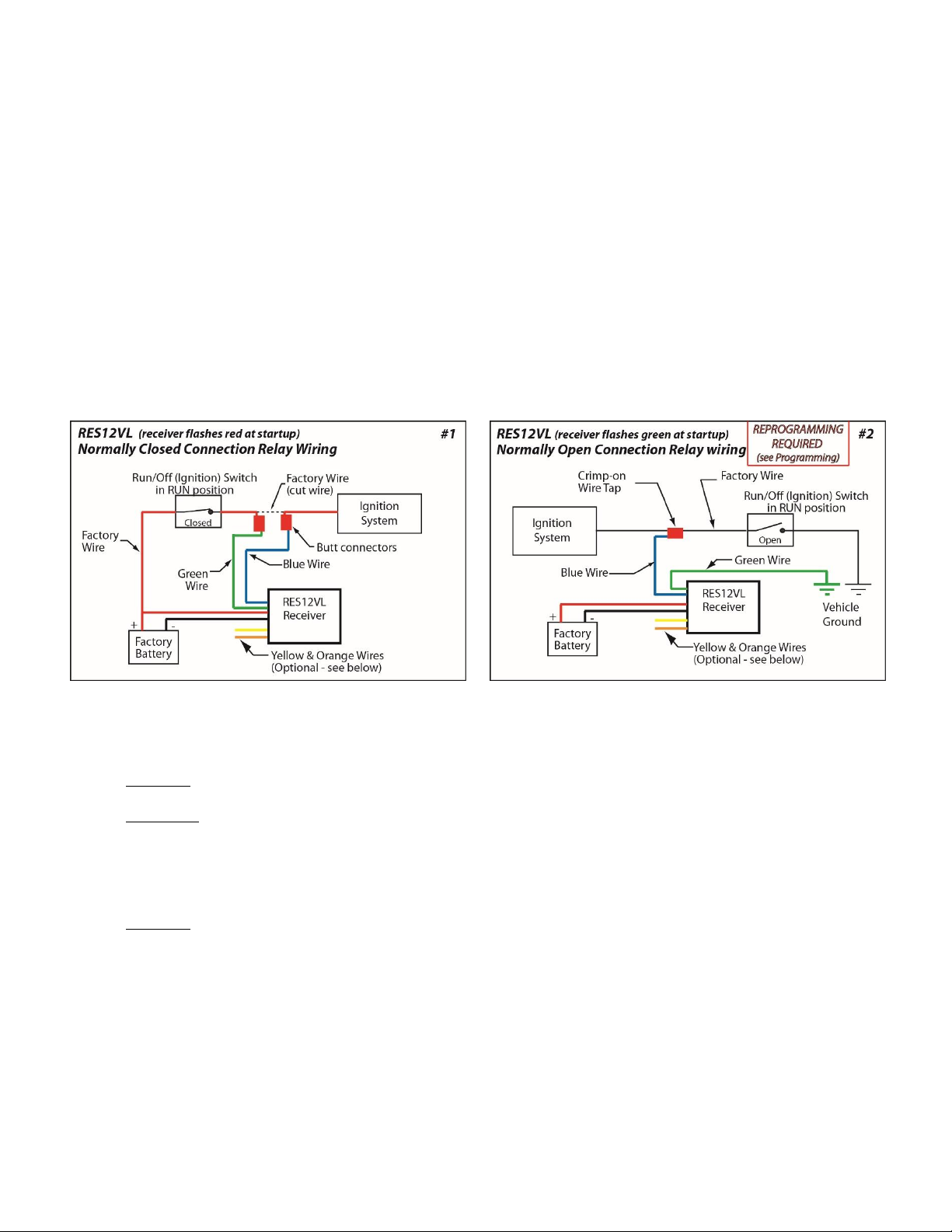
5) Choose either Normally Open or Normally Closed connection type.
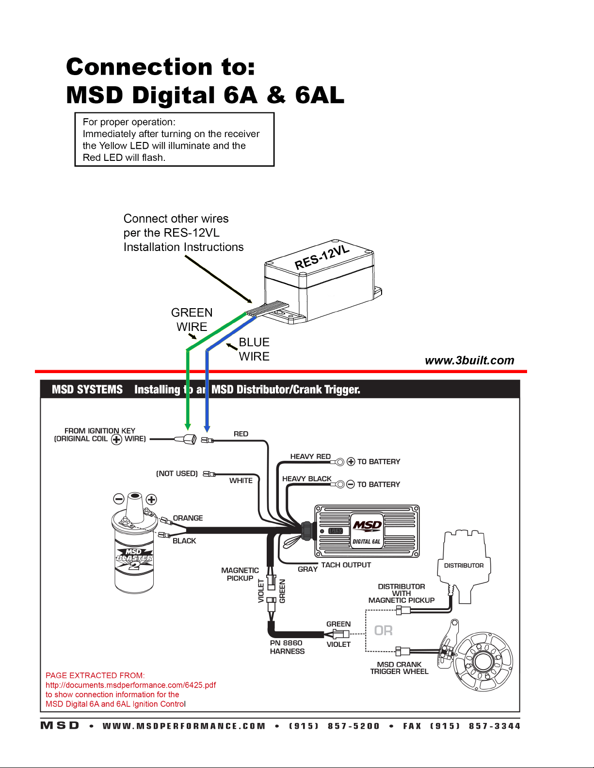
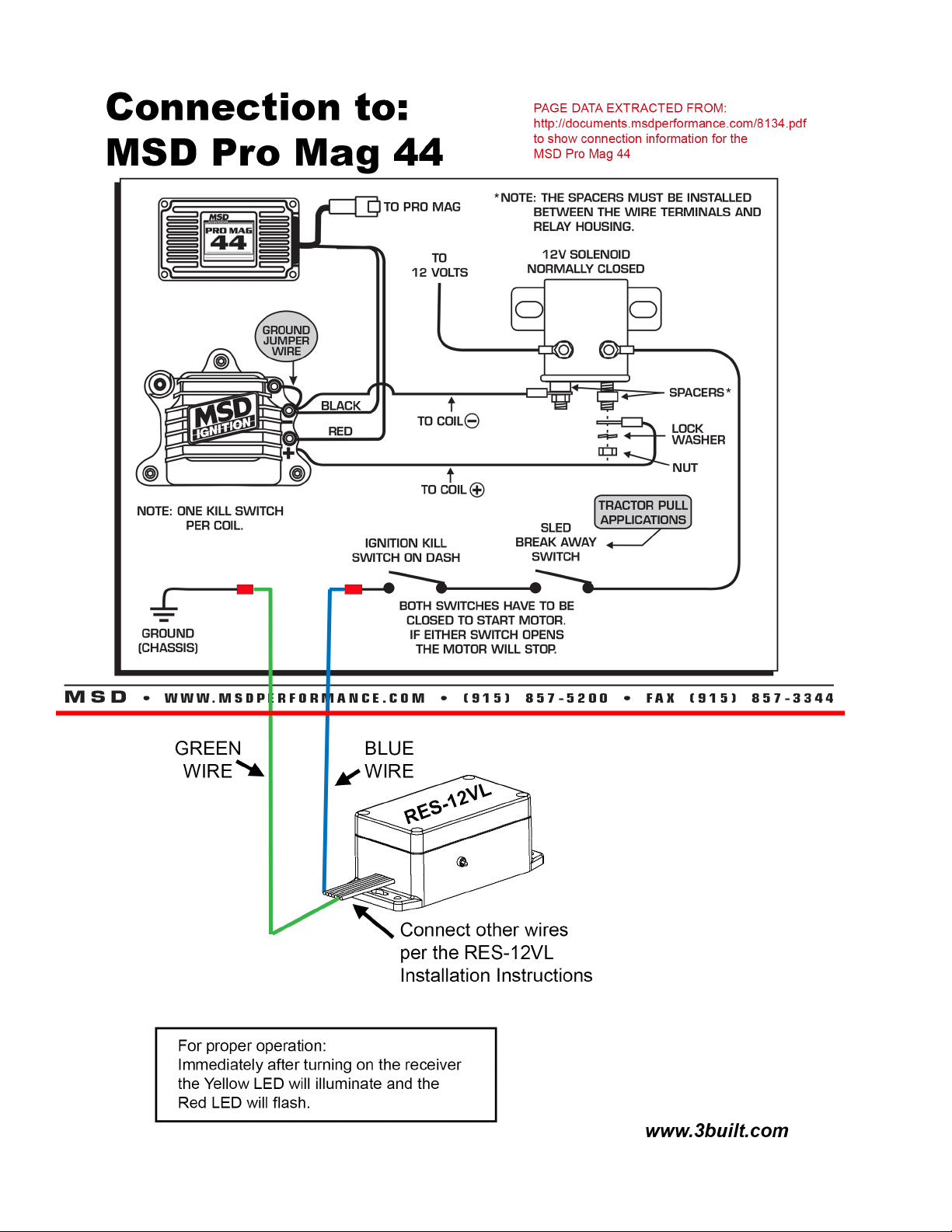
a. Normally Closed Connection for Relay (8-amp max.) [diagram #1] (Default state)
Typical for MSD 6, MSD 7, and MSD Pro Mag 44
This is used typically when an ignition system needs to be powered from the battery. It is very important to cut the correct
wire for proper operation. Incorrect wiring can damage the CDI or other electrical component. Use caution and consult a
professional if unsure.
Blue Wire –Identify the power wire from the OEM Run/Stop switch to the CDI. Cut the wire and attach the Blue Wire to
one end of the cut wire
Green Wire –Attach the Green Wire to the other end of the previously cut wire. It does not matter which wire is attached
to which side of the cut wire.
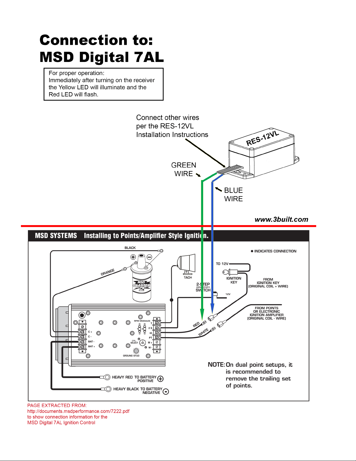
b. Normally Open Connection for Relay (8-amp max.) [diagram #1]
Typical for MSD Pro Mag 12
***Must perform “NORMALLY-OPEN MODE” steps in PROGRAMMING section. ***
This is typically used when an ignition system must be grounded to shut off the vehicle.
Blue Wire –The wire will be attached to the vehicle’s electrical system. The OEM RUN/STOP switch has two wires. One
comes from the CDI and the other goes to the vehicle’s ground. Splice the Blue Wire between the CDI and the OEM
Run/Stop switch. Attaching the Blue Wire to an incorrect wire may damage the CDI or other electrical component. Use
caution and consult a professional if unsure.
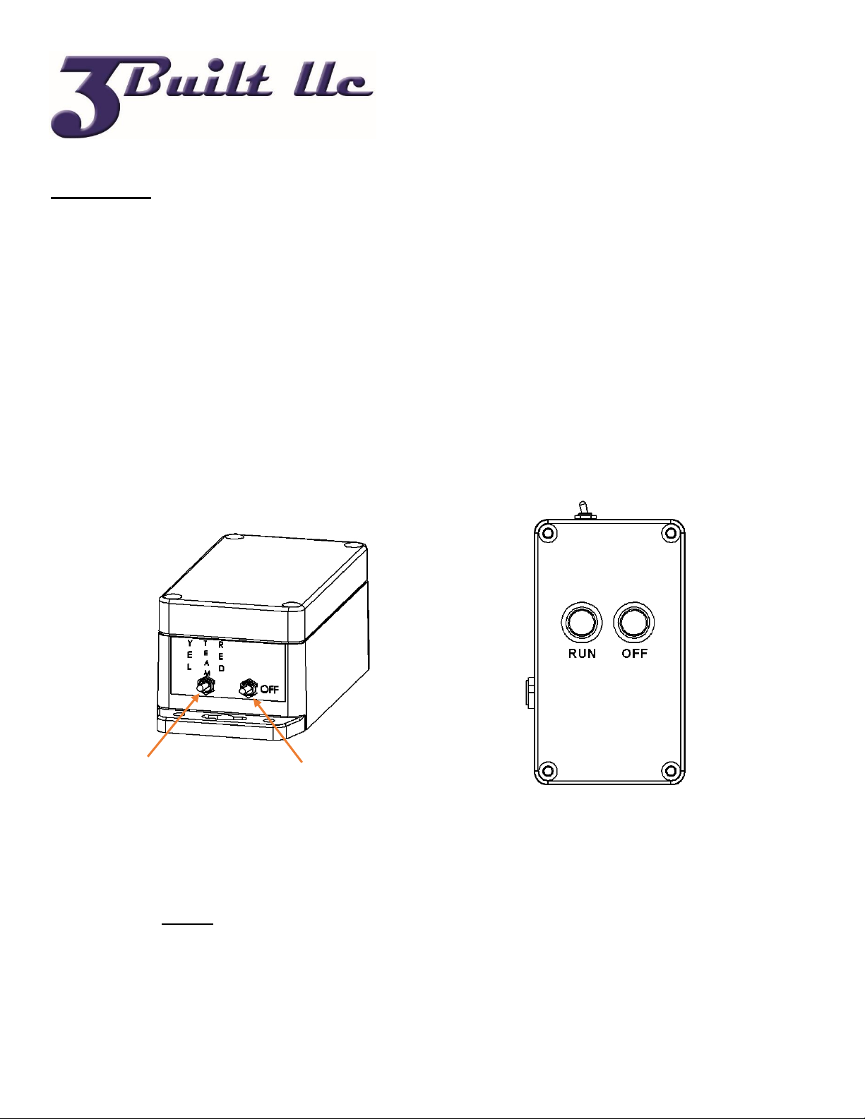
RECEIVER
1) Flip the POWER switch on the side of the Receiver.
a) The Yellow LED will illuminate and the Red or Green LED will blink three time rapidly.
i) Red blinks indicate Receiver is in Normally Closed operation (default)
ii) Green blinks indicate Receiver is in Normally Open operation
b) After the startup blinks, the system will settle on one of three colors
i) Blue –System is in Team mode. Only Team Transmitters will activate the Receiver.