AVERTISSEMENT: Le Switch ne doit pas rester sans bloc
d’alimentation ni plaque vierge dans l’emplacement (sauf pendant
le remplacement du bloc d’alimentation). Serrez toutes les vis avec
un tournevis approprié.
AVERTISSEMENT: Soyez prudent en démontant les blocs
d’alimentation, ils sont peut-être chauds. Le remplacement des
blocs d’alimentation doit être terminé en moins de deux minutes
pour éviter de perturber le refroidissement normal.
VORSICHT: Bevor Sie den PSU hinzufuegen, lesen Sie die
Sicherheitsanweisungen, die im Handbuch aufgefuehrt sind.
VORSICHT: Die PSU muss vor dem Ausbauen von der
Stromversorgung getrennt werden. Eine PSU darf erst an die
Stromversorgung angeschlossen werden, nachdem Sie installiert
wurde.
VORSICHT: Der Switch darf sich nicht ohne PSU oder Blende im
Steckplatz befinden (außer während des Austausches der PSU).
Ziehen Sie alle Schrauben mit einem geeigneten Schraubendreher
fest.
VORSICHT: Beim Ausbau der PSU muss beachtet werden, dass
diese sehr heiß sein kann. Der Austausch von PSUs darf nicht
länger als 2 Minuten dauern, so dass der normale Kühlbetrieb
nicht unterbrochen wird.
Replacing a Failed PSU
To remove a PSU from the rear panel of the Switch:
1Remove the power cord from the failed PSU.
2Loosen the screws on the PSU using a suitable screwdriver.
3Gently slide the PSU from the Switch.
4Orient the replacement PSU so that the screws on the front of the
PSU are towards you and the LED is on the left hand side, as
illustrated in the figure opposite.
5Slide the PSU into the slot.
6Tighten the screws on the PSU to secure it to the Switch.
7Insert a power cable in to the PSU and connect to the mains
power.
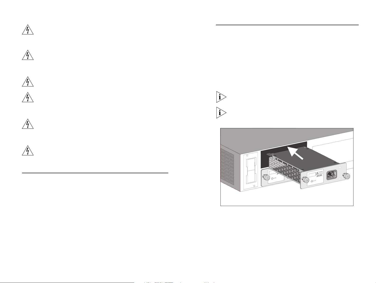
Adding a Second PSU
1Remove the blanking plate (if necessary), by undoing the screws,
using a suitable screwdriver.
2Orient the replacement PSU so that the screws on the front of
the PSU are towards you and the LED is on the left hand side, as
illustrated in the figure below.
3Insert the PSU into the slot.
4Tighten the screws on the PSU to secure it to the Switch. Insert
a power cable in to the PSU and connect to the mains power.
Remember to keep hold of the blanking plate for use when a
PSU is removed but not replaced.
The PSU can only be inserted one way as it will not slide fully
into the unit if inserted incorrectly.
2 3


