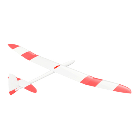
3d-printz Mini Sinbad 1200 User manual

Mini Sinbad 1200
Rev 0.0 – 08.01.2021
3d-printz Original
Take-off-weight: ca. 400g (LW-PLA) ca. 700g (PETG)
Span: ca. 1200 mm
Airfoil: Original Sinbad / RG15
CG: 45 mm
additional Material:
RC-Components
Bowden
CA medium and thin viscosity
Cutterknife
Sandpaper
4mm Carbonrod
(2x 465mm forFloaterwing, 2x 360mm for Acro Wing,
1x 45mm, 1x 65mm for Wingmount)
3mm Carbonrod 105mm
2mm Carbonrod 230mm bzw. 45mm
some Lead
4 round Magnets 10x4mm
Plasticscrew M6
Screwnut M6
RC Components:
RC Receiver
Battery (f.e. NimH 400mah - AAA for Gliderversion)
2x or 4x Microservos
Trivia:
The Mini Sinbad was developed as an easy-to-fly slope glider. The possibility of flying it
with the slow original airfoil only with rudder or with the faster RG 15 wing extends its field
of application and provides variety. The slow flight characteristics are excellent and with
the faster wing the small vintage glider can also pick up speed properly.
The flight behavior benefits from low weight so LW-PLA is the best choice of material, but it
can also be printed with Standard PLA or PETG.


Assembling
First check whether all parts according to
the list above are present and intact. If
necessary, sand off residues with
sandpaper and also roughen the adhesive
surfaces a little. The rudder hinges are still
a bit stiff due to production - move them
back and forth until they run smoothly, if
necessary sand them, but be careful! The
best way to assemble the fuselage is to
use the Bowden cable sleeves as guide
rails. Join Fus2, Fus3 and Fus4 in this way
and glue the parts over a large area with
medium-viscosity superglue! Make sure
that the individual parts are correctly
seated, the Bowden cable tubes will help you and act as guide rails. But be careful not to
glue the bowdens to the fuselage parts, they should remain freely movable! Use some
activator to get a strong adhesive bond!

Next, connect VertStab to Fus4 - you need a
carbon rod with a diameter of 3mm and a
length of
105mm. First
carefully check
the stick for fit,
then join Fus4
and VertStab
with superglue
- make sure that
the alignment
is correct - here you can orientate yourself
on the Bowden cable housings. As soon as
the glue has dried (use activator!) You can
glue HorStab top onto the rudder. Pay attention to the correct alignment, the part has a
small shoulder which has to be glued to the rudder, but not to the tail unit. It is best to fix
the part with some adhesive tape before gluing and check the ease of movement of the
rudder - it should movable absolutly free. For the attachment of the horizontal stabilizer 2
pcs. 2mm carbon rods are required (see page 1). First glue HorStabR2 with HorStabR1,
then insert the rods and then connect the right half of the tail unit with VertStab so that you
have the right side of the tail unit ready. Then push HorStabL1 onto the bars and check
whether the connecting pieces between the two tail unit halves lock into each other proper
- this is essential so that the elevator can move properly later. Now glue HorStabL1 with
VertStab and HorstabR1 (make sure that the connector between the oars is firmly and,
above all, connected straight with thick superglue!)
After the last part of HorStabL2 has been glued to the
rest of the horizontal stabilizer, you can continue with
the wings.

To assemble the wings, 2 carbon rods with a 4mm diameter are required (465mm for
Floaterwing and 360mm for Acrowing). The assembly is explained here using the example
of the floater wing, but works in exactly the same way for acrowing.
First insert the carbon rod into the Wingjoiner and carefully assemble one wing half without
glue. Check immediately whether the recess for the carbon rod is free, the manufacturing
process may cause small impurities to be present. This must be carefully pierced with the
rod. To do this, carefully twist and push the rod back and forth until the channel is free - but
be careful! The fit of the Wingjoiner in the Wingcenter should also be checked before
bonding and, if necessary, sanded down for a snug fit.
When everything fits, the carbon rod
can be inserted into the Wingjoiner and
the WingcenterL glued to the
Wingjoiner - it is best to use thick
superglue and apply it generously! Now
the wing can be glued part by part on
both sides, always making sure that the
surface segments are flush.
After the wings have been glued, they
can be screwed to the corresponding
Wingadaptermount
(„Flächenaufnahme) (attention - as with
the "Wingjoiner" part, there is also a
part for the floater and a part for the
acrowing).
To do this, insert an M6 hexagon nut into the recess provided in the Wingadaptermount
and fix the wing from above with an M6 plastic screw. After the adapter and wing are
connected, the fit between the fuselage and wing can be tested and, if necessary, sanded.
The 2 tabs of the Adaptermount should slide into the corresponding recesses in the
fuselage with light pressure and then be secured with 2 carbon rods (4mm diameter). The
locking pins should have a snug fit with enough friction not to loosen in flight. Alternatively,
other types of security can also be used.
Last but not least, the parts cockpit, canopy, motorspant and Fus1 or motor nose are
beeing assembled as seen in the explosion view. To glue the canopy and cockpit at the
right angle, the fuselage itself can be used as a template - apply glue, position the parts
with the help of the fuselage and use the activator. 4 round magnets 10x4mm are used to

fix the canopy, which are glued into the recesses provided. The nose can be designed
either as a motor or glider nose, with the motospant being used as an intermediate piece
in both versions. The part Fus1 should be glued at the very end of assembling, after
installing the RC Components when you set your CG, as it can be used as a chamber for
trim weights. „Motorspant“ can be drilled through with the needed holespacing for the
motor assembly. The motor shaft should be long enough to reach out through the motor
nose.
Deflections
Using a CG of 45mm we recommend following throws:
Aileron: +/- 8mm
Elevator: +/- 7mm
Rudder: Maximum
CG
The right center of gravity is essential for comfortable flight behavior. This is why you
always should test it out yourself. The starting value can be chosen around 45mm behind
the leading edge. If the flight behavior is unstable, move the center of gravity further
forward. If more agile flight behaviors are desired, the center of gravity can be shifted
further back.
Please note that the center of gravity and the throws should be discovered by the pilot
himself for each build!
We wish you a lot of fun flying your Mini Sinbad!
Table of contents
Other 3d-printz Toy manuals
Popular Toy manuals by other brands

Carson
Carson Angry Bug 2.0 Toxic Spider 2.0 2.4 GHz instruction manual

LEGO
LEGO STAR WARS 7879 Building instructions

dji
dji T20 user manual

Durafly
Durafly Bonanza instruction manual

Seagull Models
Seagull Models L-4 Grasshopper 90 inches Assembly manual

Mountain Models
Mountain Models Boomer EX 2 Builder manual

Horizon Hobby
Horizon Hobby Ultra Micro F4U Corsair RTF/BNF instruction manual

Horizon Hobby
Horizon Hobby E-FLITE UMX Timber X instruction manual

Odyssey
Odyssey Rampaging Rex instruction manual

Joysway
Joysway MAGIC VEE V5 instruction manual

Mega Bloks
Mega Bloks Musical Farm manual

Walkera
Walkera V18G01 instruction manual