IMPORTANT NOTE: 3DHS Recommends ONLY High-Torque, Digital, Metal-gear Servos for this
aircraft. Suitable part numbers include Hitec HS-7955TG, JR 8611A, and JR 8711A. DO NOT
attempt to use nylon-geared servos on this airplane.
THIS AIRCRAFT IS NOT A TOY! IT IS A HIGH PERFORMANCE AEROBATIC AIRCRAFT AND
IMPROPER SETUP AND/OR USE COULD RESULT INJURY OR DEATH.
Assembly Instructions
UNPACK
Unpack your airplane and examine the components. Check for damage of any kind. If you find any
damage, contact 3DHobbyShop and report the damage.
COVERING SEAMS
There are many seams in the covering on this aircraft where one color meets another. We recommend
using a covering iron or trim sealing tool to go over all of the covering seams on your Extra. This will help
to prevent any peeling of the covering. Repeat this periodically.
WRINKLES
Your Slick was packed at the factory without any wrinkles in the covering. You may notice some wrinkles
now; more likely, you will notice a few in a day or two or the first time you take the plane out to the flying
field. These wrinkles are the result of wood shrinkage and/or expansion. Balsa wood changes size and
shape slightly as it is exposed to varying humidity in the air. This is a natural property of balsa wood. As
your airplane adjusts to the weather in your part of the world, wrinkles may appear and disappear.
Wrinkles may be removed with the gentle application of heat to the covering material on your airplane,
using an iron and/or heat gun. Apply the heat gently: the covering material will shrink as you apply the
heat, and this will remove the wrinkles. BE CAREFUL! Too much heat applied too quickly can damage
the covering, either by causing it to pull away from the wood at seams and corners or even by melting it.
Wrinkles do not affect flight performance.
COVERING MATERIAL
Your Slick is covered with genuine OraCover material, and we have included repair sections in your kit. If
you need to repair larger sections, matching covering is sold at most hobby stores under the “UltraCote”
brand.
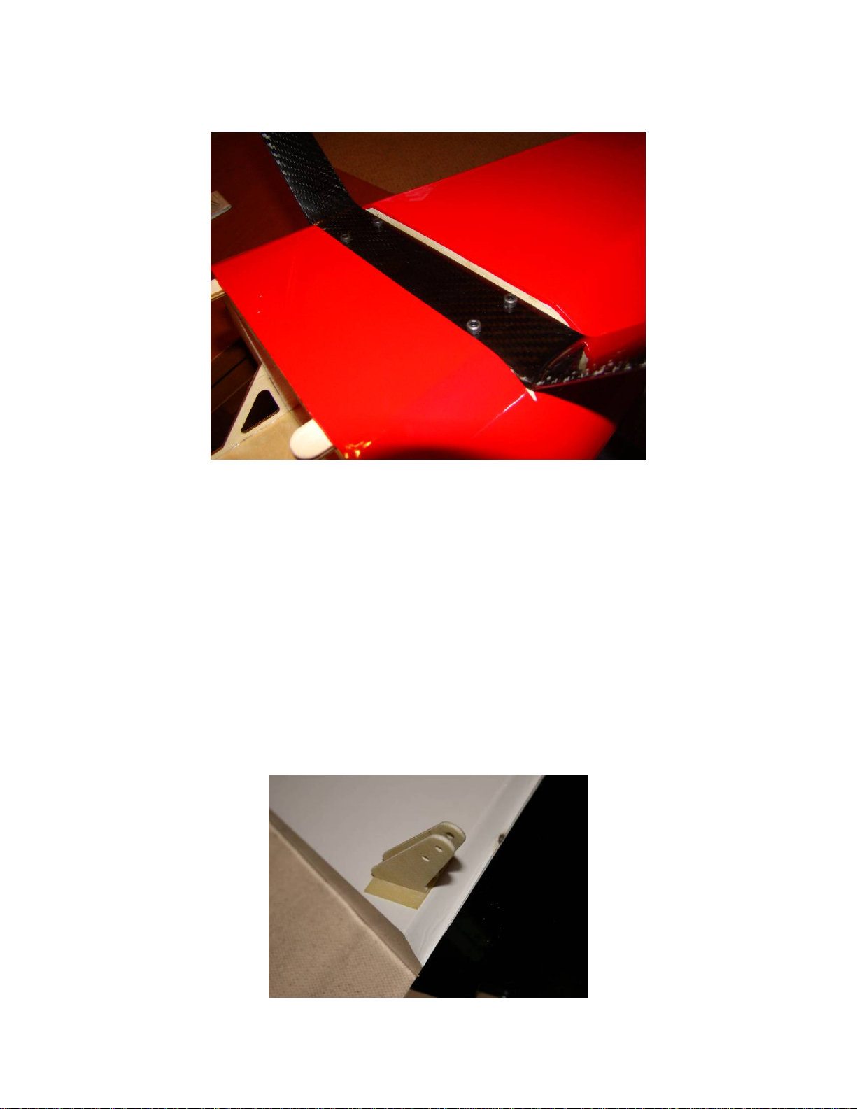
Hinging the Rudder
Your Slick uses hinge-point type hinges. The aileron and elevator hinging is done for you already. You
will need to hinge the rudder.
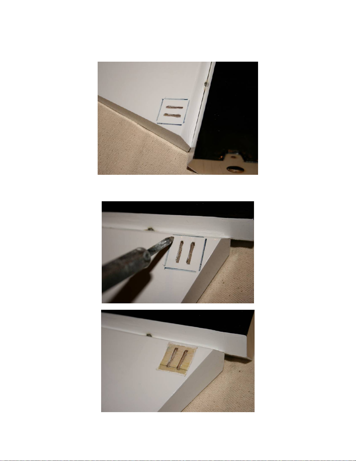
The hinging procedure is illustrated below using a typical surface, in this case a horizontal stab, but your
rudder uses the same procedure.
Apply the Vaseline only to the center of the hinge point where the two halves hinge together. We have
also used oil applied with a syringe, but the Vaseline stays in the center of the hinge point better than oil.