3DHobbyShop.com Yak 54 User manual

1
3DHobbyShop.com
Yak 54 55” Assembly Manual
Thank you for purchasing this 3DHobbyShop ARF RC aircraft. If you have any issues, questions,
concerns or problems during assembly, please contact our tech department at:
SAFETY in Assembly
During assembly of this aircraft, you will be asked to use sharp knives and hobby adhesives. Please
follow all safety procedures recommended by the manufacturers of the products you use, and always
follow these important guidelines:
ALWAYS protect your eyes when working with adhesives, knives, or tools, especially power tools. Safety
glasses are the best way to protect your eyes.
ALWAYS protect your body, especially your hands and fingers when using adhesives, knives, or tools,
especially power tools. Do not cut toward exposed skin with hobby knives. Do not place hobby knives on
tables or benches where they can roll off or be knocked off.
ALWAYS have a first-aid kit handy when working with adhesives, knives, or tools, especially power tools.
ALWAYS keep hobby equipment and supplies out of the reach of children.
SAFETY in Flying
ALWAYS fly your aircraft in a safe area, away from spectators.
ALWAYS fly your aircraft in a safe manner, within your control.
NEVER fly too close to yourself.
ALWAYS wear eye protection while operating your model aircraft.
ALWAYS keep your hands and body clear of propellers.
ALWAYS observe lipoly battery safety procedures.
REQUIRED ITEMS
Thin CA Glue
Medium CA Glue
Hobby Knife
Small Phillips Screwdriver
Set Metric Allen Wrenches
Scissors
Small Pliers
Clear Tape
Wire Cutters
Paper towels
1/16 inch drill bit
Epoxy glue (optional)

2
WRINKLES
Your Yak 54 was packed in plastic at the factory without any wrinkles in the covering. You may notice
some wrinkles now; more likely, you will notice a few in a day or two or the first time you take the plane
out to the flying field. These wrinkles are the result of wood shrinkage and/or expansion. Balsa wood
changes size and shape slightly as it is exposed to varying humidity in the air. This is a natural property
of balsa wood. As your airplane adjusts to the weather in your part of the world, wrinkles may appear and
disappear.
Wrinkles may be removed with the gentle application of heat to the covering material on your airplane.
The best tool to use is a heat gun. Apply the heat gently: the covering material will shrink as you apply
the heat, and this will remove the wrinkles. BE CAREFUL! Too much heat applied too quickly can
damage the covering, either by causing it to pull away from the wood at seams and corners or even by
melting it. The covering will shrink at low temperature with patient application of heat. Wrinkles do not
affect flight performance.
WING ASSEMBLY
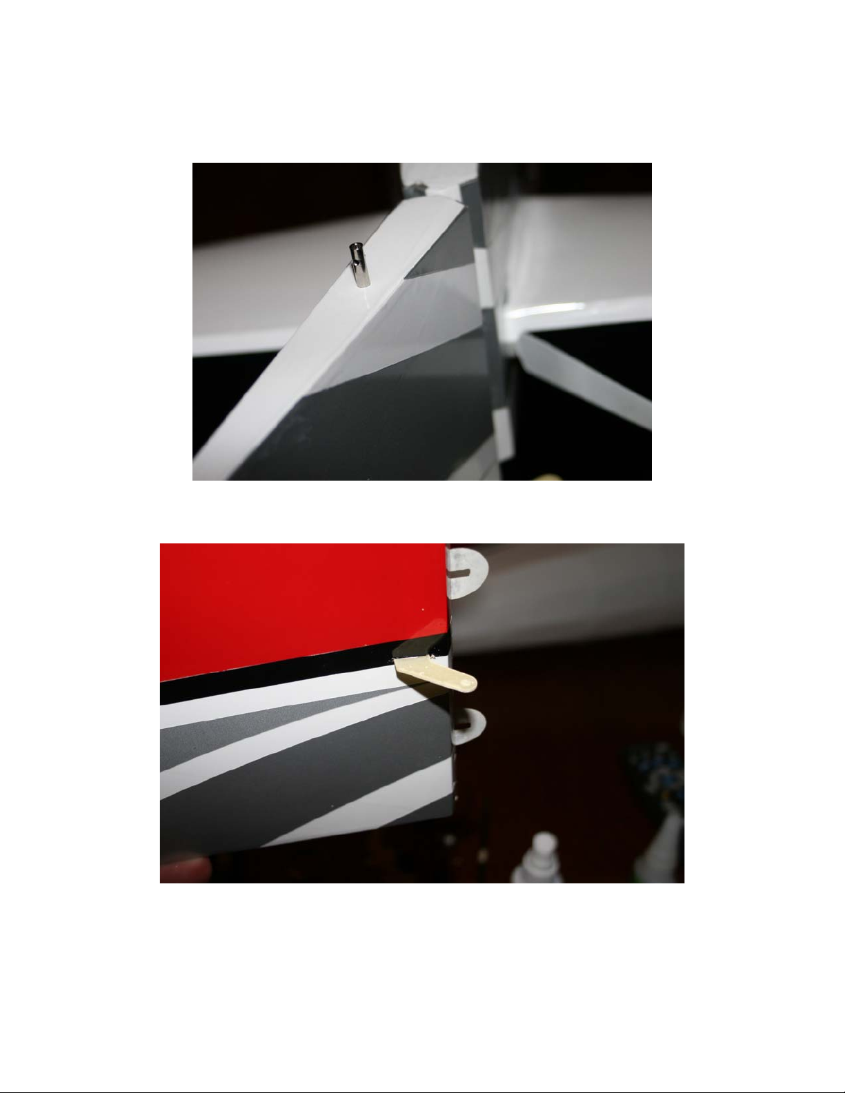
The ailerons hinge onto the wings using 4 hinges each. The hinges are already installed into the wings,
but need to be glued with THIN CA glue. Check the fit of the aileron to be sure the color stripes line up on
the wing, and flex the aileron to be sure that it moves freely and the hinges flex easily. Drip two large
drops of THIN CA glue into the aileron hinge joint right on top of each hinge. The THIN CA glue will wick
into the hinge slots and penetrate the wood, forming a strong hinge joint. Use two large drops per hinge,
no less. After the ailerons are hinged, install the supplied wing decal as shown.
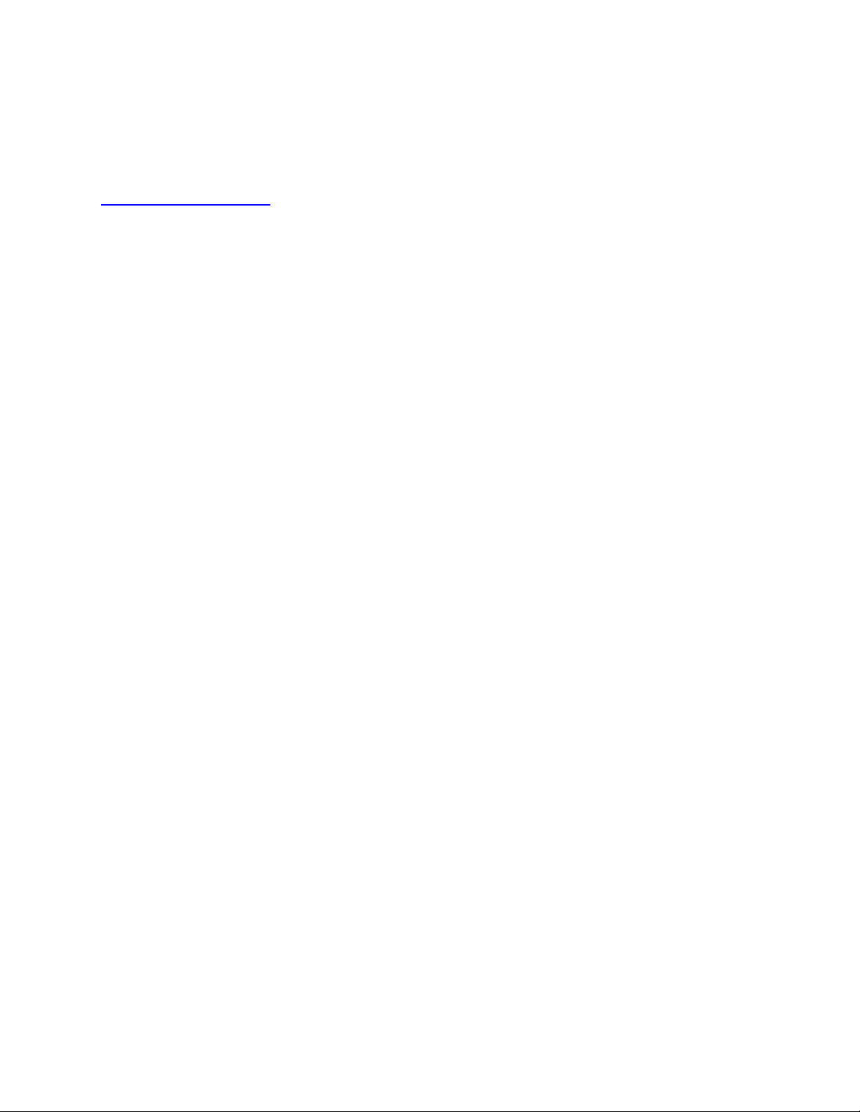
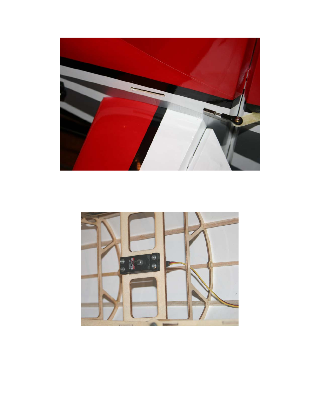
Locate the aileron servo mount on the bottom of the wing and remove the covering over the hole. The
best way to remove covering on this airplane is with a hot soldering iron tip, as this seals the edge of the
cut. However, you can also use your hobby knife to remove the covering. Also remove the covering over
the control horn slot in the position shown.

3
Test-fit the control horn into the slot to make sure it installs easily – you do not want to experience a
problem inserting the horn when you have CA glue on it. Install the control horn, first dripping medium
CA into the hole, then pushing the horn in, then adding thin CA around the horn. Allow to dry.
NOTE: Install all control horns on this airplane in this same way.
Attach the servo extension to the aileron servo lead.
Use the string installed inside the wing to pull your aileron servo lead through the interior of the wing as
shown.
Assemble the pushrod connectors onto the servo arms as shown. Use CA glue or threadlocker to lock
the nut on the bottom of the arm. If you do not use CA glue or threadlocker on all of the nuts on this
aircraft, they will come loose in-flight and the airplane will crash.
Insert your servo into the mount hole in the wing and attach with the servo mounting screws included with
your servos. The head of the servo (where the servo arm attaches) should be toward the FRONT of the
airplane.
Make and install the aileron pushrod as shown. Be sure to use CA glue or thread locker on the screw
and nut that attaches the ball-link to the control horn, and on the nut that attaches the pushrod connector
to the servo arm. If you do not use CA glue or thread locker on all of these ball-link screws on this
airplane, they will come loose in-flight and the airplane will crash. Trim the aileron pushrod to proper
length.

4
Repeat all of these steps for the other wing. Let the wings cure and move on to the fuselage and tail.
FUSELAGE/TAIL ASSEMBLY
Attach the landing gear to the fuselage with two 3mm black screws as shown BEFORE attaching the
wheels to the landing gear.

5
Install wheels onto axles and secure with wheel collars. Install axles and wheels into pants and bolt pant
assembly onto landing gear as shown, using the locknuts.
Remove the covering over the horizontal stabilizer opening and elevator servo openings as shown.

6
Locate the carbon wing-spar tube. Slide it into the fuselage tube.
NOTE: Due to the high-performance nature of this airplane, the carbon wing tube must be a snug-fit into
the wing and fuselage. It may be necessary to lubricate your wing tube from time to time. We
recommend the use of non-stick cooking spray as a lubricant.
Locate the horizontal stabilizer. Slide the stabilizer into the fuselage.
Align the stabilizer with the fuselage in all directions. Check the alignment with a ruler, and check to
make sure the stabilizer is level with the wing tube. It may be helpful to temporarily slide the elevators
into their slots (DO NOT GLUE THE ELEVATORS IN YET!) to help check alignment. This alignment will
take some time.
When you are satisfied with your stabilizer position, use thin CA glue to glue the stabilizer into the slot.
The fit between the stabilizer and the fuselage is meant to be a tight fit. If you need to sand or trim the
slot to achieve proper stabilizer alignment, do so, and if the fit is now loose, use Epoxy glue instead of CA
on this joint. Epoxy will fill any gaps better than CA.

7
Locate the rudder. Measure 2 inches back from the front hinge line on the bottom of the rudder, and drill
a 1/16” hole on the bottom. Using CA or epoxy glue, glue the tailwheel tiller keeper into the bottom of
the rudder as shown. NOTE: The tailwheel keeper is the same part as the rudder pull-pull cable ends.
Locate the slot in the rudder for the rudder control horn, remove the covering over the slot, and glue the
control horn into the rudder as shown with medium and thin CA, using the same procedure as for the
aileron horns. Test fit the horn before applying CA glue, as you did before.
Slide the rudder into the rear of the fuselage/vertical stabilizer and use two large drops of CA glue on
each rudder hinge. Slide the tailwheel tiller wire into the tiller wire keeper on the rudder, and use two
wood screws to attach the tail-wheel bracket to the bottom of the fuselage as shown.

8
Prepare the elevator halves. Install the control horns into the bottom of the elevator halves just as you
installed the horns into the ailerons.
Insert the elevators into the horizontal stabilizer. Check for alignment and free motion of the elevators.
Because good 3D flight requires extreme elevator throw, leave a small (1-2mm) gap between the
elevators and horizontal stabilizer to allow maximum throw. Apply two large drops of thin CA glue to each
hinge. Do not use less than two large drops.
Install your servo extensions onto the elevator servos.
Install the elevator servos as shown in each side of the fuselage.

9
Make and install the elevator pushrods in the same way you did the aileron pushrods.
Locate the slot in the fuselage for the rudder pull-pull cable exit, and remove the covering, as shown.

10
Install the rudder servo into the fuselage as shown.
The rudder pull-pull cables are assembled as shown in this diagram below. Begin by assembling the rear
(rudder mounted) end of the cables. Crimp the brass tube crimp sleeves securely with pliers (but not wire
cutters, you might accidentally cut the crimp sleeves in half) and add a drop of thin CA to each crimp
sleeve after crimping.

11
Install the rudder pull-pull cables onto the rudder horn, feed the cables into the fuselage through the slots,
and guide them to the front. The cables should cross over each other ONE time, making an X shape
inside the fuselage. Make sure the cables do not become twisted. Assemble the forward ends of the
pull-pull cables and attach them to the rudder servo horn, using the adjustors to set the tension. We want
the cables to be snug, with no sag and no play at the rudder-end of the system, but not severely tight.
Over the life of your Yak, you will need to periodically tighten these rudder cables. Slack rudder cables
can cause poor handling and lead to major trim problems on your Yak.
Use motor mount to mark holes in the firewall in the proper location as shown.
Drill holes in marked locations and install brushless outrunner motor onto firewall as shown.
NOTE: Your kit includes both 4mm nylock nuts and 4mm T-nuts for motor mounting. You may use either
style of nut, as you prefer.
NOTE: You may need to enlarge the center hole in the firewall to fit your motor’s shaft collar.

12
Install the ESC as shown.
If your ESC includes a switch, install into the fuselage side near the ESC.
NOTE: Do not simply allow your ESC switch to flop around inside the fuselage. Either mount it to the
fuselage side or restrain it properly inside the fuselage so that the switch cannot be flipped to the “off”
position while in-flight.
NOTE: ESC cooling is extremely important. Do not use foam rubber, foam tape, or any other insulating
material in the mounting of your ESC. If you fly in extremely hot conditions, consider the use of an add-
on heat sink.

13
Your Yak kit includes a scale cowl baffle, it is attached to the cowl (if desired) with glue (we use thick CA,
epoxy also works well). Align the baffle with the cowl, and use tape as shown to hold it in-place for gluing
from the back side.
The baffle cuts almost all cooling airflow off. This would be acceptable on only a very cold day. For flying
in moderate to warm conditions, we suggest cutting away approximate 25% of the baffle to allow cooling
air to enter the airplane. For hot conditions, over 90 degF, please remove the baffle entirely.
The cowl is mounted onto the fuselage with 4 wood screws. These screws go into the small plywood
squares on the front inside of the fuselage. Soak these squares in thin CA glue to harden them before
proceeding.
The following procedure is helpful to be sure the wood screws hit the plywood squares.
First, make small holes into the plywood squares through the covering, with the cowl and canopy off.
Tape small pieces of paper over these holes, as shown, and mark the hole locations on these pieces of
paper.
Install the canopy hatch (if the canopy hatch is not installed when you fit the cowl, it may be
impossible to fit the canopy hatch after the cowl is installed!).
When you are satisfied with the cowl fit, tape the cowl to the fuselage with masking tape. Use the small
pieces of paper as guides to make holes in the cowl and install the wood screws.

14
Remove the canopy hatch. Use THIN CA glue to attach one side of the Velcro to the battery tray as
shown. Stick the opposite side of the velcro to your battery pack. Use at least 2 velcro straps to retain
the battery in the airplane, as shown.
Mount your receiver to the fuselage sidewall or a fuselage former in a convenient place using velcro, hot
glue, or foam tape. Connect all of the radio connections with appropriate servo extensions. Because
there are two elevator servos, one will need to run in the reverse direction from the other.
We recommend temporarily removing all of the servo horns on your aircraft before turning the radio setup
in the airplane on for the first time. Once your radio is powered, center all servo trims and sub-trims, then
re-install all servo horns.
WITHOUT the prop installed, reverse servos as necessary. NEVER do servo reversing on an
airplane with the propeller installed, you may accidentally reverse the throttle channel, causing
injury.
WITHOUT the prop, run your motor, check for correct direction of rotation. Reversing motor rotation is
accomplished either within your ESC programming, or by reversing the connection of any two of the
motor-to-ESC wires.
Make sure the routing of radio wires inside the airplane is secure. Use nylon zip-ties and CA glue as
necessary to make sure your radio wires will not become tangled in the rudder servo arm or rudder pull-
pull cables.
Remove the covering from two bays on the bottom of the airplane as shown, to allow cooling-air to exit.

15
Scott’s Tip:
Sealing Hinge Gaps
Sealing hinge gaps is a discussion item that will draw as many unique responses as
there are people. Some claim wild performance increases, while others consider the task
unnecessary. With my full-scale experience to lean on, I think sealing the gaps is time well
spent. On the Sukhoi, we saw measurable performance increases in the form of increased
control surface effectiveness and a more solid feel by sealing the areas around the hinge
points with, believe it or not, foam. Similar results can be achieved by sealing the hinges on
yourYak – a process that takes no more than 30 minutes to complete.
From my perspective, the control most in need of a sealed hinge gap is the elevator.
In any case, I recommend sealing all three control surfaces gaps. There are two basic
materials that are commonly used to seal hinge gaps on model airplanes – tape and clear
covering. I prefer Blenderm clear tape as it sticks extremely well and doesn’t make a
crinkling sound when moved in the hinge. If you choose to use clear covering, make sure it
is a low temperature covering to match the stock film.
I generally apply the tape to the surface in short 6-8 inch sections to make the
application more precise and easier to control. For purely aesthetic reasons, I apply it to the
bottom of each hinge surface to hide the tape when viewed from above. While mostly clear,
Blenderm isn’t fully transparent. Go slowly and you’ll be rewarded with a clean
professional looking installation. Finally, be sure to fully flex the surface away from the
tape during application to ensure a full range of motion.

16
Scott’s Tip:
Sealing Hinge Gaps Continued

17
With the battery installed, but not connected, install your prop and spinner. Consult the motor
manufacturer for assistance in selecting a prop.
For the Torque revolution 4014T-570 power system, we recommend a 15x7 or 16x7 prop on 5S, or a
16x8 or 17x8 prop on 4S.
Check the balance of your Extra and move the battery pack as needed to achieve the desired Center of
Gravity measurement.
CENTER OF GRAVITY RANGE 95-110mm back from the leading edge of the wing where it meets
the fuselage. We recommend you start at the forward end of this range for easy landing
characteristics, and move back when you are ready to attempt aerobatics with your Yak.
If you cannot achieve the correct Center of Gravity by moving your battery, please add weight to the nose
or tail as necessary. Correct CG is much more important than total weight.
Test your power system in a safe manner on the ground before ever attempting to fly your aircraft.
Range check your radio system according to manufacturer’s instructions.
Make your first flight with the controls set on low rates. During the trimming phase, we recommend
landing with some throttle, not attempting to “dead stick” the airplane. This may mean you need to time
your flights and keep them a bit shorter than usual. After your first flights, check all control connections
and motor and prop mounts for tightness.
If you have any damage to your Yak, spare parts are available from 3DHobbyShop.com
Scott’s Tip:
Control Throws and Exponential
Throws (in inches) and Corresponding Exponential
Control Throws
Elevator
Low rate - 1" deflection - 30% expo
High rate - 3" deflection - 80% expo (use maximum throw allowed by bevels)
Rudder
max throw - just short of touching elevator - 80%expo
Ailerons
Low rate - 1.5" deflection - 30%expo
High rate - 2.25" defection - 60% expo
Remember, JR and Spektrum radios use positive (+) exponential, Futaba and Hitec
use negative (-).
The above throw measurements were taken at the aft edge of the ailerons
and elevator. Keep in mind that even the low throws mentioned here are relatively
aggressive, so be sure to also program the matching exponential listed to help
soften the model’s feel around center stick.

18
Table of contents
Other 3DHobbyShop.com Toy manuals
Popular Toy manuals by other brands

Hasbro
Hasbro Littlest Pet Shop Light Up Diorama... instruction manual

Carl Goldberg Products
Carl Goldberg Products Mirage 550 instructions

Faller
Faller 120322 quick guide

GRAUPNER
GRAUPNER Seenotrettungsboot manual

BLOTZ
BLOTZ B28-ME-008 instructions

Canon
Canon Creative Park Kissing Dolls Assembly instructions

AIRFIX
AIRFIX De Havilland Mosquito PR.XVI Assembly instructions

Faller
Faller DETACHED HOUSE manual

Phoenix Model
Phoenix Model Ka-8b ELECTRIC 6000 instruction manual

RC4WD
RC4WD VV-JD00015 quick start guide

Mega Construx
Mega Construx Kubros Halo Spartan Recon DXB91 Assembly instructions

Mattel
Mattel Matchbox DWR17 instructions