3DLab GANG PRINT BEAT PZL p.11c User manual

ASSEMBLY INSTRUCTION FOR
RC MODEL PRINTED ON 3D PRINTER
Visit our website and purchase a product which you are www.print-beat.com
interested in. Then you get an access for the file download in g-code or STL format.
Download the files onto SD card. We try to optimize the universal G-code output
for the widest selection of printers and we test our products on several printer
brands and configurations. In case you are owner of the Prusa 3D printer use for
the print the files prusa G-code
Print all of the model parts on the 3D Printer
- the supported type of filament is PLA
- minimum supported size of the printed surface is 20x20x15 cm
- for bonding of the model parts we recommend to use Super Glue (medium thick)
and Activator
Assemble the model according to the attached PDF manual
PRODUCT CONTAINS
STL files of RC model PZL p 11.C in 1/10 scale
Universal G-code of RC model PZL p 11.C in 1/10 scale optimized for 3D printers
SimpliFy3D factory files of RC model PZL p 11.C in 1/10 scale
Asssembly instructions in PDF format
Scale markings in PDF format
Weight of all printed parts
900 g
Takeoff weight
1250 g / (3s 2200mAh Li-Po, 4x servo, SC)
Length
78,5 cm / 30,9 inch
Wingspan
110 cm / 43,3 inch
MODEL SPECIFICATION
1
member of Group

WHATEVER YOU NEED
PLA filament for print model parts
FLEX filament for print tire
Super glue and Activator
Spring diameter 7 mm
10x screws diameter 3mm
1x screws diameter 12mm
Bowden wire
6x hinge
Electric motor (recommended 3536 1300kv)
Regulator
Li-Po Battery 3s 2250mAh
RC receaver
Propeller 12x6 / 13x5
PRINTED PARTS LIST - No./ Weight
2
40/5g
58/10g
44/4g
45/5g
41/9g
56/10g
43/2g
38/4g
42/4g
37/9g
24/4g
23/4g
26/4g
25/4g
16/22g
17/13g
13/26g
15/29g
14/25g
22/13g
19/25g
21/22g
20/29g
18/26g
04/32g
01/10g
02/18g
03/19g
06/33g
39/5g
57/1g
05/68g
08/65g
10/28g
11/5g
12/2g
11/20g
78/5g
77/1g
50/10g
49/7g
34/5g
35/5g
28/3g
27/3g
75/1g
74/1g
29/3g
30/3g
33/5g
32/5g
66-67/3g
53-55/1g
64-65/4g
68/1g
72/1g
73/1g
69/1g
70/1g
71/1g
76/1g
48/1g
47/1g
46/1g
59/2g
07/41g
61-62/6g
60/4g
79/11g
75/1g
79/11g
member of Group

3
PRINTED PARTS LIST
No. Parts name Colour Weight Infil Suport E. Multiplier Perimeter Main Location
1 Fuselage Green 10g 0% no 0,82 1 Fuselage_01_-_07
2 Fuselage Green 18g 0% no 0,82 1 Fuselage_01_-_07
3 Fuselage Green 19g 0% no 0,82 1 Fuselage_01_-_07
4 Fuselage Green 32g 0% no 0,82 1 Fuselage_01_-_07
5 Fuselage Green 68g 9% no 0,9 1 Fuselage_01_-_07
6 Fuselage Green 33g 0% no 0,82 1 Fuselage_01_-_07
7 Fuselage Green 41g 17% no 0,96 1 Fuselage_01_-_07
8 Body Green 65g 10% yes 0,91 1 Engine_08_-_12
9 Battery cover Green 5g 50% no 0,97 1 Engine_08_-_12
10 Ring Copper 28g 12% no 0,93 2 Engine_08_-_12
11 Engine Holder 20g 20% no 0,99 3 Engine_08_-_12
12 Cylinder Silver 2g 6% no 0,97 2 Engine_08_-_12
13 Left Wing Green 26g 0% no 0,82 1 Wing_13_-_36
14 Left Wing Green 25g 0% no 0,82 1 Wing_13_-_36
15 Left Wing Green 29g 0% no 0,82 1 Wing_13_-_36
16 Left Wing Green 22g 0% no 0,82 1 Wing_13_-_36
17 Left Wing Green 13g 0% no 0,82 1 Wing_13_-_36
18 Right Wing Green 26g 0% no 0,82 1 Wing_13_-_36
19 Right Wing Green 25g 0% no 0,82 1 Wing_13_-_36
20 Right Wing Green 29g 0% no 0,82 1 Wing_13_-_36
21 Right Wing Green 22g 0% no 0,82 1 Wing_13_-_36
22 Right Wing Green 13g 0% no 0,82 1 Wing_13_-_36
23 Left Ailerons Green 4g 0% no 0,82 1 Wing_13_-_36
24 Left Ailerons Green 4g 0% no 0,82 1 Wing_13_-_36
25 Right Ailerons Green 4g 0% no 0,82 1 Wing_13_-_36
26 Right Ailerons Green 4g 0% no 0,82 1 Wing_13_-_36
27 Strut Holder Green 3g 15% no 0,95 1 Wing_13_-_36
28 Strut Holder Green 3g 15% no 0,95 1 Wing_13_-_36
29 Strut Holder Green 3g 15% no 0,95 1 Wing_13_-_36
30 Strut Holder Green 3g 15% no 0,95 1 Wing_13_-_36
31 RepairKit-Damper Green 1g 10% 0,95 2 Wing_13_-_36
32 Wing Strut Green 5g 10% no 0,97 1 Wing_13_-_36
33 Wing Strut Green 5g 10% no 0,97 1 Wing_13_-_36
34 Wing Strut Green 5g 10% no 0,97 1 Wing_13_-_36
35 Wing Strut Green 5g 10% no 0,97 1 Wing_13_-_36
36 Wing Hex Green 1g 0% no 0,92 1 Wing_13_-_36
member of Group

PRINTED PARTS LIST
4
No. Parts name Colour Weight Infil Suport E. Multiplier Perimeter Main Location
37 Elevator Green 9g 0% no 0,82 1 Elevator_37_-_48
38 Elevator Green 4g 0% no 0,82 1 Elevator_37_-_48
39 Elevator Green 5g 0% no 0,82 1 Elevator_37_-_48
40 Elevator Green 5g 0% no 0,82 1 Elevator_37_-_48
41 Elevator Green 9g 0% no 0,82 1 Elevator_37_-_48
42 Elevator Green 4g 0% no 0,82 1 Elevator_37_-_48
43 Elevator Green 2g 9% no 0,9 1 Elevator_37_-_48
44 Elevator Green 4g 0% no 0,82 1 Elevator_37_-_48
45 Elevator Green 5g 0% no 0,82 1 Elevator_37_-_48
46 Axe Green 2g 9% no 0,9 3 Elevator_37_-_48
47 Hex Green 1g 0% no 0,82 2 Elevator_37_-_48
48 Strut Green 1g 9% no 0,9 2 Elevator_37_-_48
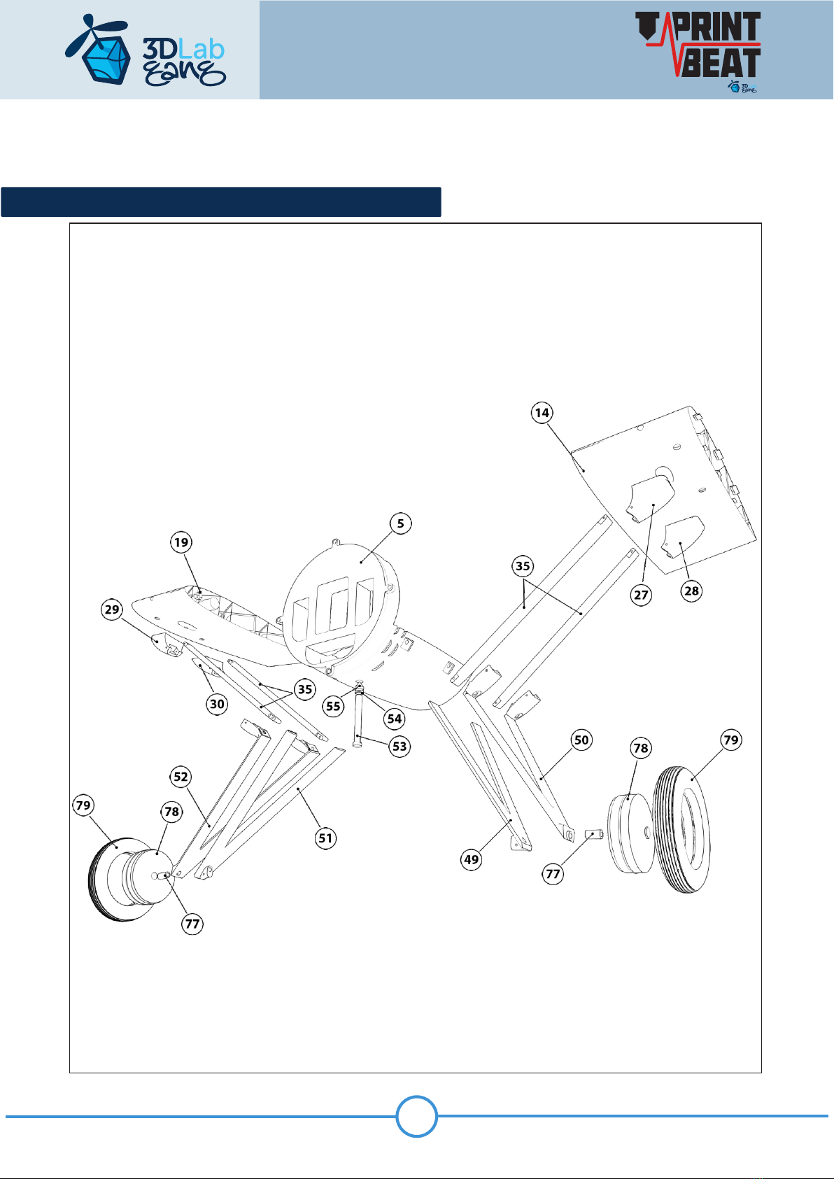
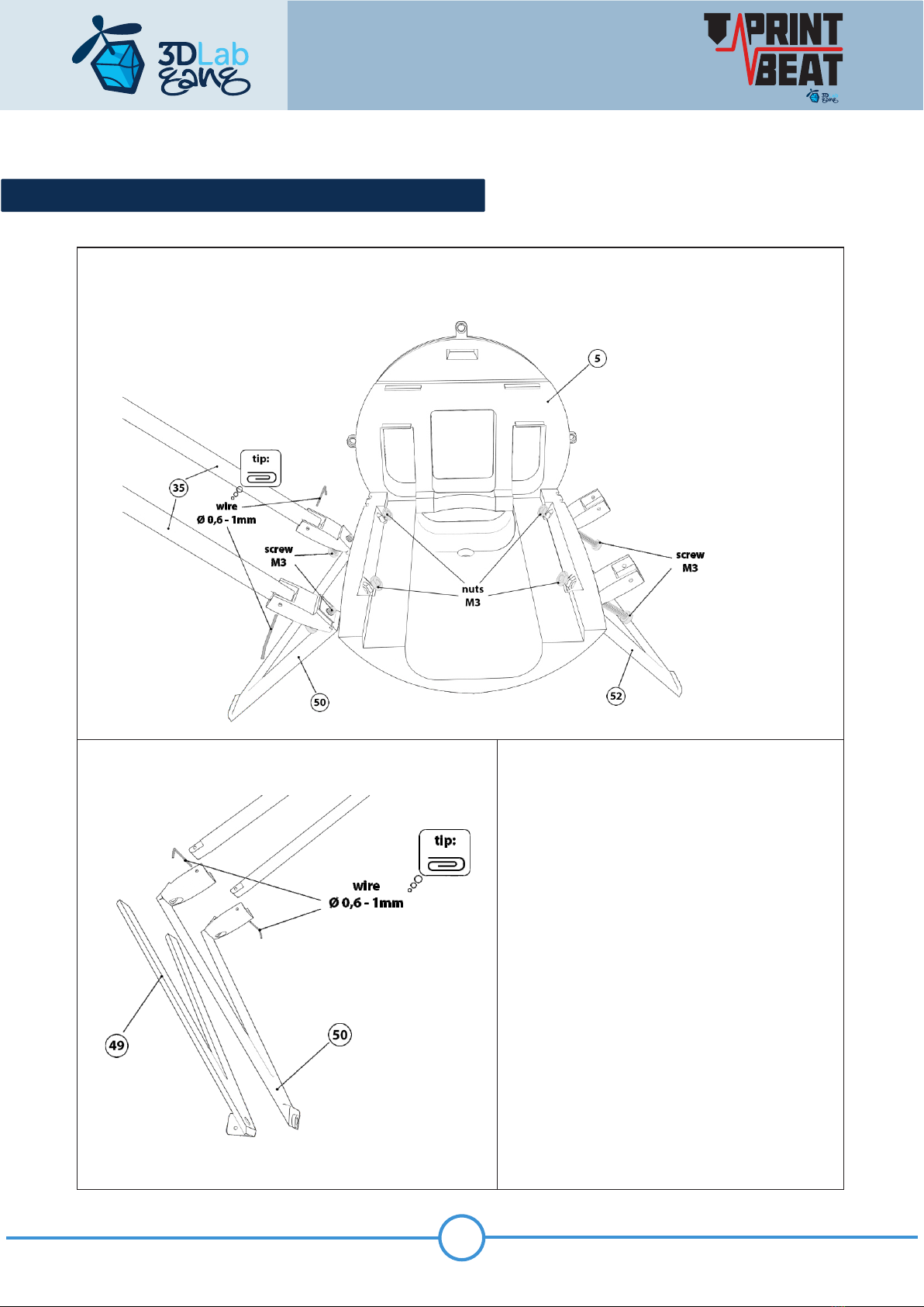
49 Landing gear Green 7g 20% no 0,9 3 Landing_gear_49_-_55
50 Landing gear Green 10g 20% no 0,9 3 Landing_gear_49_-_55
51 Landing gear Green 7g 20% no 0,9 3 Landing_gear_49_-_55
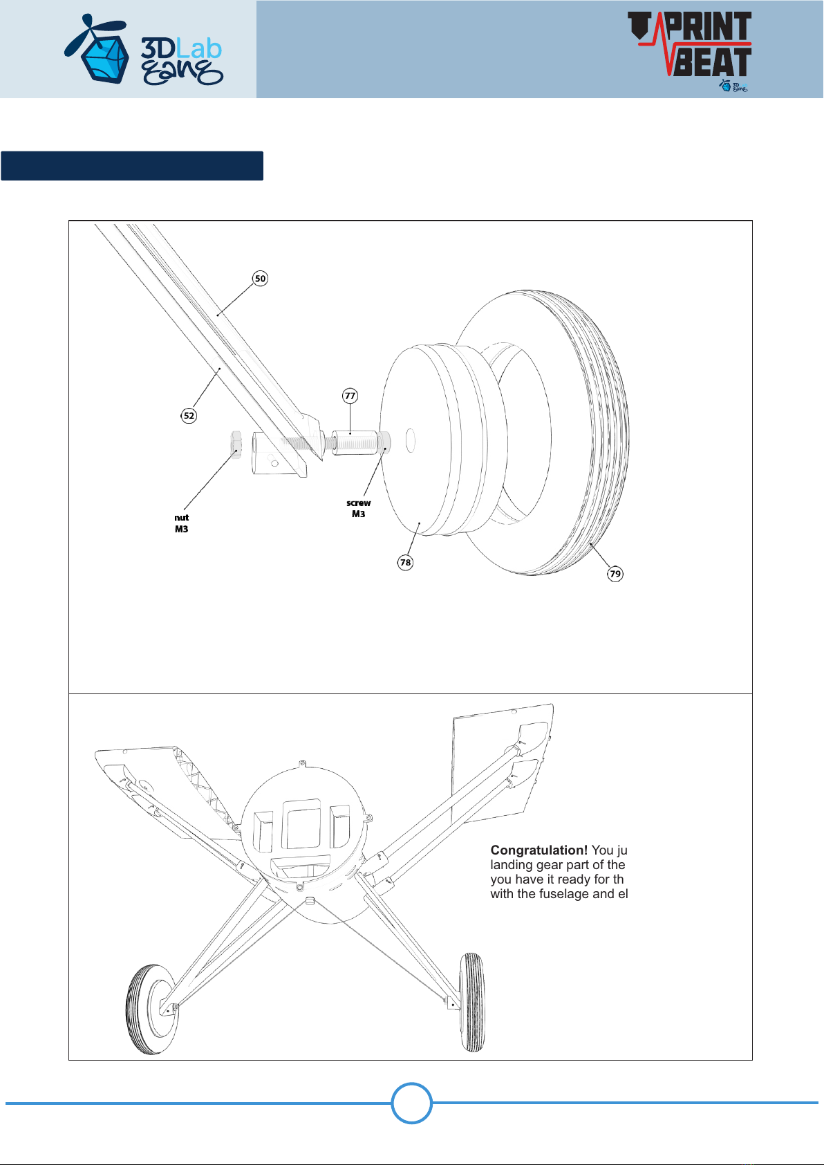
52 Landing gear Green 10g 20% no 0,9 3 Landing_gear_49_-_55
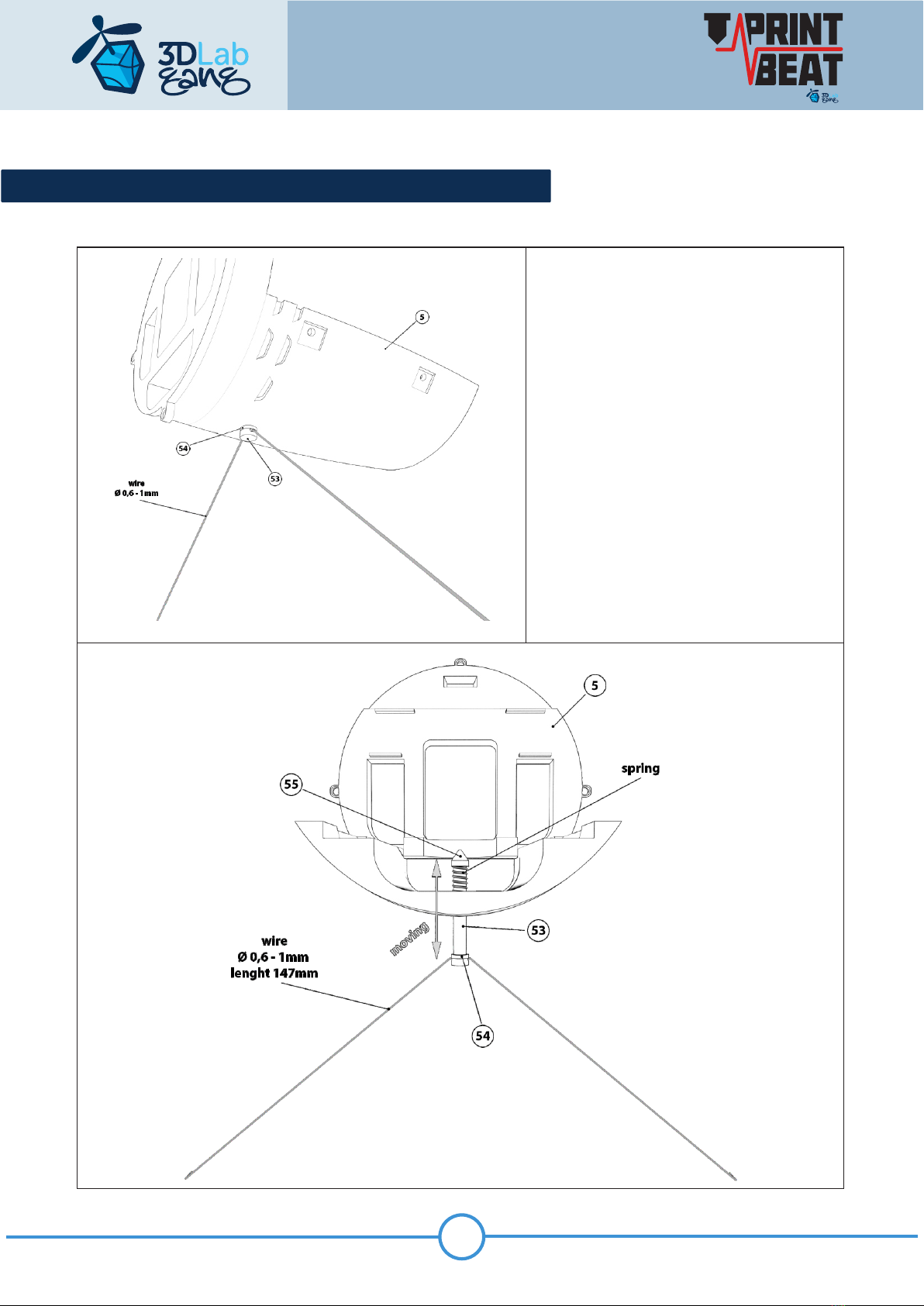
53 Damper Green 1g 20% no 0,9 5 Landing_gear_49_-_55
54 Damper Green 1g 20% no 0,9 5 Landing_gear_49_-_55
55 Damper Green 1g 20% no 0,9 5 Landing_gear_49_-_55
56 Rudder Green 10g 0% no 0,82 1 Rudder_56_-_59
57 Rudder Green 1g 0% no 0,82 1 Rudder_56_-_59
58 Rudder Green 10g 0% no 0,82 1 Rudder_56_-_59
59 Rudder Green 2g 0% no 0,82 1 Rudder_56_-_59
60 Propeller Green 4g 20% no 0,92 3 Propeller_60_-_63
61 Propeller Green 6g 20% no 0,92 3 Propeller_60_-_63
62 Propeller Green 6g 20% no 0,92 3 Propeller_60_-_63
63 Propeller Green 6g 20% no 0,92 3 Propeller_60_-_63
64 Spur Black 4g 15% no 0,98 3 Accessories_64_-_76
65 Spur Black 4g 15% no 0,98 3 Accessories_64_-_76
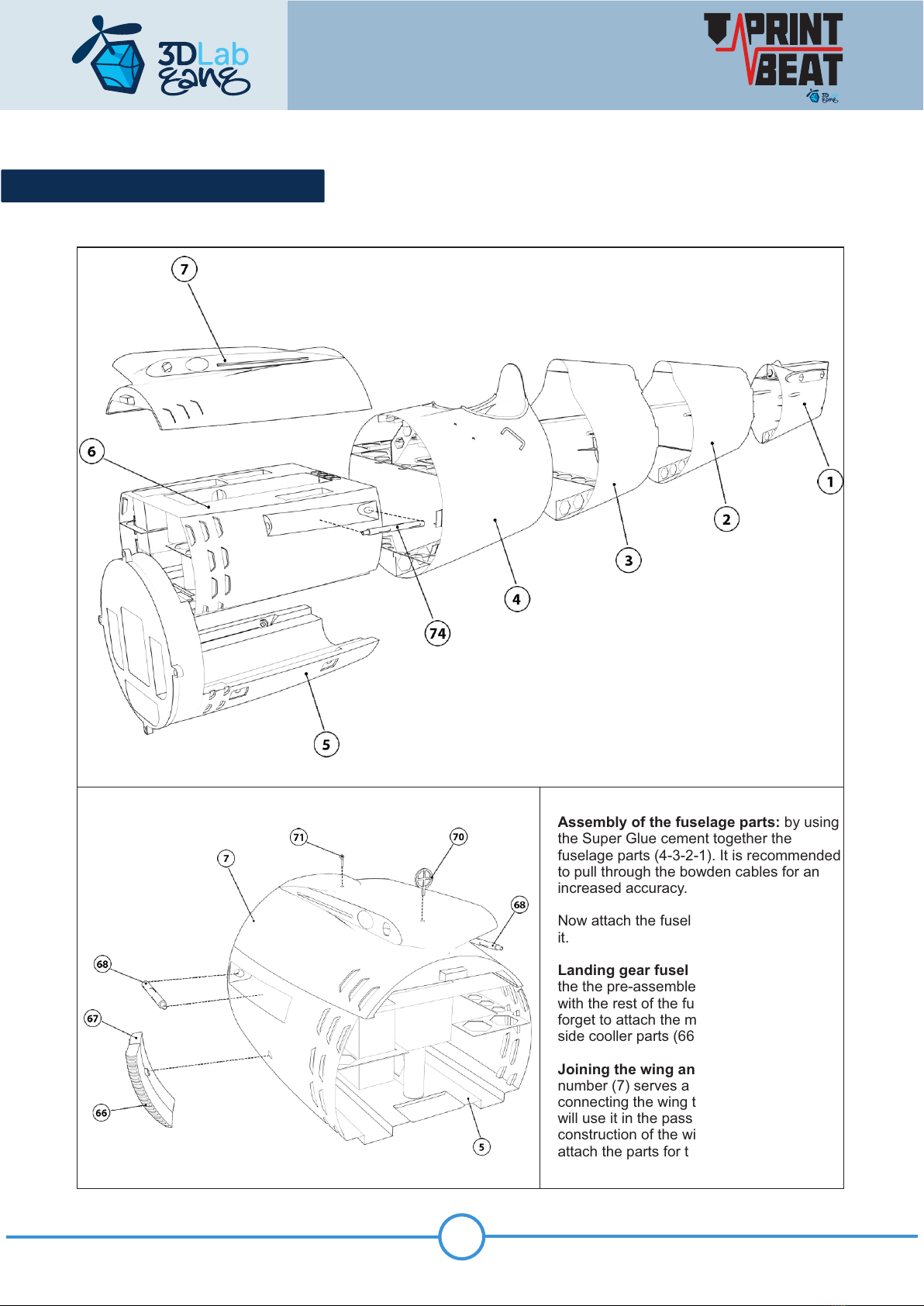
66 Cooler Black 3g 15% no 0,92 3 Accessories_64_-_76
67 Cooler Black 3g 15% no 0,92 3 Accessories_64_-_76
68 Dashboard Black 1g 0% no 0,98 1 Accessories_64_-_76
69 Glass Transp. 1g 0% no 0,92 1 Accessories_64_-_76
70 Gunsight Black 1g 0% no 0,98 1 Accessories_64_-_76
71 Gunsight Black 1g 0% no 0,98 1 Accessories_64_-_76
72 Hasp Black 1g 0% no 0,98 3 Accessories_64_-_76
73 Headrest Brown 1g 10% no 0,92 1 Accessories_64_-_76
74 Mach.Gun Black 1g 0% no 0,95 1 Accessories_64_-_76
75 Mach.Gun Black 1g 0% no 0,95 1 Accessories_64_-_76
76 Grip Green 1g 20% no 0,92 3 Accessories_64_-_76
77 Insert Green 1g 5% no 0,92 2 Wheel_77_-_79
78 Disc Green 5g 5% no 0,92 2 Wheel_77_-_79
79 Tire Flex 11g 0% no 1 2 Wheel_77_-_79
member of Group

LANDING GEAR AND SUSPENSION
The construction will start with the front lower part of the fuselage (5) to which the landing gear is
attached.
5
member of Group

LANDING GEAR AND SUSPENSION
Glue the parts of the landing gear struts
together (49-50) and then using M3 screw
and M3 nut fix it to the the bottom part of the
fuselage (5) Note: It is advisable to carefully
fasten the nuts with glue so that the
adhesive does not get into the thread, letting
you to dismantle the assembly in the future.
6
member of Group

LANDING GEAR STRUTS - SUSPENSION
Landing Gear Suspension System:
Insert the bowden cable (bent on the
template) into the part (53) and secure it
with a washer (54) and carefully glue it,
then insert it into the opening at the
bottom of the part (5). Then put on a
spring of diameter 10mm and lenght
45mm from the inside. Now secure the
assembly by gluing the part (55). Test if
the suspension system is functional and
then connect the bowden cable with the
landing gear strut (49-50) – this
assembled unit will be glued to the
fuselage part (6) later.
7
member of Group

LANDING WHEELS
Landing Wheels and their parts : Insert a 25 mm long screw M3 into the housing (77) with the
screw head towards the wheel disc (78) and put (part 77+screw) into the disk (78) and glue it. Then
mount the tyre (79) onto the wheel disc (78) and attach the complete wheel to the chassis and secure
the wheel with a nut M3 which you fix by Super Glue. Note: the wheel must remain free to rotate.
Congratulation! You just finished
landing gear part of the fuselage and
you have it ready for the connection
with the fuselage and electric motor
8
member of Group

Landing gear fuselage part: Now attach
the the pre-assembled landing gear unit (5)
with the rest of the fuselage and do not
forget to attach the machine gun (74) and
side cooller parts (66-67).
Now attach the fuselage part (6) and glue
it.
Joining the wing and the fuselage: part
number (7) serves as the centerpiece for
connecting the wing to the fuselage and we
will use it in the passage dedicated to the
construction of the wing. Now we can
attach the parts for the gunsight (70-71)
Assembly of the fuselage parts: by using
the Super Glue cement together the
fuselage parts (4-3-2-1). It is recommended
to pull through the bowden cables for an
increased accuracy.
FUSELAGE ASSEMBLY
9
member of Group

COCKPIT
Cockpit: Complete the part of the fuselage
number (4) where there is the cockpit with the
details - the instrument panel (68), the
headrest (73) and attach the handle (76).
Then glue the windscreen (69) and check if
the latch (72) fits into the opening and
correctly to secure part (7)
10
member of Group

Fin: Glue parts (56-57) and then attach them to the fuselage part (1), join the rudder parts (58-59) and insert
the hinges that join these two parts which must remain movable. Attach the tail skid parts (64-65) to the rear
fuselage part (1)
Note: It is necessary to draw out the servo bowden wire and attach it to the rudder before you glue the parts of
the rudder (59-58)
FIN
11
member of Group

TAILPLANE
Note: It is necessary to draw out the servo bowden wire and attach it to the elevator just before you join it with
the horizontal tailplane.
Elevators: join port (left) elevator parts (39-40) then starboard (right) parts (43-44-45), connect both parts
together with the axle(46), make sure that the pieces are in plane, install the hinges in place and stick them into
the taiplane that you already have attached to the rear fuselage part (1)
Horizontal tailplane: into the fuselage part (1) cement the hexagonal pins (47), then glue tailplane parts (37-
38) and (41-42), which you attach to hexagonal pins and glue the whole together with the struts (48-49) to the
fuselage (1)
12
member of Group

ENGINE PART - ELECTRIC MOTOR ATTACHMENT
Engine part: Fit the electric motor holder (11) into the fuselage part (5) so that the Print Beat logo is properly
legible, then adjust correct setting of the motor holder by insertion or removing according to the size of your
electric motor (then fix it by Super Glue).
Note: You can make a choice of two used sizes of the mounting disc.
Engine model: Install 9x engine cylinder (12) to part (8), then insert the engine cooling ring (10) – now it is the
right moment to install the electronic parts (regulator and electric motor). Then fix the assembly by the screw to
the fuselage part (5) and it remains to cover battery opening by the cover (9).
Congratulation if you finished this part of the model assembly and you have the fuselage complete. Now you
must still assemble the wing parts.
Propeller spinner: Put the propeller onto the mounting disc and insert the spinner (60), then put a nut into the
part (62) – the propeller unit is complete.
13
member of Group

LEFT WING ASSEMBLY - SERVO
Note: Before connecting the part (15) install the servo and run the servo cable through the prepared hole.
Left Wing Assembly: start by connecting the middle part (7) with the first wing part (13), then prepare the parts
14-15.
14
member of Group

Aileron: Glue together the parts with the installed servo (14-15-16) into which you put the inner part of the
aileron (23) fitted with a 0.9mm-1.2mm axle made from a bowden wire or paper clips, then install the outer part
of the aileron (24) with the axle from each side and connect both parts of the ailerons so that the axle fits into
the wing openings.
Warning: Apply the glue carefully so that the aileron remains movable.
WING ASSEMBLY - AILERON
15
member of Group

WING ASSEMBLY - COMPLETION
Left Wing Assembly Completion: Put on the part number (17) onto the aileron axle and glue part (17) with the
wing part (16). The completed wing assembly cement to part number (13), then to the assembled left wing
attach the strut mounts (27-28). Then attach wing struts (35) for fixing the left wing to the fuselage.
Note: Now the same procedure do with the right wing assembly
16
member of Group

WING ASSEMBLY
Right Wing Assembly: start by connecting the middle part (7) with the first wing part (18), then prepare the
parts 19-20.
Right Wing Assembly Completion: Put on the part number (22) onto the aileron axle and glue part (22) with
the the wing part (21). The completed wing assembly cement to part number (13), then to the assembled wing
attach the strut mounts (29-30). Then attach wing struts (35) for fixing the wing to the fuselage.
Note: Before connecting the part (20) install the servo and run the servo cable through the prepared hole.
Aileron: Glue together the parts with the installed servo (19-20-21) into which you put the inner part of the
aileron (25) fitted with a 0.9mm-1.2mm axle made from a bowden wire or paper clips, then install the outer part
of the aileron (26) with the axle from each side and connect both parts of the ailerons so that the axle fits into
the wing openings.
Warning: Apply the glue carefully so that the aileron remains movable.
17
member of Group

TEMPLATE FOR THE LANDING GEAR SUSPENSION - SCALE 1/1
18
member of Group
TEMPLATE FOR THE GLASS FRAME- SCALE 1/1
Table of contents
Other 3DLab GANG Toy manuals
Popular Toy manuals by other brands

PLAYMOBIL
PLAYMOBIL DreamWorks Dragon Racing 70727 Assembly instructions

Parkside
Parkside 392859 2201 operating instructions

Kyosho
Kyosho Backyard Flyer Series instruction manual

Hyperion
Hyperion Scale Series quick start guide

Viessmann
Viessmann 6731 H0 Operation manual

GREAT PLANES
GREAT PLANES Ryan STA instruction manual