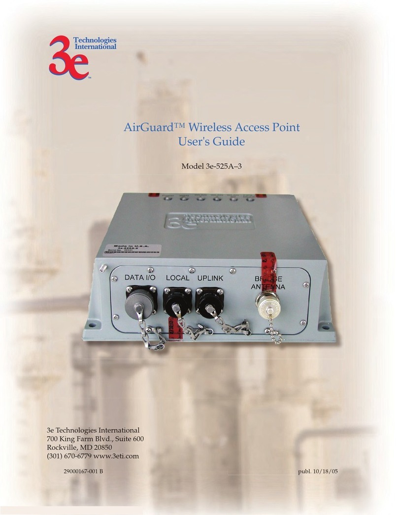
3e Technologies International AirGuard 3e-525C-2 User manual

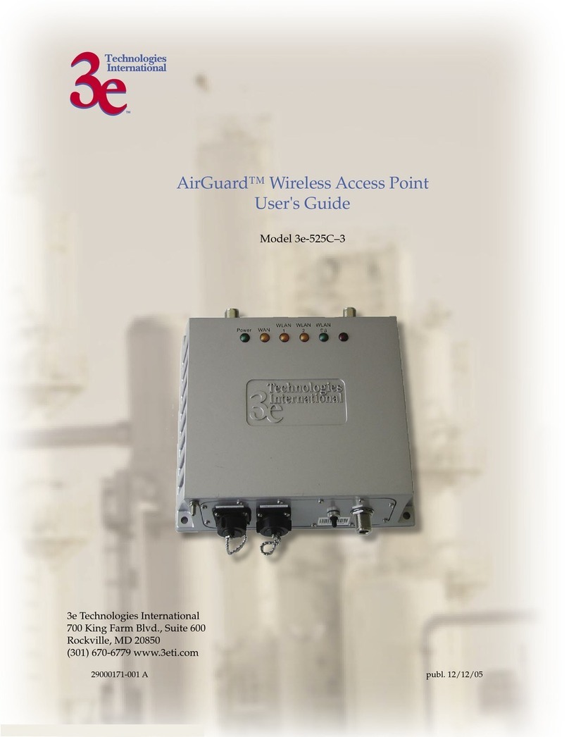
AirGuard™ Wireless Access Point
User's Guide
Model 3e-525C–2
3e Technologies International
700 King Farm Blvd., Suite 600
Rockville, MD 20850
(301) 670-6779 www.3eti.com
29000155-001 A publ. 05/02/05

This page intentionally left blank.

3e Technologies International's
AirGuard™ Wireless Access Point
User's Guide
Model 3e-525C–2

29000155-001 A iii
Copyright © 2005 3e Technologies International. All rights reserved. No part of this documentation
may be reproduced in any form or by any means or to make any derivative work (such as translation,
transformation, or adaptation) without written permission from 3e Technologies International.
3e Technologies International reserves the right to revise this documentation and to make changes in
content from time to time without obligation on the part of 3e Technologies International to provide
notication of such revision or change.
3e Technologies International provides this documentation without warranty, term or condition
of any kind, either implied or expressed, including, but not limited to, the implied warranties,
terms, or conditions of merchantability, satisfactory quality, and tness for a particular purpose.
3e Technologies International may make improvements or changes in the product(s) and/or the
program(s) described in this documentation at any time. Certain features listed may have restricted
availability and/or are subject to change without notice - please conrm material features when
placing orders.
If there is any software or removable media described in this documentation, it is furnished under a
license agreement included with the product as a separate document, in the printed documentation,
or on the removable media in a readable le such as license.txt or the like. If you are unable to locate a
copy of the license, contact 3e Technologies International and a copy will be provided to you.
___________________________________
UNITED STATES GOVERNMENT LEGEND
If you are a United States Government agency, then this documentation and the product described
herein are provided to you subject to the following:
All technical data and computer software are commercial in nature and developed solely at private
expense. Software is delivered as “Commercial Computer Software” as dened in DFARS 252.227-
7014 (June 1995) or as a “commercial item” as dened in FAR 2.101(a) and as such is provided with
only such rights as are provided in 3e Technologies International’s standard commercial license for
the software. Technical data is provided with limited rights only as provided in DFAR 252.227-7015
(Nov 1995) or FAR 52.227-14 (June 1987), whichever is applicable. You agree not to remove or deface
any portion of any legend provided on any licensed program or documentation contained in, or
delivered to you in conjunction with, this User Guide.
___________________________________
3e Technologies International and the 3e Technologies International logo are registered trademarks.
Windows is a registered trademark of Microsoft Corporation. Any other company and product name
mentioned herein is a trademark of the respective company with which they are associated.
___________________________________
EXPORT RESTRICTIONS
This product contains components, software, and/or rmware exported from the United States in
accordance with U. S. export administration regulations. Diversion contrary to U.S. law is prohibited.

29000155-001 A iii
Table of Contents
Chapter 1: Introduction...................................................................................................1
Basic Features .............................................................................................................2
Wireless Basics............................................................................................................2
802.11b.......................................................................................................................3
802.11a .......................................................................................................................3
802.11b/g Mixed......................................................................................................3
802.11 Super G and Turbo A...................................................................................3
Network Conguration ..........................................................................................4
Access Point Congurations..................................................................................4
Possible AP Topologies.........................................................................................4
Bridging ....................................................................................................................5
Data Encryption and Security................................................................................6
SSID ...........................................................................................................................6
WEP ...........................................................................................................................6
WPA with TKIP/ AES-CCMP................................................................................6
AES ............................................................................................................................7
MAC Address Filtering ..........................................................................................7
DHCP Server............................................................................................................7
Operator Authentication and Management ........................................................7
Management...............................................................................................................8
3e–525C–2 Navigation Options ...............................................................................9
Chapter 2: Hardware installation................................................................................11
Preparation for Use..................................................................................................11
Installation Instructions ..........................................................................................12
Minimum System and Component Requirements ............................................12
Connectors and Cabling .........................................................................................13
Bridge Transmit Distance........................................................................................14
Bridge Antenna Location........................................................................................14
Outdoor Protection Kit Installation.......................................................................15
Earth Ground Connection....................................................................................16
Lighnting Arrestor Installation............................................................................16
Antenna Installation................................................................................................17
Sealing Antenna Connections..............................................................................17
Mounting Kit Setup .................................................................................................18
The Indicator Lights..............................................................................................18
Chapter 3: Access Point Conguration ......................................................................21
Introduction ..............................................................................................................21
Preliminary Conguration Steps...........................................................................21
Initial Setup using the “Local” Port ......................................................................22
System Conguration..............................................................................................24
General....................................................................................................................24
WAN........................................................................................................................25
LAN .........................................................................................................................26
Wireless Access Point Conguration ....................................................................27
General....................................................................................................................27
Security ...................................................................................................................30
No Encryption .....................................................................................................30
Static WEP Encryption ......................................................................................31
802.11i and WPA .................................................................................................32
MAC Address Filtering ........................................................................................34
Rogue AP Detection ..............................................................................................35

iv 29000155-0001 A
29000155-001 A v
Advanced................................................................................................................36
Wireless Bridge.........................................................................................................36
Services Settings.......................................................................................................37
DHCP Server..........................................................................................................37
SNMP Agent...........................................................................................................38
User Management....................................................................................................39
List All Users..........................................................................................................39
Add New User .......................................................................................................40
Monitoring/Reports................................................................................................41
System Status .........................................................................................................41
Bridging Status.......................................................................................................42
Bridge Site Map .....................................................................................................43
Wireless Clients......................................................................................................44
Adjacent AP List ....................................................................................................44
DHCP Client List...................................................................................................45
System Log .............................................................................................................45
Web Access Log .....................................................................................................46
Network Activity...................................................................................................46
System Administration ...........................................................................................47
System Upgrade ....................................................................................................47
Firmware Upgrade..............................................................................................47
Local Conguration Upgrade ...........................................................................48
Factory Default ......................................................................................................49
Remote Logging.....................................................................................................49
Reboot .....................................................................................................................50
Utilities....................................................................................................................50
Chapter 4: Wireless Bridge Conguration ................................................................51
Introduction ..............................................................................................................51
Wireless Bridge — General ..................................................................................52
Auto-forming Wireless Bridging ......................................................................52
Manual Bridging .................................................................................................55
Monitoring ...........................................................................................................58
Wireless Bridge — Encryption.............................................................................58
Setting Up Bridging Type .......................................................................................59
Point-to-Point Bridge Conguration ..................................................................59
Point-to-Point Bridging Setup Guide - Manual Mode...................................60
Point-to-Point Bridging Setup Guide - Auto Mode .......................................60
Point-to-Multipoint Bridge Conguration ........................................................64
Point-to-Multipoint Bridging Setup Guide - Manual Mode.........................65
Point-to-Multipoint Bridging Setup Guide - Auto Mode..............................65
Repeater Bridge Conguration ...........................................................................66
Repeater Bridging Setup Guide - Manual Mode............................................66
Repeater Bridging Setup Guide - Auto Mode.................................................67
Chapter 5: Technical Support.......................................................................................69
Manufacturer’s Statement ......................................................................................69
Radio Frequency Interference Requirements.......................................................69
Glossary ........................................................................................................................G-a

iv 29000155-0001 A
29000155-001 A v
SAFETY INFORMATION
Please follow thes guidelines when installing and using the 3e–525C–
2 product.
! WARNING
Warnings must be followed carefully to avoid
bodily injury.
! CAUTION
Cautions must be observed to avoid damage to
your equipment.
NOTE: Notes contain important information about this product.
The following warnings appear in this manual.
! WARNING
Do not attempt to install any outdoor equip-
ment during hazardous conditions such as a
thunderstorm, where lightning could strike the
equipment or installer. Failure to follow this
warning could result in injury or death.

vi 29000155-0001 A
This page intentionally left blank.

3e–525C–2 Wireless Access Point Chapter 1: Introduction
29000155-001 A 1
Chapter 1: Introduction
This manual covers the installation and operation of the 3e Technolo-
gies International’s 3e–525C–2 Wireless Access Point. The 3e–525C–2 is a
ruggedized access point/bridge which is intended for use in industrial
and external environments. It accommodates 802.11a/b/g, 802.11g Super,
and 802.11a Turbo WLAN access and uses Power over Ethernet (PoE) ac-
cess to the Ethernet WAN to eliminate the need for internal access point
power supply units (AC-DC converters) and 110-220V cabling installa-
tions. The wireless LANs can include mobile devices such as handheld
Personal Data Assistants (PDAs), mobile web pads, and wireless laptops.
If encryption is desired for the WLAN, you can select None, Static
WEP, or WPA. WPA uses TKIP or AES-CCMP so you can employ legacy
client WEP cards and still secure the wireless band.
The 3e–525C–2 incorporates Power over Ethernet. The PoE interface
on the 3e–525C–2 is compatible with commercial vendor “injected power”
hub units.
The 3e–525C–2 includes AES cryptographic modules for wireless
encryption and HTTPS/TLS, for secure web communication. In addi-
tion, it contains the capability to use the traditional WEP algorithm, either
as static WEP or managed under WPA. The 3e–525C–2 has an Ethernet
WAN interface for communication to the wired LAN backbone, Ethernet
LAN local port for purposes of initial setup and conguration, and two
wireless AP antennas for communicating on the 802.11a/b/g frequen-
cies. Further, it has the capability for use of an external (remote) antenna,
for bridging, using the 802.11b/g Mixed, 802.11a, 802.11g Super, 802.11a
Turbo frequencies.

3e–525C–2 Wireless Access Point Chapter 1: Introduction
2 29000155-001 A
3e–525C–2 Wireless Access Point Chapter 1: Introduction
29000155-001 A 3
Basic Features
The 3e–525C–2 is housed in a sturdy case which is not meant to be
opened except by an authorized technician for maintenance or repair.
If you wish to reset to factory settings, use the reset function available
through the GUI-based management module or press and hold the reset
button on the front of the unit for 10 seconds.
The 3e–525C–2 is wall-mountable.
It has the following features:
• Ethernet uplink WAN port
• Local Ethernet LAN port (for conguration only)
• Wireless AP with operating range of 2000+ feet
• Wireless Bridge
• Power over Ethernet (PoE)
• Above average temperature range for extreme environments
(with TEC option)
• HTTPS/TLS secure Web
• DHCP client
• Bandwidth control
• Adjustable Radio Power
• MAC address ltering
• Load Balancing
• Rogue AP Detection
The following security modules have been implemented in the 3e–
525C–2 .
• AES (128 bit) for Bridge
• WEP (64, 128, and 152 bit) for AP
• WPA (pre-share key and TKIP/AES-CCMP) for AP
• 802.11i/WPA2 (128 bit) for AP
Wireless Basics
Wireless networking uses electromagnetic radio frequency waves to
transmit and receive data. Communication occurs by establishing radio
links between the wireless access point and devices congured to be part
of the WLAN.
For wireless devices to communicate with the 3e–525C–2 , they must
meet the following conditions:
• The wireless device and wireless access point must have
been congured to recognize each other using the SSID (a
unique ID assigned in setup so that the wireless device is
seen to be part of the network by the 3e–525C–2 );
• Encryption and authentication capabilities and types en-
abled must conform; and
• If MAC ltering is used, the 3e–525C–2 must be congured
to allow the wireless device’s MAC address to associate
(communicate) with the 3e–525C–2 wireless interface.

3e–525C–2 Wireless Access Point Chapter 1: Introduction
2 29000155-001 A
3e–525C–2 Wireless Access Point Chapter 1: Introduction
29000155-001 A 3
802.11b
The IEEE 802.11b standard ratied by IEEE, establishes a stable stan-
dard for compatibility. A user with an 802.11b product can use any brand
of access point with any other brand of client hardware that is built to
the 802.11b standard for basic interconnection. 802.11b devices provide
11 Mbps transmission (with a fallback to 5.5, 2 and 1 Mbps depending on
signal strength) in the 2.4 GHz band.
802.11g
Because 802.11g is backwards-compatible with 802.11b, it is a popular
component in LAN construction. 802.11g broadens 802.11b’s data rates
to 54 Mbps within the 2.4 GHz band using OFDM (orthogonal frequency
division multiplexing) technology.
802.11a
The IEEE 802.11a standard is an extension to 802.11 that applies to
wireless LANs and provides up to 54 Mbps in the 5GHz band. 802.11a
uses an orthogonal frequency division multiplexing encoding scheme
rather than FHSS or DSSS.
802.11b/g Mixed
802.11b/g combines 802.11b and 802.11g data rates to offer a broader
range. In this mode, all transmissions will be at the highest data rate
available.
802.11 Super G and Turbo A
802.11 Super G and 802.11 Turbo A technologies provide speed and
throughput of more than double standard wireless LAN technologies in
networking products such as PCs, access points, routers and PC cards.
It is very helpful to users who require additional bandwidth (over stan-
dard WLAN technologies) that results in higher throughput necessary
for a variety of functions such as: streaming media (video, DVD, MPEG),
VoIP, etc., or for providing multiple users on a single WLAN with optimal
speeds despite network demand.
108 Mbps is the maximum link speed available and the typical MAXI-
MUM end-user throughput ranges from approximately 40 Mbps to 60+
Mbps, depending on application demand and network environment.
NOTE: Super G’s channel bonding feature can signicantly degrade
the performance of neighboring 2.4GHz WLANs that don’t use Super G,
because there isn’t enough room in the 2.4GHz wireless LAN spectrum
for the increased spectrum used by channel bonding. Moreover, Super
G doesn’t check to see if 11b or 11g standards-compliant devices are in
range before using its non-standard techniques.

3e–525C–2 Wireless Access Point Chapter 1: Introduction
4 29000155-001 A
3e–525C–2 Wireless Access Point Chapter 1: Introduction
29000155-001 A 5
Network Conguration
The 3e–525C–2 is an access point with bridging setup capability:
• Access point/Gateway plus:
• Wireless bridging with choice of:
- Point-to-point setup
- Point-to-multipoint setup
- Repeater setup
Bridging actually has more choices, but the above choices are popular
and are discussed later in this user guide (Chapter 4).
Access Point Congurations
When a 3e–525C–2 is used as an access point, IP addresses for wireless
devices are typically assigned by the wired network’s DHCP server. The
wired LAN’s DHCP server assigns addresses dynamically, and the AP
virtually connects wireless users to the host wired network. All wireless
devices connected to the AP are congured on the same subnetwork as
the wired network interface and can be accessed by devices on the wired
network.
Possible AP Topologies
1. An access point can be used as a stand-alone AP without any
connection to a wired network. In this conguration, it simply
provides a stand-alone wireless network for a group of wireless
devices.

3e–525C–2 Wireless Access Point Chapter 1: Introduction
4 29000155-001 A
3e–525C–2 Wireless Access Point Chapter 1: Introduction
29000155-001 A 5
2. There can be multiple APs connected to an existing Ethernet
network to bridge between the wired and wireless environments.
Each AP can operate independently of the other APs on the LAN.
Multiple APs can coexist as separate individual networks at the
same site with a different network ID (SSID).
3. The last and most prevalent use is multiple APs connected to a
wired network and operating off that network’s DHCP server to
provide a wider coverage area for wireless devices, enabling the
devices to “roam” freely about the entire site. The APs have to use
the same SSID. This is the topology of choice today.
Bridging
The wireless bridging function in the 3e–525C–2 allows use as a
bridge, in a number of alternate congurations, including the following
popular congurations:
• Point-to-point bridging of 2 Ethernet Links;
• Point-to-multipoint bridging of several Ethernet links;
• Repeater mode (wireless client to wireless bridge.)

3e–525C–2 Wireless Access Point Chapter 1: Introduction
6 29000155-001 A
3e–525C–2 Wireless Access Point Chapter 1: Introduction
29000155-001 A 7
Data Encryption and Security
The 3e–525C–2 Wireless Access Point includes advanced wireless se-
curity features. Over the AP band, you have a choice of no security, Static
WEP, or WPA. Some level of security is suggested. Static WEP gives you
a choice of 64-bit, 128-bit, or 152-bit encryption. WPA includes the option
of using a WPA pre-shared key or, for the enterprise that has a Radius
Server installed, conguration to use the Radius Server for key manage-
ment with either TKIP or AES-CCMP. Bridging encryption is established
between 3e–525C–2’s and includes use of AES-ECB 128-bit encryption
(approved by the National Institute of Standards and Technology (NIST)
for U.S. Government and DoD agencies).
SSID
The Service Set ID (SSID) is a string used to dene a common roam-
ing domain among multiple wireless access points. Different SSIDs on
access points can enable overlapping wireless networks. The SSID can
act as a basic password without which the client cannot connect to the
network. However, this is easily overridden by allowing the wireless AP
to broadcast the SSID, which means any client can associate with the AP.
SSID broadcasting can be disabled in the 3e–525C–2 setup menus.
WEP
WEP is an older encryption standard but is preferable to no encryp-
tion. If the 3e–525C–2 is congured with WEP encryption, it is compatible
with any 802.11b PC Card congured for WEP.
WPA with TKIP/ AES-CCMP
WPA, an interim standard developed by the WiFi Alliance, combines
several technologies. It includes the use of the 802.1x standard and the
Extensible Authentication Protocol (EAP). In addition, it uses, for encryp-
tion, the Temporal Key Integrity Protocol (TKIP) and WEP 128-bit encryp-
tion keys. Finally, a message integrity check (MIC) is used to prevent an
attacker from capturing and altering or forging data packets. In addition,
it can employ a form of AES called AES-CCMP.
WPA is a subset of the 802.11i standard and is expected to maintain
forward compatibility.

3e–525C–2 Wireless Access Point Chapter 1: Introduction
6 29000155-001 A
3e–525C–2 Wireless Access Point Chapter 1: Introduction
29000155-001 A 7
AES
The Advanced Encryption Standard (AES) was selected by National
Institute of Standards and Technology (NIST) in October 2000 as an up-
grade from the previous DES standard. AES uses a 128-bit block cipher
algorithm and encryption technique for protecting computerized infor-
mation.
The 3e–525C–2 uses AES for the bridging channel.
MAC Address Filtering
The MAC address, short for Media Access Control address, is a hard-
ware address that uniquely identies each node of a network. In IEEE 802
networks, the Data Link Control (DLC) layer of the OSI Reference Model
is divided into two sub-layers: the Logical Link Control (LLC) layer and the
Media Access Control (MAC) layer. The MAC layer interfaces directly with
the network media. Consequently, each type of network media requires a
unique MAC address.
Authentication is the process of proving a client identity. The 3e–
525C–2 access points, if set up to use MAC address ltering, detect an
attempt to connect by a client and compare the client’s MAC address
to those on a predened MAC address lter list. Only client addresses
found on the list are allowed to associate. MAC addresses are pre-as-
signed by the manufacturer for each wireless card.
DHCP Server
The DHCP function is accessible only from the local LAN port to be
used for initial conguration.
Operator Authentication and Management
Authentication mechanisms are used to authenticate an operator ac-
cessing the device and to verify that the operator is authorized to assume
the requested role and perform services within that role.
Access to the management screens for the 3e–525C–2 requires knowl-
edge of the assigned operator ID and Password. The Factory defaults are:
• ID: crypto
• Password: ofcer
The Crypto Ofcer initially installs and congures the 3e–525C–2 after
which the password should be changed from the default password. The
ID and Password are case sensitive.

3e–525C–2 Wireless Access Point Chapter 1: Introduction
8 29000155-001 A
3e–525C–2 Wireless Access Point Chapter 1: Introduction
29000155-001 A 9
Management
After initial setup, maintenance of the system and programming of
security functions are performed by personnel trained in the procedure
using the embedded gui-based management screens.
The next chapter covers the basic procedure for setting up the hard-
ware.

3e–525C–2 Wireless Access Point Chapter 1: Introduction
8 29000155-001 A
3e–525C–2 Wireless Access Point Chapter 1: Introduction
29000155-001 A 9
3e–525C–2 Navigation Options
System Conguration
General
WAN
LAN
Wireless Access Point
General
Security
• None
• Static WEP
• 802.11i and WPA
MAC Address Filtering
Rogue AP Detection
Advanced
Wireless Bridge
General
• Monitoring
Encryption
• AES (128-bit)
MAC Address Filtering
Services Settings
DHCP Server
SNMP Agent
User Management
List All Users
• Edit/Delete
Add New User
Monitoring Reports
System Status
Bridging Status
Bridging Site Map
Wireless Clients
Adjacent AP List
DHCP Client List
System Log
Web Access Log
Network Activities
System Administration
System Upgrade
• Firmware Upgrade
• Local Conguration Upgrade
Factory Default
Remot Logging
Reboot
Utilities

3e–525C–2 Wireless Access Point Chapter 1: Introduction
10 29000155-001 A
This page intentionally left blank.

3e–525C–2 Wireless Access Point Chapter 2: Hardware Installation
29000155-001 A 11
Chapter 2: Hardware installation
Preparation for Use
The 3e Technologies International's 3e–525C–2 Wireless Access Point
requires physical mounting and installation on the site, following a pre-
scribed placement design to ensure optimum operation and roaming.
FCC Regulations require that the 3e–525C–2 be professionally
installed by an installer certied by the National Association of Radio
and Telecommunications Engineers or equivalent institution.
The 3e–525C–2 operates with Power over Ethernet (PoE) which
requires the installation of a separate Power injector which “injects” DC
current into the Cat5 cable. There are two versions of the 3e–525C–2 avail-
able, the standard version with a temperature range of -5 degrees C to +50
degrees C, and there is the extended temperature range product with a
range of -30 degrees C to +70 degrees C. The latter version of the product
employs ThermoElectric Cooler (TEC) technology to extend the product
into the higher temperature environment.
The TEC Technology comes with a price, it requires power to transfer
the heat. Unfortunately, this raises the electric current requirement to 25
watts, beyond the 802.3af specication of 15.4 watts. To ensure that the
3e–525C–2 with TEC option is provided with the power it requires, an
extended range PoE power injector is required such as the 3eTI Model 3e-
POE-1 or Hyperlink Technologies Model BT-CAT5-P1.
The 3e–525C–2 package includes the following items:
• The 3e–525C–2 Wireless Access Point
• 2 attachable 5dBi omni-directional antennas
• 2 meter LAN Ethernet cable (RJ-45 to RJ-45)
• Documentation as PDF les (on CD-ROM)
• Registration and Warranty cards
The following items are options:
• Power Injector, POE, 50W (model 3e-POE-1, p/n 90000831-001)
• Power Cord, POE Injector, European version (p/n 90000832-001)
• Power Cord, POE Injector, UK version (p/n 90000833-001)
• 3 meter antenna extension cable
• Outdoor Protection Kit

3e–525C–2 Wireless Access Point Chapter 2: Hardware Installation
12 29000155-001 A
3e–525C–2 Wireless Access Point Chapter 2: Hardware Installation
29000155-001 A 13
The bridge antenna port is used when conguring the unit to be used
as a bridge. The port uses an omni-directional antenna.
The 3e–525C–2 can be mounted outdoors on a high post to achieve the
best bridge result. If mounted outdoors, the outdoor protection kit must
be used to prevent lightning damage.
To comply with FCC RF exposure compliance requirements, the
antennas used with the 3e–525C–2 must be installed with a mini-
mum separation distance of 20 cm from all persons, and must
not be co-located or operated in conjunction with any other antenna or
transmitter. Installation should be accomplished using the authorized
cables and/or connectors provided with the device or available from the
manufacturer/distributor for use with this device. Changes or modica-
tions not expressly approved by the manufacturer or party responsible for
this FCC compliance could void the user’s authority to operate the equip-
ment.
Installation Instructions
The 3e–525C–2 is intended to be installed as part of a complete wire-
less design solution.
This manual deals only with the 3e–525C–2 device. The purpose of
this chapter is the description of the device and its identiable parts so
that the user is sufciently familiar to interact with the physical unit. Pre-
liminary setup information provided below is intended for information
and instruction of the wireless LAN system administration personnel.
It is intended that the user not open the unit. Any maintenance re-
quired is limited to the external enclosure surface, cable connections, and
to the management software (as described in chapter three through ve)
only. A failed unit should be returned to the manufacturer for mainte-
nance.
Minimum System and Component Requirements
The 3e–525C–2 is designed to be attached to the wall at appropriate
locations. To complete the conguration, you should have at least the fol-
lowing components:
• PCs with one of the following operating systems installed: Win-
dows NT 4.0, Windows 2000 or Windows XP;
• A Wi-Fi compatible 802.11a/b/g device for each computer that
you wish to wirelessly connect to your wireless network. (For
wireless cards, 3eTI recommends that you select the 3e-110 PC
Card with 3e-010F Crypto Client software (sold separately) or
install the 3e-010F software with any compatible PC Card. (If you
will be using WEP, the 3e-010F software is not required);
• Access to at least one laptop or PC with an Ethernet card and
cable that can be used to complete the initial conguration of the
unit.
• A Web browser program (such as Microsoft Internet Explorer 5.5
Table of contents
Other 3e Technologies International Wireless Access Point manuals

3e Technologies International
3e Technologies International AirGuard 3e-525C-3 User manual

3e Technologies International
3e Technologies International 3e-525A User manual

3e Technologies International
3e Technologies International 3e-527A3 User manual

3e Technologies International
3e Technologies International AirGuard 3e-525A-3 User manual

3e Technologies International
3e Technologies International 3e-531AP User manual

3e Technologies International
3e Technologies International 3e-522AW User manual