manuals.online logo
Brands
  1. Home
  2. •
  3. Brands
  4. •
  5. CommScope
  6. •
  7. Wireless Access Point
  8. •
  9. CommScope RUCKUS E510 User manual

CommScope RUCKUS E510 User manual

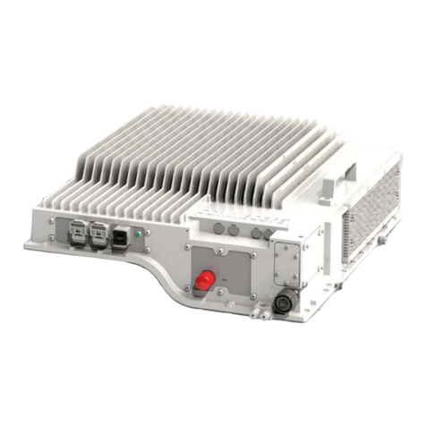
E510 Access Point
AP Module
Quick Setup Guide
The E510 is a modular outdoor Access Point designed for
deployment scenarios where the antenna structure and onboard
AP intelligence must be physically separated.
In addion to this E510 AP Module Quick Setup Guide, the E510
AP also includes the following documents (please refer to the
relevant documents for detailed informaon on other E510
modules):
E510 Component Document
E510 Antenna Module (PN#:
902-2101-0000)
E510 Access Point Antenna
Module Quick Setup Guide
E510 USB Cable (PN#:
902-2003-0000)
E510 Access Point USB Cable
Quick Setup Guide
NOTE: The minimum soware revision for the E510 is
ZoneDirector (ZD) 10.1 or later, or SmartZone (SZ) 3.6 or later,
or standalone AP rmware 108.0 or later.
This Quick Setup Guide provides step-by-step instrucons on how
to eld-install the RUCKUS E510 access point (AP). For detailed
informaon on planning the installaon, performing a site survey
and operang the E510, refer to the RUCKUS Outdoor Access
Point User Guide, available at hps://support.ruckuswireless.com.
WARNING! Only trained and qualied personnel should be
allowed to install, replace, or service this equipment.
WARNING! Installaon of this equipment must comply with
local and naonal electrical codes.
CAUTION! Make sure that you form a 80mm - 130mm (3”-5”)
drip loop in any cable that is aached to the AP or the building.
This will prevent water from running along the cable and
entering the AP or the building where the cable terminates.
CAUTION! Be sure that grounding is available and that it meets
local and naonal electrical codes. For addional lightning
protecon, use lightning rods and lightning arrestors.
CAUTION! Make sure that proper lightning surge protecon
precauons are taken according to local electrical code.
WARNING! RUCKUS strongly recommends that you wear eye
protecon before mounng the AP.
This Guide in Other Languages
•请从以下网站请得请指南的请体中文版 hps://
support.ruckuswireless.com.
•Vous trouverez la version française de ce guide à l'adresse
suivante hps://support.ruckuswireless.com.
•このガイドの日本語版は hps://support.ruckuswireless.com
でご覧ください。
•请 请请请请 请请请 请请请 请 请请请 (hps://support.ruckuswireless.com) 请请
请请请请请 请请请请.
•Veja a versão em português (Brasil) deste guia em hps://
support.ruckuswireless.com.
•Puede ver la versión en español (América Lana) de esta guía
en hps://support.ruckuswireless.com.
Before You Begin
Before deploying RUCKUS products, please check for the latest
soware and the release documentaon.
•Release Notes and other user documentaon are available at
hp://support.ruckuswireless.com/documents.
•Soware upgrades are available at hp://
support.ruckuswireless.com/soware.
•Soware license and limited warranty informaon are available
at hp://support.ruckuswireless.com/warranty.
Before deploying your RUCKUS Access Point, verify that all
items listed in Package Contents are included in the package. If
any item is damaged or missing, nofy your authorized RUCKUS
sales representave. Also, make sure that you have the
required hardware and tools.
Required Hardware and Tools
•Torque wrench or torque screwdriver with sockets, or SMA
torque wrench, for cable connecons
•T10 Security Torx screwdriver/bit for reset buon access
•Mounng bracket (purchased separately) for pole mounng
•Customer-supplied mounng bracket for DIN rail mounng
•Electric drill with drill bits and customer-supplied wall anchors,
at washers, and hex nuts for at-surface mounng
AP Module Package Contents
The E510 AP Module installaon package includes all of the
following:
•E510 Embedded Access Point Module
•Service Level Agreement/Limited Warranty Statement
•Declaraon of Conformity
•Regulatory Statement
•RUCKUS AP Geng Started Guide
•This Quick Setup Guide
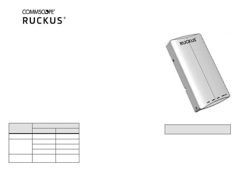
FIGURE 1 E510 AP Module
Purchased Separately
The E510 requires an Antenna Cable Kit and Antenna Module
(RUCKUS or third-party RF cables) to be purchased separately.
NOTE: BeamFlex is not supported when using third-party RF
cables.
Antenna Module
The E510 Antenna Module (RUCKUS PN# 902-2101-0000) consists
of one vercally-polarized and one horizontally-polarized antenna
per band. Refer to the E510 Antenna Module Quick Setup Guide
for more informaon.
Antenna Cable Kit
Ruckus provides three dierent cable kits with dierent length
cables. Each kit contains two RF coaxial cables and one Control
cable. The RF cables are used to connect the AP Module to the
Antenna Module using two RP-SMA connectors (each dual-band/
single chain).
•902-2000-0000 E510 Antenna Cable (60 cm length)
Copyright © 2020 CommScope, Inc. All rights reserved. Page 1 of 4
Published June 2020, Part Number 800-71577-001 Rev D
•902-2001-0000 E510 Antenna Cable (150 cm length)
•902-2002-0000 E510 Antenna Cable (300 cm length)
CAUTION! If third-party RF cables are used, the customer is
responsible for entering the correct signal loss prole /
antenna gain in the SmartZone GUI.
Mounng Bracket
The E510 AP Module Mounng Bracket (RUCKUS PN#
902-2004-0000) must be purchased separately for mounng the
AP Module to a pole. The pole mounng bracket kit includes the
following:
•Pole mount bracket
•3 M4x8mm bracket screws with built-in lock washers and at
washers
•4 metal pole clamps
M8 and M12 Connectors
If third-party Ethernet or DC power cables are used, the installer
must ensure the proper cable connectors are used. The following
are examples of third-party cable connectors that can be used
with the E510:
•M12 X-coded 8 posion PoE connector: hps://www.te.com/
usa-en/product-2120952-1.html
•M8 A-coded 3 posion connector: hps://www.te.com/usa-en/
product-T4010008031-000.html
Mounng Instrucons
Mounng Scenarios
The E510 is designed for embedded mounng into third-party
structures such as light poles, light xtures, street furniture,
railway carriages and track side installaons.
Surface Mounng
The AP Module supports mounng on a at surface into which
holes can be drilled.
Use customer-supplied hardware to mount the AP Module to a
at surface.
FIGURE 2 E510 AP Module at surface mounng anges
Pole Mounng
The E510 AP Module can be mounted on a pole with the E510 AP
Module Mounng Bracket (PN# 902-2004-0000).
NOTE: The included hose clamps can support a pole diameter
up to 120mm, when daisy-chained together.
1. Aach the mounng bracket to the AP Module using the
three M4 bracket screws with built-in at washers and lock
washers included in the bracket kit. Torque screws to 20 in-
lbs (2.26 Nm).
NOTE: The AP Module can be mounted either at to the
pole or side-mounted. The bracket provides holes to
accommodate both scenarios. Side mounng uses three
screws and at mounng uses two screws.
FIGURE 3 Aaching the bracket to the side of the AP
FIGURE 4 Aaching the bracket to the back of the AP
2. Use the two metal pole clamps to aach the bracket to the
pole. Tighten pole clamp screws to 27 in-lbs. (3.05 Nm).
Copyright © 2020 CommScope, Inc. All rights reserved. Page 2 of 4
Published June 2020, Part Number 800-71577-001 Rev D
FIGURE 5 AP Module pole mounng - side
FIGURE 6 AP Module pole mounng - at
DIN Rail Mounng
The AP Module supports mounng onto DIN Rail brackets via a
separate third-party bracket accessory.
Connecng the AP Module to the Antenna Module
When a RUCKUS Beamex antenna, such as 902-2101-0000, is
used, the E510 AP Module must be connected to the Antenna
Module using two RF cables and one Control Cable.
NOTE: For Antenna Mounng and Orientaon, please refer to
the E510 Antenna Module Quick Setup Guide.
The E510 AP module has two RP-SMA connectors for antenna RF
cables to connect with the external antenna module. The 2.4 GHz
and 5 GHz Wi-Fi RF signals are carried between the AP Module
and Antenna Module using the two SMA cables.
The length of the cables depends on the needs of the installaon,
and cables are therefore purchased separately to suit the
parcular deployment.
TABLE 1 Antenna loss by cable length
Cable Length [m] 2.4 GHz Loss
[dB]
5 GHz Loss
[dB]
902-2000-000
0
0.6 0.5 1
902-2001-000
0
1.5 1 1.5
902-2002-000
0
323
Please refer to the E510 Antenna Module Quick Setup Guide for
antenna cable details.
1. Connect the antenna cables to the ANT1 and ANT2
connectors on the AP Module and the Antenna Module
respecvely.
FIGURE 7 Connect the AP Module to the Antenna Module
WARNING! Be sure that you connect the correct antenna
cable to the correct port (ANT1 to ANT1, ANT2 to ANT2).
Do NOT connect ANT1 to ANT2.
2. Using a torque wrench/screwdriver with an SMA (5/16)
adapter, ghten the antenna cable connectors to 4 in-lbs.
(0.45 N.m).
3. Connect the M12 antenna Control Cable to the M12
connector (female) on the AP module.
4. Connect the other end of the M12 antenna Control Cable to
the M12 connector (male) on the Antenna module.
FIGURE 8 E510 Antenna Module connectors
NOTE: The Control Cable has one male and one female
connector to prevent installing the cable incorrectly.
Power Input
The E510 can accommodate two sources of power, 802.3af PoE
power or 12V-48V DC.
The E510 can be powered by 802.3af PoE switch or Ruckus-
supplied PoE injector.
Alternately, power can be supplied from a DC power source using
the M8 connector.
When both power sources exist, 12-48V DC takes priority over
PoE Power.
NOTE: For informaon on the recommended M8 cable
connectors for the E510, refer to the M8 and M12 Connectors
secon in Purchased Separately, above.
Copyright © 2020 CommScope, Inc. All rights reserved. Page 3 of 4
Published June 2020, Part Number 800-71577-001 Rev D
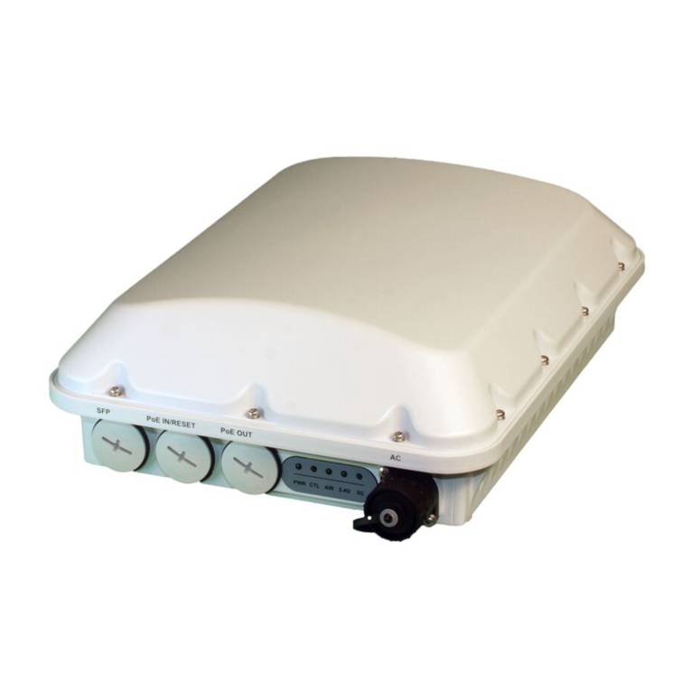
FIGURE 9 E510 DC power and PoE In ports
Connecng the Ethernet Cable
The E510 has one 10/100/1000 PoE Ethernet port with M12
weatherproof connector.
Connect the Ethernet cable to a 802.3af-compliant PoE switch or
injector to provide both power and network connecvity.
NOTE: For informaon on the recommended M12 cable
connectors for the E510, refer to the M8 and M12 Connectors
secon in Purchased Separately, above.
Factory Reset Buon
The Reset buon can be accessed by removing the Torx screw
labeled RESET.
Use a T10 Security Torx screwdriver or bit to remove the Torx
screw covering the Reset buon.
Insert a pin or similar object less than 2.5 mm in diameter into the
reset hole to reboot or factory reset the device.
Press and release the reset buon to reboot the AP. Press and
hold the reset buon for 4+ seconds to restore to factory
defaults.
FIGURE 10 Remove Torx screw to access Reset buon
CAUTION! Remember to replace the Torx screw covering the
Reset buon aer use. Insert the screw and torque to 4 in-lbs.
(0.45 Nm).
USB Port
E510 has one USB 2.0 port as an M8 IP67 connector (Female).
This port provides both a data connecon and power output for
an IoT device such as a BLE Smart Beacon or ZigBee dongle.
A USB cable with an M8 connector at one end and a USB 2.0
Type-A connector at the other end can be aached to the female
M8 connector on the E510 AP module.
A USB Module Accessory can be purchased separately, and comes
with a 3m USB cable (RUCKUS PN# 902-2003-0000).
NOTE: Please refer to the E510 USB Cable Quick Setup Guide
for more informaon.
FIGURE 11 E510 USB port, Control cable and Antenna cable
connectors
For More Informaon
For informaon on how to congure and manage the AP, refer to
the RUCKUS Access Point User Guide, available from hps://
support.ruckuswireless.com.
RUCKUS WIRELESS, Inc. is a wholly owned subsidiary of
CommScope, Inc.
© 2020 CommScope, Inc. All rights reserved.
ARRIS, the ARRIS logo, COMMSCOPE, RUCKUS, RUCKUS WIRELESS, the Ruckus
logo, and the Big Dog design are trademarks of CommScope, Inc. and/or its
aliates. Wi-Fi Alliance, Wi-Fi, the Wi-Fi logo, Wi-Fi Cered, the Wi-Fi
CERTIFIED logo, Wi-Fi Protected Access, the Wi-Fi Protected Setup logo, Wi-Fi
Protected Setup, Wi-Fi Mulmedia and WPA2 and WMM are trademarks or
registered trademarks of Wi-Fi Alliance. All other trademarks are the property of
their respecve owners.
Copyright © 2020 CommScope, Inc. All rights reserved. Page 4 of 4
Published June 2020, Part Number 800-71577-001 Rev D
Other CommScope Wireless Access Point manuals

CommScope T750SE User manual

CommScope

CommScope T750SE User manual

CommScope RUCKUS R550p User manual

CommScope

CommScope RUCKUS R550p User manual

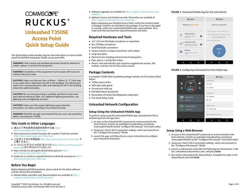
CommScope RUCKUS Unleashed T350SE User manual

CommScope

CommScope RUCKUS Unleashed T350SE User manual

CommScope ERA CAP L2 18/21/ 23T/26 F-DC User manual

CommScope

CommScope ERA CAP L2 18/21/ 23T/26 F-DC User manual

CommScope RUCKUS R350 User manual

CommScope

CommScope RUCKUS R350 User manual

CommScope ION E Series User manual

CommScope

CommScope ION E Series User manual

CommScope RUCKUS R550 User manual

CommScope

CommScope RUCKUS R550 User manual

CommScope Ruckus Unleashed R650p User manual

CommScope

CommScope Ruckus Unleashed R650p User manual

CommScope RUCKUS R760 User manual

CommScope

CommScope RUCKUS R760 User manual

CommScope RUCKUS T350c User manual

CommScope

CommScope RUCKUS T350c User manual

CommScope RUCKUS H550 User manual

CommScope

CommScope RUCKUS H550 User manual

CommScope RUCKUS Unleashed R750 User manual

CommScope

CommScope RUCKUS Unleashed R750 User manual

CommScope RUCKUS H350 User manual

CommScope

CommScope RUCKUS H350 User manual

CommScope ERA CAP M2 User manual

CommScope

CommScope ERA CAP M2 User manual

CommScope ERA CAP L2 18/21/ 23T/26 F-DC User manual

CommScope

CommScope ERA CAP L2 18/21/ 23T/26 F-DC User manual

CommScope Era User manual

CommScope

CommScope Era User manual

CommScope RUCKUS User manual

CommScope

CommScope RUCKUS User manual

CommScope Era M0201AKB_uc User manual

CommScope

CommScope Era M0201AKB_uc User manual

CommScope RUCKUS Unleashed H550 User manual

CommScope

CommScope RUCKUS Unleashed H550 User manual

CommScope RUCKUS Unleashed T350c User manual

CommScope

CommScope RUCKUS Unleashed T350c User manual

CommScope SYSTIMAX InstaPATCH 360 Guide

CommScope

CommScope SYSTIMAX InstaPATCH 360 Guide

CommScope Era CAP M 9 User manual

CommScope

CommScope Era CAP M 9 User manual

CommScope RUCKUS H350 User manual

CommScope

CommScope RUCKUS H350 User manual

CommScope SYSTIMAX AirSPEED AP541 User manual

CommScope

CommScope SYSTIMAX AirSPEED AP541 User manual

Popular Wireless Access Point manuals by other brands

Westermo Ibex-RT-220 Series user guide

Westermo

Westermo Ibex-RT-220 Series user guide

Meru Networks AP1014i installation guide

Meru Networks

Meru Networks AP1014i installation guide

TP-Link TL-WA7110ND user guide

TP-Link

TP-Link TL-WA7110ND user guide

Korenix JetWave 2640 quick start guide

Korenix

Korenix JetWave 2640 quick start guide

Madge Networks 802.11b user guide

Madge Networks

Madge Networks 802.11b user guide

NETGEAR ProSafe WNAP320 Reference manual

NETGEAR

NETGEAR ProSafe WNAP320 Reference manual

Proxim ORINOCO AP-2000 user guide

Proxim

Proxim ORINOCO AP-2000 user guide

D-Link DWL_7100 manual

D-Link

D-Link DWL_7100 manual

Moxa Technologies AirWorks AWK-3131-M12-RCC Quick installation guide

Moxa Technologies

Moxa Technologies AirWorks AWK-3131-M12-RCC Quick installation guide

H3C WA6636 installation guide

H3C

H3C WA6636 installation guide

ZyXEL Communications NWA1123-NI quick start guide

ZyXEL Communications

ZyXEL Communications NWA1123-NI quick start guide

MikroTik RouterBOARD OmniTIK U-5HnD Quick setup guide

MikroTik

MikroTik RouterBOARD OmniTIK U-5HnD Quick setup guide

ActionTec MyWirelessTV 2 user manual

ActionTec

ActionTec MyWirelessTV 2 user manual

SIGNIFY Trulifi 6002 user manual

SIGNIFY

SIGNIFY Trulifi 6002 user manual

NETGEAR WG302 - 802.11g ProSafe Wireless Access... Reference manual

NETGEAR

NETGEAR WG302 - 802.11g ProSafe Wireless Access... Reference manual

TRENDnet TPL-110AP - 125Mbps 802.11g Wireless Powerline Access... Frequently asked questions

TRENDnet

TRENDnet TPL-110AP - 125Mbps 802.11g Wireless Powerline Access... Frequently asked questions

TP-Link TL-WA901N user guide

TP-Link

TP-Link TL-WA901N user guide

Ubiquiti airFiber AF-11 quick start guide

Ubiquiti

Ubiquiti airFiber AF-11 quick start guide

manuals.online logo
manuals.online logoBrands
  • About & Mission
  • Contact us
  • Privacy Policy
  • Terms and Conditions

Copyright 2025 Manuals.Online. All Rights Reserved.