3M-Matic S867 L-Clip Applicator Datasheet

Instructions and Parts List
Purpose of Kit
TheU-ClipModificationKitisdesignedtobuffa
standardL-clipdowntoformaU-shapedtape clip
aroundthe edgeof thinnercartonswhen usedon the
S867 or S857 L-Clip Applicators. U-clips can be
applied to cartons from 1/4 inch [6.4 mm] thick to 2
inches [50 mm] thick. Refer to the Specifications
section.
P/N 70-0708-6798-4
S867/S857 U-Clip
Modification Kit
Specifications
Tape length applied, total: 4 1/2 inches [115 mm]
U-cliptapelengths:
Bottom of carton: 2 1/4 ± 1/8 inch
[55 mm ± 3.2 mm]
Endof carton: Thicknessofcarton
Top ofcarton: 2 1/4 [55 mm], minus
thickness of carton
Carton size capacity:
1/4 inch [6.4 mm] minimum
2 inch [50 mm] maximum
Contents of Kit
Quantity Description
1 BuffingAssembly
1 BuffingSleeve
2 Capscrew, Soc. Hd., 10-24 x 1/2 Lg
2 Washer, Plain, Type A, #10
1 Instructions and Parts List
3M-Mati
c
TM
For use on 3M-Matic™
S867 L-Clip Applicator, Type 10500
S857 L-Clip Applicator, Type 29500

Installation
Figure 1—Replace Buffing Sleeves
1. Pullbuffingassemblyupthroughfrontofmachine
andreplaceexistingupperbuffingsleeveswith
thenewlargerdiameterupperbuffingsleeve
supplied with this kit. See Figure 1.
Important: Be sure to replace the sleeve on the
UPPER buffing arm, NOT on the lower buffing
arm.
2. TheS867/S857"U"ClipModificationKitrequires
four tapped holes in the top surface of the L-clip
applicator. Some older S857 applicators do not
have these holes. If not, the holes must be
located, drilled, and tapped. Use the enclosed
hole template and follow Steps A–E on the
template. If your machine already has these
holes, skip this step.
3. Attach mounting bracket to the front edge of the
L-clip applicator with two 10-24 x 1/2 capscrews
and plain washers as shown in Figure 2.
4. RemovetheT-fittingfromendofpolytubingon
modification kit. Push end of fitting in to release
tubing. See Figure 2.
5. Unlatchand open right side cover on the L-clip
applicator. Feed poly tubing through hole in left
sideofapplicator(Figure3A)androutebehind
existingtubingtowardsback ofapplicator (Figure
3B).
Note: Besuretubingdoesnotinterfere with any
moving parts of applicator. The 32.5" tube must
be cut to 13.5" length if installed on a S857.
Figure 2—Attach Mounting Bracket
Figure 3—Install Poly Tubing
WARNING
•To reduce the risk associated with
mechanical hazards:
−Turnairsupplyoffanddisconnectbefore
performinganyadjustments,maintenance,or
servicingthemachineortapingheads.
•To reduce the risk associated with sharp
blade hazards:
−Keephandsandfingersawayfromtapecutoff
bladesunderorangebladeguards.The
bladesareextremelysharp.

1. TurntheS867applicatormainairon/offvalveto
On.
2. Turnthe U-clip attachment ballvalvetoOn so
thatthe valvehandle aligns withthe tubing.
3. Hold down and push carton against applicator
box paddle to apply a U-clip. The applicator
applies an L-clip of tape to bottom and edge of
carton. The U-clip attachment automatically
buffs the top leg of the tape down onto the top of
the carton.
4. ToconvertapplicatorbacktoL-clipoperation,
turnoffU-clipattachmentballvalve,unscrewand
removemountingbracket and attach to left side
of the applicator for storage as shown in Figure 6.
Installation (Continued)
Figure 6—Remove Mounting Bracket
6. Cutairlinenumber17ontheflowcontrolvalve
approximately 1 inch [25 mm] down from the L-
fitting as shown in Figure 4. Note that the
position of air line 17 on the S867 is different than
its position on the S857.
7. Reinstall the T-fitting as shown in Figure 5 by
pushing the tubing into the fitting as far as it will
go.
8. Closeand latch side coveron the applicator and
connect main the air supply line to the applicator.
9. TurnontheL-clipapplicatorairvalvetoOn. Turn
the U-clip attachment ball valve to On so that the
valvehandle alignswiththe tubing. Checkforair
leaks.
Operation
Figure 5—Reinstall T-Fitting
Figure 4—Air Line #17

Ref. Part
No. Number Description Qty.
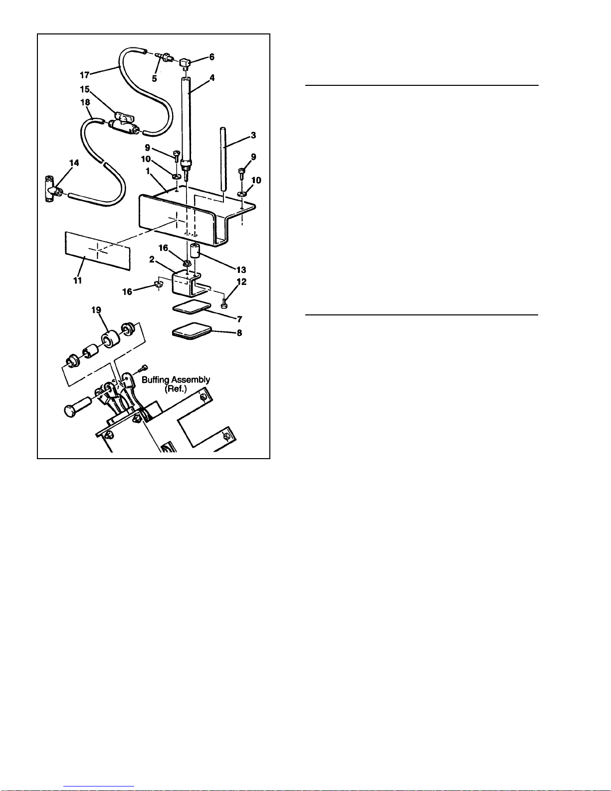
1 78-8119-6882-1 Bracket, Mounting 1
2 78-8119-6883-9 Bracket, Buffing 1
3 78-8119-6884-7 Shaft 1
4 26-1014-4181-9 Cylinder, Air, 7/16" Bore, 1
Bimba #013-NR
5 26-1014-4182-7 Fitting, Barbed, #10-32, 1
Bimba #D-3229-A
6 26-1014-6599-0 Fitting, Street Ell, #10-32 1
7 78-8119-6919-1 Pad, Buffing, Upper 1
8 78-8119-6918-3 Buffing Pad Assembly, Lower 1
9 26-1004-6031-5 Screw, Cap, Soc Hd, 10-24 x 1/2 Lg. 2
10 26-1000-4442-4 Washer, Plain, Type A, #10 2
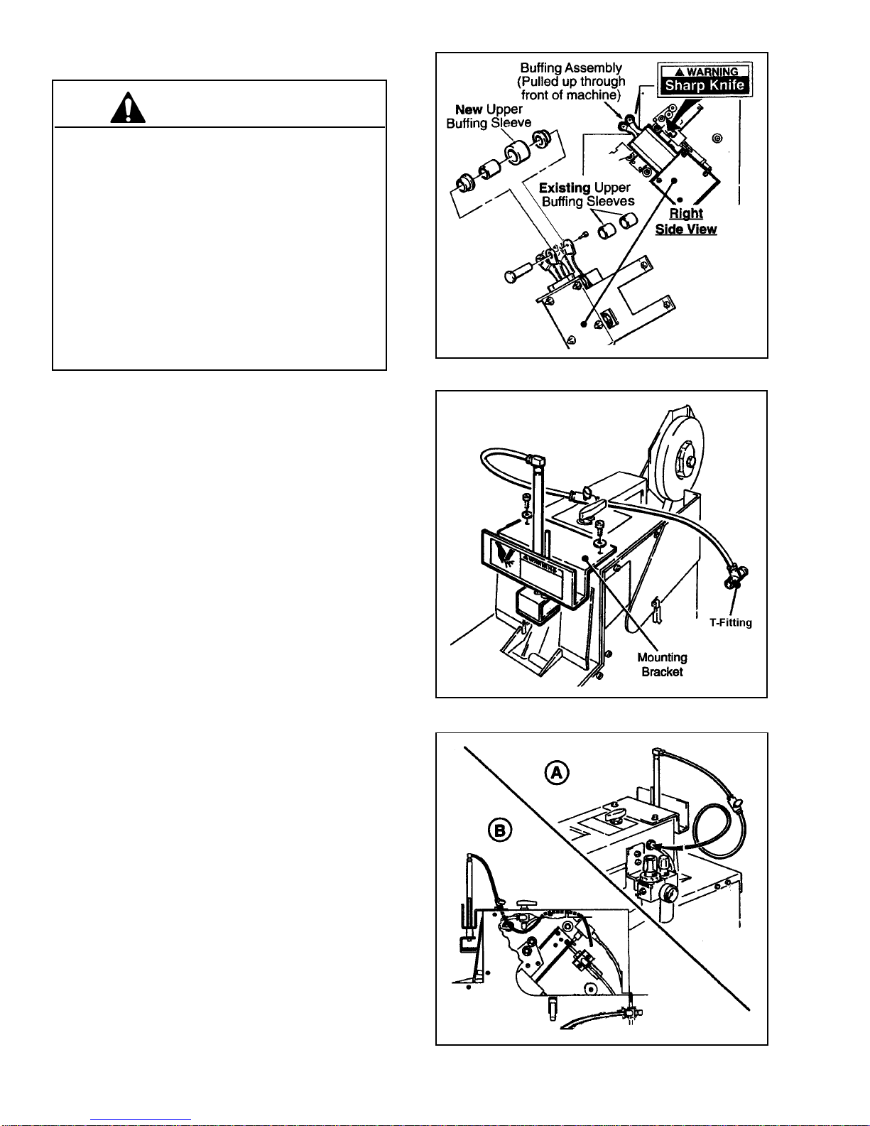
11 78-8119-6594-2 Label, Warning, Sharp Knife Rollers 1
12 18-3172-8216-0 Screw, Cap, Soc Hd, 8-32 x 1/2 Lg. 1
13 78-8119-6935-7 Stop, Buffer 1
14 26-1014-6602-2 Tee, Union, 1/4 Polyflo
Legris #3104-56-00 1
15 26-1014-6963-8 Valve, Ball, 1/4-1/4 Polyflo
Pisco #BVU20-1/4-1/4 1
16 26-1014-6970-3 Nut, Hex Flange, 10-32 2
17 78-8119-6936-5 Tube, Poly-Flo, 8.5 In. Lg. 1
18 78-8122-6541-7 Tube, Poly-Flo, 32.5 In. Lg. 1
19 78-8122-6664-7 Buffing Sleeve 1
Replacement Parts List
Figure 7—Replacement Parts Illustration
3M Industrial Adhesives and Tapes Division
3M Center, Building 220-4E-01
St. Paul, MN 55144-1000
“3M-Matic” is a trademark of 3M,
St. Paul, Minnesota 55144-1000
Printed in U.S.A.
© 3M 2007 44-0009-1957-9(C)
How To Order Replacement Parts
1. Refer to Parts Illustration Figure 7 to find part needed
and reference number.
2. Refer to parts list for correct part number.
3. Order by part number, description, kit name, and kit
part number.
4. Replacement parts and part prices available direct
from:
3M/Tape Dispenser Parts
241 Venture Drive
Amery, WI 54001-1325
Minimum billing on parts orders will be $25.00.
Replacement part prices available on request. $10.00
restocking charge per invoice on returned parts.
Outside the U.S., contact the local 3M subsidiary for
parts information.
800-344-9883
Fax: 715-268-8153
33
33
3
EquipmentWarrantyandLimitedRemedy:THEFOLLOWINGWARRANTY ISMADEINLIEUOFALL OTHERWARRANTIES,EXPRESS
ORIMPLIED,INCLUDING,BUTNOTLIMITEDTO,ANYIMPLIEDWARRANTYOFMERCHANTABILITYORFITNESSFORAPARTICULAR
PURPOSEANDANYIMPLIEDWARRANTY ARISING OUT OF A COURSE OF DEALING, CUSTOMORUSAGEOFTRADE:
3M sells its 3M-Matic™ P/N 70-0708-6798 S867/S857 U-Clip Modification Kit with the following warranties:
Limitation of Liability: Except where prohibited by law, 3M and seller will not be liable for any loss or damage arising from this 3M equipment, whether direct,
indirect, special, incidental, orconsequential, regardless of the legal theoryasserted, including breach of warranty, breach ofcontract, negligence, or strict liability.
Note: The foregoing Equipment Warranty and Limited Remedy and Limitation of Liability may be changed only by a written agreement signed by authorized
representatives of 3M and seller.
All parts will be free from defects in material and manufacture for ninety (90) days after delivery.
If any part is defective within this warranty period, your exclusive remedy and 3M’s and seller’s sole obligation shall be, at 3M’s option, to repair or replace
the part. 3M must receive actual notice of any alleged defect within a reasonable time after it is discovered, but in no event shall 3M have any obligation
under this warranty unless it receives such notice within five (5) business days after the expiration of the warranty period. All notices required hereunder
shall be given to 3M solely through the 3M-Matic™ Helpline (800-328-1390). To be entitled to repair or replacement as provided under this warranty, the part
must be returned as directed by 3M to its factory or other authorized service station designated by 3M. If 3M is unable to repair or replace the part within
a reasonable time after receipt thereof, 3M, at its option, will replace the equipment or refund the purchase price. 3M shall have no obligation to provide or
pay for the labor required to remove any part or equipment or to install the repaired or replacement part or equipment. 3M shall have no obligation to repair
orreplacethose parts failing due to normal wear, inadequateor improper maintenance, inadequatecleaning, non-lubrication, improper operating environment,
improper utilities, operator error or misuse, alteration or modification, mishandling, lack of reasonable care, or due to any accidental cause.

Hole Location Template
Center punch four (4) holes indicated by
Remove template and drill four (4)
0.1495 (#25 drill) holes.
Tap four (4) holes with 10-24 tap.
Cut out and remove this circle for
clearance around on/off valve.
Lineup these twoedges of templatewith front and
left side of S867 applicator and secure template to
applicatorwith masking tape.
A
B
C
D
E
– Left Side –
– Front –
– Right Side of Applicator –

Hole Location Template
(See other side)
This manual suits for next models
1
Table of contents
Popular Food Saver manuals by other brands

Braun
Braun MultiQuick MR 5000 FS owner's manual

HUSLOG
HUSLOG 613104 user manual

ChromTech
ChromTech Porvair Miniseal II manual

Van Der Stahl
Van Der Stahl V-460G Series operating instructions

CASO DESIGN
CASO DESIGN VG 3000 Original operating manual

FoodSaver
FoodSaver Pro Sport GameSaver Vac1500 user manual