3M PROTECTA 3503882 User manual

© 3M 2023
USER INSTRUCTIONS
5908123 REv. B
ULTRA-LOK
SELF-RETRACTING DEVICES
;For identication of product codes, refer to Table 1. See “Table 1 - Product Specications” for more product information.
Figure 1 - Product Overview
1 2 3 4A
B
WL
X
Model Connectors Housing
Size Lifeline Extended Length (X) Working Length (WL)
A B
3503882 1 --- C2 Size A SS1 50 ft. (15.2 m) 49 ft. (14.9 m)
3503883 1 --- C3 Size A SR1 50 ft. (15.2 m) 49 ft. (14.9 m)
3503884 1 --- C2 Size B SS1 85 ft. (25.9 m) 84 ft. (25.6 m)
3503885 2 --- C3 Size B GS2 55 ft. (16.8 m) 53 ft. (16.2 m)
3503886 3 C1 C3 Size C GS1 50 ft. (15.2 m) 49 ft. (14.9 m)
3503887 3 C1 C2 Size C SS1 50 ft. (15.2 m) 49 ft. (14.9 m)
3503888 4 --- C3 Size D GS1 50 ft. (15.2 m) 49 ft. (14.9 m)
3503889 4 --- C2 Size D SS1 50 ft. (15.2 m) 49 ft. (14.9 m)
OSHA 29 CFR 1910.140
OSHA 29 CFR 1926.502

FORM NO: 5908239 REV: E 2
SAFETY INFORMATION
Please read, understand, and follow all safety information contained in these instructions, prior to the use of this product. FAILURE TO DO SO
COULD RESULT IN SERIOUS INJURY OR DEATH.
These instructions must be provided to the user of the equipment. Retain these instructions for future reference.
Intended Use:
This product is used as part of a complete Fall Protection system.
Use in any other application including, but not limited to, material handling, recreational or sports-related activities, or other activities not described in these
instructions, is not approved by 3M and could result in serious injury or death.
This product is only to be used by trained users in workplace applications.
!WARNING
This product is used as part of a complete Fall Protection system. All users must be fully trained in the safe installation and operation of their complete Fall
Protection system. Misuse of this product could result in serious injury or death. For proper selection, operation, installation, maintenance, and service,
refer to all instruction manuals and manufacturer recommendations. For more information, see your supervisor or contact 3M Technical Services.
• To reduce the risks associated with using a Self-Retracting Device which, if not avoided, could result in serious injury or death:
- Inspect the product before each use and after any fall event, in accordance with the procedures specied in these instructions.
- If inspection reveals an unsafe or defective condition, remove the product from service immediately and clearly tag it “DO NOT USE”. Destroy or
repair the product as required by these instructions.
- Any product that has been subject to fall arrest or impact force must be immediately removed from service. Destroy or repair the product as
required by these instructions.
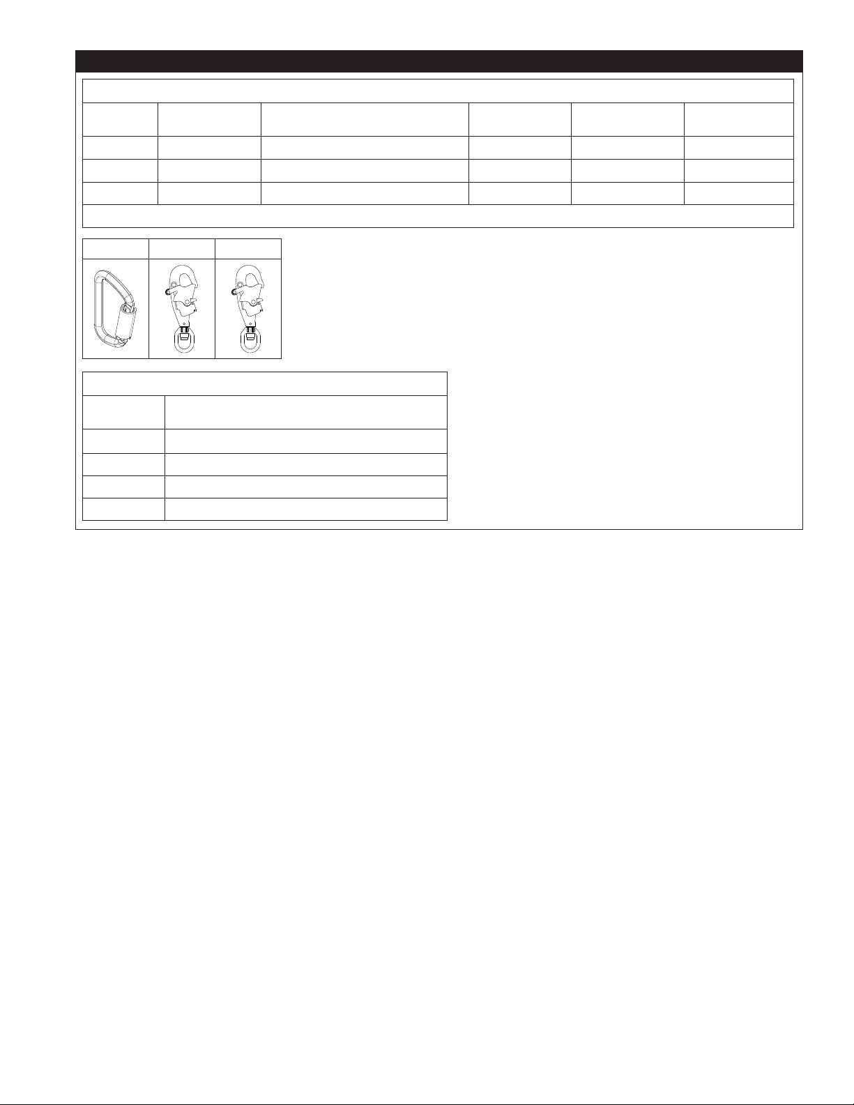
- Ensure that Fall Protection systems assembled from components made by different manufacturers are compatible and meet all applicable Fall
Protection regulations, standards, or requirements. Always consult a Competent or Qualied Person before using these systems.
- Ensure the product is kept free from all hazards including, but not limited to: entanglement with users, other workers, moving machinery, other
surrounding objects, or impact from overhead objects that could fall onto the product or users.
- Do not twist, tie, knot, or allow slack in the lifeline.
- Avoid trip hazards with legs of the lifeline. Attach any unused lifeline legs to the lanyard parking elements on your full body harness, if present.
- Do not exceed the number of allowable users specied in these instructions.
- Do not use in applications that have an obstructed fall path. A clear path is required to lock the SRD. Working on slowly shifting materials (e.g. sand
or grain), or within conned spaces or limited spaces, may not allow the worker to reach sufcient speed to lock the SRD.
- Avoid sudden or quick movements during work operation because this may cause the SRD to unintentionally lock.
- Use caution when installing, using, or moving the product as moving parts may create pinch points.
- Use appropriate edge protection when the product may contact sharp edges or abrasive surfaces.
- Ensure the product is congured and installed properly for safe operation as described in these instructions.
• To reduce the risks associated with working at height which, if not avoided, could result in serious injury or death:
- Your health and physical condition must allow you to safely work at height and to withstand all forces associated with a fall arrest event. Consult
your doctor if you have questions regarding your ability to use this equipment.
- Never exceed allowable capacity of your Fall Protection equipment.
- Never exceed the maximum free fall distance specied for your Fall Protection equipment.
- Do not use any Fall Protection equipment that fails inspection, or if you have concerns about the use or suitability of the equipment. Contact 3M
Technical Services with any questions.
- Some subsystem and component combinations may interfere with the operation of this equipment. Only use compatible connections. Contact 3M
Technical Services before using this equipment in combination with components or subsystems other than those described in these instructions.
- Use extra precautions when working around moving machinery, electrical hazards, extreme temperatures, chemical hazards, explosive or toxic
gases, sharp edges, abrasive surfaces, or below overhead materials that could fall onto you or your Fall Protection equipment.
- Ensure use of your product is rated for the hazards present in your work environment.
- Ensure there is sufcient fall clearance when working at height.
- Never modify or alter your Fall Protection equipment. Only 3M, or persons authorized in writing by 3M, may make repairs to 3M equipment.
- Before using Fall Protection equipment, ensure a written rescue plan is in place to provide prompt rescue if a fall incident occurs.
- If a fall incident occurs, immediately seek medical attention for the fallen worker.
- Only use a full body harness for Fall Arrest applications. Do not use a body belt.
- Minimize swing falls by working as directly below the anchorage point as possible.
- A secondary Fall Protection system must be used when training with this product. Trainees must not be exposed to an unintended fall hazard.
- Always wear appropriate Personal Protective Equipment when installing, using, or inspecting the product.
- Never work below a suspended load or worker.
- Always maintain 100% tie-off.
EN

3
;Always ensure you are using the latest revision of your 3M instruction manual. Visit www.3m.com/userinstructions or
contact 3M Technical Services for updated instruction manuals.
PRODUCT OVERVIEW:
Figure 1 illustrates the product models covered by this instruction. Self-Retracting Devices (SRDs) are drum-wound lifelines that
retract into solid housings.
The following SRD types are covered by this instruction:
• Self-Retracting Device (Figures 1.1, 2.1): Self-Retracting Devices (SRDs) are suitable for applications where the
lifeline remains generally vertical during use. This type may be used for Fall Arrest or Restraint applications.
• Self-Retracting Device with Leading Edge (Figures 1.2, 2.2): Self-Retracting Devices with Leading Edge (SRD-LEs)
are suitable for applications where the lifeline remains generally horizontal during use. SRD-LEs have an integral energy
absorber to withstand impact loading of the lifeline over a sharp or abrasive edge during fall arrest and minimize fall
arrest forces on the user. This type may be used for Fall Arrest or Restraint applications.
• Self-Retracting Device with Rescue (Figures 1.3, 1.4, 2.3, 2.4): Self-Retracting Devices with Rescue (SRD-Rs)
include an integral means for assisted rescue by raising or lowering the subject. This type may be used for Fall Arrest,
Restraint, or Rescue applications.
Figure 2 identies key components of the available SRD models. In a standard SRD, the Lifeline (A) extends and retracts from
within the Housing (B). The Top Connector (D) mounted on the SRD secures the SRD to the anchorage point and is connected
to the SRD by means of the Swivel Eye (E). The Bottom Connector (C) is secured at the end of the Lifeline and attaches to the
designated Fall Arrest attachment element of the user’s full body harness. Energy Absorbers (F) dissipate kinetic energy and
limit deceleration forces during fall arrest.
SRD-R models covered in this instruction include some additional components. The Rotation Handle (G) is used to retrieve the
Lifeline (A) after the Bottom Connector (C) has been secured to the harness of the subject of rescue. The Bracket (H) enables
the SRD-R to be mounted to a tripod during use. Some SRD-R models include an RSQTM Descent Knob (I), which allows the user
to switch between fall arrest or descent modes.
Each product model has its own particular size and its own combination of components as listed in Figure 1. See Table 1 for
more information on Component Specications.
Figure 2 - Components
1 2 3 4
A
B
C
D
E
B
D
E
A
F
C
A
B
C
D
E
G
H
A
B
C
D
E
I

4
;Before using this equipment, record the product identication information from the ID label in the ‘Inspection and
Maintenance Log’ at the back of this manual.
Table 1 – Product Specications
System Specications:
Anchorage: Anchorage structure requirements vary with the system application and whether it is a certied
anchorage or non-certied anchorage. The anchorage structure must sustain static loads applied in the
directions permitted by the anchorage connector.
System Application Certied Anchorage Non-Certied
Anchorage
Dened by
Fall Arrest 2 times maximum arresting force 5,000 lbf (22.2 kN) ANSI Z359
OSHA 29 CFR 1910.140,
1926.502
Restraint 2 times foreseeable force
1,000 lbf (4.4 kN) ANSI Z359
5,000 lbf (22.2 kN) OSHA 29 CFR 1910.140,
1926.502
Work Positioning 2 times foreseeable force 3,000 lbf (13.3 kN) ANSI Z359
OSHA 29 CFR 1910.140,
1926.502
Rescue 5 times applied load 3,000 lbf (13.3 kN) ANSI Z359
When more than one system is attached to an anchorage, the strengths stated above must be
multiplied by the number of systems attached to the anchorage. See ANSI/ASSP Z359.2 for more
information.
;Anchorage must be approved by a Qualied Person.
Standards: Each product model is certied to, or conforms with, the applicable standards and regulations listed within
Figure 1. If none are specied, then all standards and regulations listed on the cover apply.
Capacity: See the performance tables for product capacity. The listed capacities apply to use of the product in all
compatible applications, unless otherwise stated. This product is for use by one user with a combined
weight (including clothing, tools, etc.) within the applicable capacity range.
Component Specications:
Figure 2
Reference Component Materials
A Lifeline (see Lifeline Specications)
B Housing Thermoplastic polyurethane or cast aluminum alloy
C Bottom Connector (see Connector Specications)
D Top Connector (see Connector Specications)
E Swivel Eye Stainless steel or zinc-plated steel
F Energy Absorber Polyester fabric and polyurethane cover with polyester tear web
G Rotation Handle Stainless steel arm with rubber handle
HBracket Zinc-plated steel or aluminum
IRSQTM Descent Knob Aluminum
;Internal Components: Internal SRD components are made from a combination of Stainless Steel, Steel, and Aluminum.

5
Table 1 – Product Specications
Connector Specications:
Figure 1
Reference Model Number Description Material Gate Opening Gate Strength
C1 2000112 Carabiner Steel 11/16 in. (17 mm) 3,600 lbf (16 kN)
C2 2100044 Swiveling snap hook Stainless steel 3/4-in. (19 mm) 3,600 lbf (16 kN)
C3 9502194 Swiveling snap hook Zinc-plated steel 3/4-in. (19 mm) 3,600 lbf (16 kN)
;Tensile Strength: The tensile strength of each of the connectors listed above is 22.2 kN (5,000 lbf).
C1 C2 C3
Lifeline Specications:
Figure 1
Reference Description
GS1 3/16-in. (5 mm) galvanized steel wire rope
GS2 7/32-in. (5.5 mm) galvanized steel wire rope
SR1 1/4-in. (6 mm) Vectran rope
SS1 3/16-in. (5 mm) stainless steel wire rope

6
Table 1 – Product Specications
Performance - SRDs OSHA 29 CFR 1910.140, 1926.502
Capacity Range: 130 lb. - 310 lb. (59 kg - 140 kg)
Maximum Arresting Force: 1,350 lbf (6 kN)
[1,800 lbf (8 kN) for 3503884]
Average Arresting Force: 900 lbf (4 kN)
[1,350 lbf (6 kN) for 3503884]
Maximum Arrest Distance:
*Assumes the SRD is mounted directly above the user.
42 in (1.1 m)
Maximum Deceleration Distance:
*Assumes the SRD is mounted directly above the user.
42 in (1.1 m)
Minimum Fall Clearance Required:
*Assumes the SRD is mounted directly above the user.
6 ft (1.8 m)
Maximum Free Fall:
*SRD must be mounted above user’s D-ring.
2 ft (0.6 m)
Performance - SRD-LEs OSHA 29 CFR 1910.140, 1926.502
Capacity Range: 130 lb. - 310 lb. (59 kg - 140 kg)
Maximum Arresting Force: 1,800 lbf (8 kN)
Average Arresting Force: 1,350 lbf (6 kN)
Maximum Arrest Distance:
*Assumes the SRD is mounted directly above the user.
42 in (1.1 m)
Maximum Deceleration Distance:
*Assumes the SRD is mounted directly above the user.
42 in (1.1 m)
Minimum Fall Clearance Required: Vertical: 6 ft. (1.8 m)
Horizontal: 15 ft. (4.5 m)
Maximum Free Fall:
*SRD must be mounted above user’s D-ring.
2 ft (0.6 m)
Maximum Free Fall - LE:
*Measured from user’s D-ring to working surface.
5 ft (1.5 m)
Performance - SRD-Rs OSHA 29 CFR 1910.140, 1926.502
Capacity Range: 130 lb. - 310 lb. (59 kg - 140 kg)
Maximum Arresting Force: 1,350 lbf (6 kN)
Average Arresting Force: 900 lbf (4 kN)
Maximum Arrest Distance:
*Assumes the SRD is mounted directly above the user.
42 in (1.1 m)
Maximum Deceleration Distance:
*Assumes the SRD is mounted directly above the user.
42 in (1.1 m)
Minimum Fall Clearance Required:
*Assumes the SRD is mounted directly above the user.
6 ft (1.8 m)
Maximum Free Fall:
*SRD must be mounted above user’s D-ring.
2 ft (0.6 m)
Maximum Lifting Load: 310 lb. (140 kg)
Dimensions:
Figure 1
Reference D W R D W
R
DW
R
Size A 3.4 in.
(8.64 cm)
7.9 in.
(20.0 cm)
11.6 in.
(29.47 cm)
Size B 4.3 in.
(10.92 cm)
10.6 in
(26.9 cm)
13.3 in.
(33.8 cm)
Size C 7.2 in.
(18.3 cm)
10.5 in.
(26.7 cm)
11.5 in.
(29.2 cm)
Size D 5.9 in.
(15.1 cm)
9.1 in.
(23.2 cm)
11.6 in.
(29.47 cm)

7
1.0 PRODUCT APPLICATION
1.1 PURPOSE: 3M Self-Retracting Devices (SRDs) are designed for use as a connecting subsystem in a Fall Protection
system. Once anchored, the lifeline extends and retracts automatically as the worker moves. If a fall occurs, a sensing
mechanism activates the device and arrests the fall. For more information on system applications, refer to the “Product
Overview” and Table 1.
1.2 SUPERVISION: Use of this equipment must be supervised by a Competent Person.
1.3 STANDARDS: Your product conforms to the national or regional standards identied on the front cover of these
instructions. If this product is resold outside the original country of destination, the re-seller must provide these
instructions in the language of the country in which the product will be used.
;For more information on certication or conformance requirements, refer to the applicable standards and
regulations listed for your product (e.g. the ANSI/ASSP Z359 Fall Protection codes).
1.4 TRAINING: This equipment must be installed and used by persons trained in its correct application. These instructions are to be used
as part of an employee training program as required by national, regional, or local standards. It is the responsibility of the users and
installers of this equipment to ensure they are familiar with these instructions, trained in the correct care and use of this equipment,
and are aware of the operating characteristics, application limitations, and consequences of improper use of this equipment.
1.5 RESCUE PLAN: When using this equipment and connecting subsystems, the employer must have a written rescue plan and
the means to implement and communicate that plan to users, authorized persons, and rescuers. A trained, on-site rescue team
is recommended. Team members should be provided with the equipment and techniques necessary to perform a successful
rescue. Training should be provided on a periodic basis to ensure rescuer prociency. Rescuers should be provided with these
instructions. There should be visual contact or means of communication with the person being rescued at all times during the
rescue process.
2.0 SYSTEM REQUIREMENTS
2.1 ANCHORAGE: Anchorage requirements vary with the Fall Protection application. The mounting structure on which the
equipment is placed must meet the Anchorage specications dened in Table 1.
2.2 CAPACITY: The user capacity of a complete Fall Protection system is limited by its lowest rated maximum capacity component.
For example, if your connecting subsystem has a capacity that is less than your harness, you must comply with the capacity
requirements of your connecting subsystem. See the manufacturer instructions for each component of your system for capacity
requirements.
2.3 ENVIRONMENTAL HAZARDS: Use of this equipment in areas with environmental hazards may require additional
precautions to prevent injury to the user or damage to the equipment. Hazards may include, but are not limited to: high
heat, chemicals, corrosive environments, high voltage power lines, explosive or toxic gases, moving machinery, sharp
edges, or overhead materials that may fall and contact the user or equipment. Contact 3M Technical Services for further
clarication.
2.4 LIFELINE HAZARDS: Ensure the lifeline is kept free from all hazards including, but not limited to: entanglement with
users, other workers, moving machinery, other surrounding objects, or impact from overhead objects that could fall onto
the lifeline or users.
2.5 FALL PATH AND SRD LOCKING SPEED: Do not use in applications that have an obstructed fall path. A clear path is
required to lock the SRD. Working on slowly shifting materials (e.g. sand or grain), or within limited spaces, may not
allow the worker to reach sufcient speed to lock the SRD.
2.6 COMPONENT COMPATIBILITY: 3M equipment is designed for use with 3M equipment. Use with non-3M equipment
must be approved by a Competent Person. Substitutions made with non-approved equipment may jeopardize equipment
compatibility and may affect the safety and reliability of your Fall Protection system. Read and follow all instructions and
warnings for all equipment prior to use.
2.7 CONNECTOR COMPATIBILITY: Connectors are compatible with connecting elements when the size and shape of either
component does not cause the connector to inadvertently open, regardless of orientation. Connectors must comply with
applicable standards. Connectors must be fully closed and locked during use.
3M Connectors (snap hooks and carabiners) are designed to be used only as specied in each instruction manual. Ensure
connectors are compatible with the system components to which they are connected. Do not use equipment that is non-
compatible. Use of non-compatible components may cause the connector to unintentionally disengage (see Figure 3). If
the connecting element to which a connector attaches is undersized or irregular in shape, a situation could occur where
the connecting element applies a force to the gate of the connector (A). This force could then cause the gate to open (B),
disengaging the connector from the connecting element (C).

8
2.8 MAKING CONNECTIONS: All connections must be compatible in size, shape, and strength. See Figure 4 for examples of
inappropriate connections. Do not attach connectors:
A. To a D-Ring to which another connector is attached.
B. In a manner that would result in a load on the gate. Large-throat snap hooks should not be connected to D-Rings or
other connecting elements, unless the snap hook has a gate strength of 16 kN (3,600 lbf) or greater.
C. In a false engagement, where size or shape of the connector or connecting element is not compatible and, without
visual conrmation, would seem to be fully engaged.
D. To each other.
E. Directly to harness webbing, lanyard leg material, or tie-back material unless such a connection is explicitly allowed
for by the manufacturer instructions.
F. To any object whose size or shape does not allow the connector to fully close and lock, or that could cause connector
roll-out.
G. In a manner that does not allow the connector to align properly while under load.
Figure 3 - Connector Compatibility Figure 4 - Making Connections
A. B. C. D.
E. F. G.
A B C

9
3.0 INSTALLATION
3.1 OVERVIEW: Installing this product requires effective planning and knowledge of fall clearance requirements. In the event
of a fall, there must be enough fall clearance present to safely arrest the user.
3.2 PLANNING: Plan your Fall Protection system before starting your work. Account for all factors that may affect your safety
before, during, and after a fall. Consider all requirements and limitations specied in these instructions.
A. SHARP EDGES: Avoid working where system components may be in contact with, or scrape against, unprotected
sharp edges and abrasive surfaces. All sharp edges and abrasive surfaces should be covered with protective material.
;Only SRD-LEs may be used for applications with unprotected sharp edges or abrasive surfaces.
3.3 FALL CLEARANCE: It is critical that the user is aware of fall clearance and its requirements before using this product.
A. DEFINITION: Fall clearance is the measure of distance between a user and the next obstruction below them. Before
use of this product, the user should determine how much fall clearance is required to prevent them from striking an
obstruction should they fall.
A user’s Required Fall Clearance (FC) is the sum of Free Fall (FF), Deceleration Distance (DD), Harness
Stretch (HS), and a Safety Factor (SF). See Figure 5.1 for reference.
• Free Fall (FF) is the distance the user travels before activation of the deceleration device.
• Deceleration Distance (DD) is the distance the user falls measured from activation of the deceleration device
until stopping.
• Harness Stretch (HS) is the amount of slack extending from the user’s harness when the user is suspended by
their harness attachment element.
• Safety Factor (SF) is a set amount of distance added to fall clearance to ensure user safety.
There may be additional factors affecting Required Fall Clearance within your Fall Arrest system, such as D-ring
extension length and anchorage deection. For coverage of these factors, and others not outlined above, refer to the
manufacturer instructions for each component of your Fall Arrest system. Additional factors, when provided, should be
added to the fall clearance values in this instruction.
B. MINIMIZING REQUIREMENTS: The user should always position their Fall Arrest system to minimize fall potential
and potential fall distance. To keep fall clearance requirements to a minimum, it is recommended that the user work as
directly below their anchorage point as possible.
• ANCHORAGE HEIGHT: The Required Fall Clearance (FC) for a user increases as Anchorage Height (A) decreases.
The user experiences a greater amount of free fall when connected to an anchorage point below them, since the
user will have to travel that much farther should they fall. See Figure 5.2 for reference.
• SWING FALLS: The Required Fall Clearance (FC) for a user increases as User Work Radius (W) increases. Swing
falls occur when the anchorage point is not directly above the user when a fall occurs. See Figure 5.3 for reference.
The force of striking an object during a swing fall could cause serious injury or death. Do not permit a swing fall if
injury could occur.
Figure 5 - Fall Clearance Requirements
1 2 3
FC = FF + DD + HS + SF
DD
DD
FF
HS
HS
SF
FF
FC
FC
A
A
FC
FC
W

10
FALL CLEARANCE CHARTS
Required Fall Clearance has been provided within the charts below. To determine Required Fall Clearance:
1. Select the clearance chart that matches your product type and includes a capacity tting your combined weight.
2. Determine the Anchorage Height (A) of your subsystem. Anchorage Height is measured from the top of the working platform
to the bottom of your anchorage connection point.
3. Determine the Setback Distance (B) of your system. Setback Distance is measured from directly below your anchorage
connection point to the edge of the working platform.
4. After obtaining your Anchorage Height (A) and Setback Distance (B), use (A) and (B) within the Fall Clearance Chart to
determine your Required Fall Clearance (FC).
;When values for (A) and (B) measured by the user do not match those listed in the table, the user should round up to the
next highest listed value. If there is no higher listed value, then the user should reduce their intended Anchorage Height or
Setback Distance to a lower value.
;A Safety Factor of 0.45 m (1.5 ft.) and a user height of 1.8 m (6.0 ft.) were used for all values listed. Kneeling or
crouching will reduce effective user height and will require an additional 1.0 m (3.28 ft.) of Fall Clearance.
Fall Clearance Chart #1 - 50 ft. (15.2 m) SRD Models
User Weight:
130-310 lb.
(59-140 kg)
B
0 ft.
(0 m)
3 ft.
(0.9 m)
6 ft.
(1.8 m)
9 ft.
(2.7 m)
12 ft.
(3.6 m)
15 ft.
(4.6 m)
21 ft.
(6.4 m)
27 ft.
(8.2 m)
A
<8 ft.
(2.4 m)
6 ft
(1.8 m)
8 ft.
(2.4 m)
6 ft
(1.8 m)
8 ft
(2.4 m)
10 ft.
(3 m)
6 ft
(1.8 m)
7 ft.
(2.0 m)
15 ft.
(4.6 m)
6 ft
(1.8 m)
7 ft.
(2.0 m)
8 ft
(2.4 m)
20 ft.
(6.1 m)
6 ft
(1.8 m)
7 ft.
(2.0 m)
8 ft
(2.4 m)
9 ft
(2.7 m)
25 ft.
(7.6 m)
6 ft
(1.8 m)
7 ft.
(2.0 m)
7 ft.
(2.0 m)
9 ft
(2.7 m)
10 ft
(3.0 m)
30 ft.
(9.1 m)
6 ft
(1.8 m)
7 ft.
(2.0 m)
7 ft.
(2.0 m)
8 ft
(2.4 m)
9 ft
(2.7 m)
11 ft.
(3.4 m)
40 ft.
(12.2 m)
6 ft
(1.8 m)
7 ft.
(2.0 m)
7 ft.
(2.0 m)
8 ft
(2.4 m)
9 ft
(2.7 m)
10 ft
(3.0 m)
12 ft
(3.6 m)
50 ft.
(15.2 m)
6 ft
(1.8 m)
7 ft.
(2.0 m)
7 ft.
(2.0 m)
7 ft.
(2.0 m)
8 ft
(2.4 m)
9 ft
(2.7 m)
11 ft.
(3.4 m)
14 ft.
(4.3 m)
FC
AAnchorage Height
BSetback Distance
FC Required Fall Clearance
B
FC
A

11
Fall Clearance Chart #2 - 85 ft. (25.9 m) SRD Models
User Weight:
130-310 lb.
(59-140 kg)
B
0 ft.
(0 m)
3 ft.
(0.9 m)
6 ft.
(1.8 m)
9 ft.
(2.7 m)
12 ft.
(3.6 m)
15 ft.
(4.6 m)
21 ft.
(6.4 m)
27 ft.
(8.2 m)
33 ft.
(10.1 m)
39 ft.
(11.9 m)
45 ft.
(13.7 m)
51 ft.
(15.5 m)
A
<8 ft.
(2.4 m)
6 ft
(1.8 m)
8 ft.
(2.4 m)
6 ft
(1.8 m)
8 ft
(2.4 m)
10 ft.
(3 m)
6 ft
(1.8 m)
7 ft.
(2.0 m)
15 ft.
(4.6 m)
6 ft
(1.8 m)
7 ft.
(2.0 m)
8 ft
(2.4 m)
20 ft.
(6.1 m)
6 ft
(1.8 m)
7 ft.
(2.0 m)
8 ft
(2.4 m)
9 ft
(2.7 m)
25 ft.
(7.6 m)
6 ft
(1.8 m)
7 ft.
(2.0 m)
7 ft.
(2.0 m)
9 ft
(2.7 m)
10 ft
(3.0 m)
30 ft.
(9.1 m)
6 ft
(1.8 m)
7 ft.
(2.0 m)
7 ft.
(2.0 m)
8 ft
(2.4 m)
9 ft
(2.7 m)
11 ft.
(3.4 m)
40 ft.
(12.2 m)
6 ft
(1.8 m)
7 ft.
(2.0 m)
7 ft.
(2.0 m)
8 ft
(2.4 m)
9 ft
(2.7 m)
10 ft
(3.0 m)
12 ft
(3.6 m)
50 ft.
(15.2 m)
6 ft
(1.8 m)
7 ft.
(2.0 m)
7 ft.
(2.0 m)
7 ft.
(2.0 m)
8 ft
(2.4 m)
9 ft
(2.7 m)
11 ft.
(3.4 m)
14 ft.
(4.3 m)
60 ft.
(18.3 m)
6 ft
(1.8 m)
7 ft.
(2.0 m)
7 ft.
(2.0 m)
7 ft.
(2.0 m)
8 ft
(2.4 m)
8 ft
(2.4 m)
10 ft
(3.0 m)
13 ft.
(3.8 m)
16 ft.
(4.7 m)
70 ft.
(21.3 m)
6 ft
(1.8 m)
6 ft
(1.8 m)
7 ft.
(2.0 m)
7 ft.
(2.0 m)
8 ft
(2.4 m)
8 ft
(2.4 m)
10 ft
(3.0 m)
12 ft
(3.6 m)
14 ft.
(4.3 m)
17 ft.
(5.2 m)
80 ft.
(24.4 m)
6 ft
(1.8 m)
6 ft
(1.8 m)
7 ft.
(2.0 m)
7 ft.
(2.0 m)
7 ft.
(2.0 m)
8 ft
(2.4 m)
9 ft
(2.7 m)
11 ft.
(3.4 m)
13 ft.
(3.8 m)
16 ft.
(4.7 m)
19 ft.
(5.8 m)
90 ft.
(27.4 m)
6 ft
(1.8 m)
6 ft
(1.8 m)
7 ft.
(2.0 m)
7 ft.
(2.0 m)
7 ft.
(2.0 m)
8 ft
(2.4 m)
9 ft
(2.7 m)
11 ft.
(3.4 m)
13 ft.
(3.8 m)
15 ft.
(4.6 m)
18 ft.
(5.3 m)
21 ft.
(6.2 m)
FC

12
3.4 FALL CLEARANCE FOR LEADING EDGE: The SRD models covered by this instruction include models made for use with
leading edges. Self-Retracting Devices with Leading Edge capabilities (SRD-LEs) must be used in applications where the
SRD or its lifeline may come into contact with the leading edge. Do not use any other SRD type in these applications.
A. PRECAUTIONS: SRD-LEs have a number of unique precautions that must be observed during use. When planning use
of an SRD-LE, consider all requirements for SRD-LEs specied in these instructions.
• Users must observe the capacity requirements specied for SRD-LE models in Table 1.
• The SRD-LE must be installed so that, in the event of a fall, the lifeline does not pass over the leading edge at an
angle less than 90 degrees. See Figure 6 for reference.
• Install the anchorage point at the same height of or above the edge where a fall might occur. Anchorage points
below the edge are dangerous because they cause the lifeline to redirect at an angle less than 90 degrees. See
Figure 6 for reference.
• Do not work on the far side of an opening opposite the anchorage point.
• Use of SRD-LEs may require special rescue procedures.
• Never use a D-ring extension with SRD-LEs in leading edge applications.
B. SHARP EDGE TESTS: The SRD-LE models covered in this instruction have been successfully tested for horizontal use
and for falls over a steel edge without burrs. As a result, these SRD-LE models may be used in similar situations. All
requirements for use of these models must be observed, including required setback distances. Although SRD-LEs are
more resistant than SRDs, the user should still, when possible, avoid working where the lifeline will continuously or
repeatedly scrape against sharp edges and abrasive surfaces.
C. FALL CLEARANCE REQUIREMENTS: SRD-LE models have their own fall clearance requirements that must be
observed. The SRD-LE fall clearance charts must be used for leading edge applications instead of the standard fall
clearance charts. Use of the SRD-LE fall clearance charts is not a replacement for use of an SRD-LE.
Figure 6 - Angle of Redirection
≥90°
þOK ýNO
<90°

13
FALL CLEARANCE CHARTS - LEADING EDGE DEVICES (SRD-LE)
Required Fall Clearance has been provided within the charts below. To determine Required Fall Clearance:
1. Select the clearance chart that matches your product type and includes a capacity tting your combined weight.
2. Determine the Setback Distance (A) of your subsystem. Setback Distance is measured from your anchorage connection point
to the edge of the working platform.
3. Determine the Horizontal Distance (B) of your subsystem. Horizontal Distance is measured from the point on the edge directly
opposite your anchorage connection point to the point on the edge that equals the furthest extent of your work area.
4. After obtaining your Setback Distance (A) and Horizontal Distance (B), use (A) and (B) within the Fall Clearance Chart to
determine your Required Fall Clearance (FC).
;When values for (A) and (B) measured by the user do not match those listed in the table, the user should round up to the
next highest listed value. If there is no higher listed value, then the user should reduce their intended Anchorage Height or
Setback Distance to a lower value.
;To determine the fullest extent of the user’s work radius, it may be necessary to repeat these steps for each leading edge
the user will be near.
SRD-LE:
130-310 lb.
(59-140 kg)
B
0 ft.
(0 m)
3 ft.
(0.9 m)
6 ft.
(1.8 m)
9 ft.
(2.7 m)
12 ft.
(3.6 m)
15 ft.
(4.6 m)
21 ft.
(6.4 m)
27 ft.
(8.2 m)
33 ft.
(10.1 m)
A
<8 ft.
(2.4 m)
17 ft.
(5.0 m)
8 ft.
(2.4 m)
17 ft.
(5.0 m)
20 ft.
(6.2 m)
10 ft.
(3 m)
17 ft.
(5.0 m)
19 ft.
(5.9 m)
15 ft.
(4.6 m)
17 ft.
(5.0 m)
19 ft.
(5.9 m)
19 ft.
(5.9 m)
20 ft.
(6.1 m)
17 ft.
(5.0 m)
18 ft.
(5.5 m)
19 ft.
(5.9 m)
20 ft.
(6.2 m)
25 ft.
(7.6 m)
17 ft.
(5.0 m)
18 ft.
(5.5 m)
18 ft.
(5.5 m)
19 ft.
(5.9 m)
20 ft.
(6.2 m)
30 ft.
(9.1 m)
17 ft.
(5.0 m)
18 ft.
(5.5 m)
18 ft.
(5.5 m)
19 ft.
(5.9 m)
20 ft.
(6.2 m)
21 ft.
(6.4 m)
40 ft.
(12.2 m)
17 ft.
(5.0 m)
17 ft.
(5.0 m)
18 ft.
(5.5 m)
18 ft.
(5.5 m)
19 ft.
(5.9 m)
20 ft.
(6.2 m)
22 ft.
(6.8 m)
50 ft.
(15.2 m)
17 ft.
(5.0 m)
17 ft.
(5.0 m)
17 ft.
(5.0 m)
18 ft.
(5.5 m)
18 ft.
(5.5 m)
19 ft.
(5.9 m)
21 ft.
(6.4 m)
24 ft.
(7.3 m)
60 ft.
(18.3 m)
17 ft.
(5.0 m)
17 ft.
(5.0 m)
17 ft.
(5.0 m)
18 ft.
(5.5 m)
18 ft.
(5.5 m)
19 ft.
(5.9 m)
21 ft.
(6.4 m)
23 ft.
(6.9 m)
25 ft.
(7.8 m)
FC
A
B
FC
B
A
FC

14
3.5 CONNECTING TO ANCHORAGE: Figure 7 illustrates typical SRD anchorage connections. The Anchorage (A) should
be directly overhead to minimize free fall and swing fall hazards (see Section 3.3.B). Select an anchorage capable of
sustaining the static loads dened in Table 1. Depending on system and product conguration, the user may secure the
Top Connector (B) of the SRD directly to the anchorage structure or to an anchorage connector or anchorage connection
point between.
3.6 CONNECTING TO A HARNESS: Connection of the SRD to a harness will vary per the harness and which attachment
element is used. See Figure 8 for reference. To secure, connect the Bottom Connector (A) of the SRD to the Attachment
Element (B) of the full body harness. For more information as to which attachment elements may be used, see the
manufacturer instructions of your harness.
;The “Product Overview” species for which Fall Protection applications your SRD model may be used. Ensure use of
your harness complies with these requirements. A full body harness is required for Fall Arrest applications.
Figure 7 - Connecting to Anchorage Figure 8 - Connecting to a Harness
A
BA
B
A
B
A
B
3.7 MOUNTING ON A TRIPOD: Self-Retracting Device for Rescue (SRD-R) models covered in this instruction may be
mounted onto a tripod by means of their mounting bracket. See Figure 9 for reference. To install the SRD-R on a tripod:
1. Secure the tripod bracket on the leg of the tripod. The user should refer to the manufacturer instructions of their
tripod for more information on securing the tripod bracket.
2. Secure the mounting bracket of the SRD-R on the tripod bracket. Place the mounting bracket onto the tripod
bracket, aligning the holes in the mounting bracket with the holes in the tripod bracket. Insert the mounting pin
through the holes in both brackets to secure the mounting bracket to the tripod bracket.
3. Route the lifeline of the SRD-R over the mounting pulleys within the head of the tripod. Remove the two
retainer pins from the head of the tripod. Position the lifeline between the grooves of the mounting pulleys. Reinsert
the retainer pins within the head of the tripod.
Figure 9 - Mounting on a Tripod
123

15
4.0 USE
4.1 BEFORE EACH USE: Verify that your work area and Fall Protection system meet all criteria dened in these instructions.
Verify that a formal Rescue Plan is in place. Inspect the product per the ‘User’ inspection points dened in the “Inspection
and Maintenance Log”. If inspection reveals an unsafe or defective condition, or if there is any doubt about its condition
for safe use, remove the product from service immediately. Clearly tag the product “DO NOT USE”. See Section 5 for more
information.
4.2 AFTER A FALL: If this equipment is subjected to fall arrest or impact force, remove it from service immediately. Clearly
tag it “DO NOT USE”. See Section 5 for more information.
4.3 OPERATION: Before using an SRD, the worker will need to secure the SRD to an anchorage connection point and an
attachment element on their full body harness. Once secured, the worker may move within the established safe working
area at normal speeds. During use, always allow the SRD lifeline to recoil back into the device under control.
4.4 TAGLINES: Depending on the worksite and system conguration, the user may not always be able to reach the SRD at
its anchor point. In these situations, a tagline may be necessary. A tagline is a long piece of cord that loops through the
bottom connector of the SRD before looping back in on itself. When connected in this way, the user can raise or lower the
bottom connector of the SRD to their location by pulling on the tagline.
;Ensure the free end of the tagline does not become entangled with other workers, equipment, or machinery. If
necessary, restrain the free end of the tagline.
4.5 USE WITH HORIZONTAL SYSTEMS: The SRDs covered in this instruction are compatible for use with horizontal
systems, such as Horizontal Lifeline (HLL) systems and horizontal rail systems. See the manufacturer instructions of your
horizontal system for more information on its compatibility with SRDs. SRDs may be used with a horizontal system only if
both products allow for such use.
;Required Fall Clearance values presented in these instructions are based on use with a rigid, stationary
anchorage point. These values do not apply when the product is used with a Horizontal Lifeline (HLL) system. See the
manufacturer instructions of your HLL system for fall clearance charts specic to that system, or for additional factors
that must be accounted for before using the charts in these instructions.
4.6 RETRIEVAL OPERATION: The Retrieval Crank of an SRD-R may be used to raise or lower a suspended worker. To use
the Retrieval Crank, you must rst engage Retrieval mode, then rotate the Crank. See Figure 10 for reference. To activate
Retrieval mode and use the Retrieval Crank:
1. Release the Retrieval Crank.
2. Flip the Crank Handle out from the SRD body into its engaged position.
3. Pull and hold the shift knob in the unlocked position.
4. Push the Crank Arm in and release the shift knob to engage Retrieval mode. If needed, rotate the Crank Arm clockwise
to help engage the gear.
5. Turn the Retrieval Crank to either raise or lower the suspended worker.
A. To raise: Turn the Retrieval Crank counterclockwise.
B. To lower: First, turn the Retrieval Crank counterclockwise to release the fall arrest brake. Then, turn the Retrieval
Crank clockwise to lower.
;Do not attempt to operate Retrieval mode when the lifeline is fully retracted. Stop turning the crank as soon as the
lifeline is fully retracted or extended.
;The Rescue Crank is for Rescue applications only. Do not use for any other purpose.
;3M SRD-Rs do not incorporate an overload clutch to limit forces exerted on the drive components and attached
person. Avoid line slack while in Retrieval mode. If the attached worker becomes entangled on an obstruction during
retrieval, ensure that the worker is not subjected to excessive force from continued lifting.
;A minimum load of 75 lb. (33.9 kg) is required to extend the lifeline. A force of 30 lbf (0.13 kN) is required to
operate the retrieval system when loaded to capacity.

16
Figure 10 - Retrieval Operation
123
45A 5B
4.7 RETRIEVAL DISENGAGEMENT: The SRD-R should always be disengaged from Retrieval mode after use. To disengage
Retrieval mode:
;When Retrieval mode is disengaged, the lifeline should fully retract into the SRD housing. To avoid possible injury,
either maintain control of the lifeline or retract the lifeline before disengaging.
1. Remove any load from the lifeline.
2. Pull and hold the shift knob in the unlocked position.
3. Pull the Crank Arm out to disengage, then release the shift knob.
4. Pull out and rotate the Crank Handle down toward the SRD body into its stowed position.
4.8 USING THE RSQTM DESCENT KNOB: Some product models are equipped with an RSQ Descent Knob. The RSQ Descent
Knob allows users to switch their product between fall arrest and descent modes.
• Fall Arrest Mode: In fall arrest mode, the product arrests the user’s fall and keeps the user suspended.
• Descent Mode: In descent mode, the product controls the descent rate of the user to allow them to descend to a
lower level after a fall occurs.
See Figure 11 for reference. To switch the descent knob between the two modes:
1. Pull the descent knob outwards. This will immediately engage descent mode.
;Never switch to descent mode while a user is secured unless that user is ready to descend.
2. Rotate the descent knob until the arrow points to the selected mode, Fall Arrest (A) or Descent (B), and the knob
clicks into the place. Releasing the knob will set the product to that mode.
;The product will remain in descent mode unless the knob is set to fall arrest mode. All positions outside fall
arrest mode are descent mode, including when the knob is pulled outwards and when it is set to a neutral position.
;80 lbf - 100 lbf (0.36 kN to 0.45 kN) of force is required to release the descent knob from fall arrest mode.

17
Figure 11 - Using the RSQ Descent Knob
AB
4.9 DESCENT APPLICATIONS: Product models with an RSQ Descent Knob may be used to lower users to a lower level or
platform for rescue or escape. Descent may be initiated by the user or by an attendant, depending on the situation.
;This product is designed for emergency fall arrest and descent. It may only be used for a single vertical descent. If
the product is used for descent, remove it from service immediately.
A. DESCENT KNOB: Descent may be initiated by setting the descent knob at descent mode. Alternatively, descent
mode may be temporarily engaged from fall arrest mode by simply pulling the knob outwards, then releasing the
knob at fall arrest mode when the user has nished descending.
;For more information on switching between descent modes, see “Using the RSQ Descent Knob”.
B. ASSISTED RESCUE POLE: In situations where the descent knob is out of reach, the rescue pole (3500201,
3500202) may be used to initiate descent. See Figure 12 for reference. To initiate descent mode:
1. Insert the descent knob within the mouth of the rescue pole, so that the knob is between the two fork prongs.
;The rescue pole must be straight when inserting the descent knob. If the rescue pole is angled, it could
damage the descent knob.
2. Push the rescue pole forward until the descent knob is fully lodged within the pole’s fork. This will cause the fork
to pull the knob outwards and initiate descent.
;The fork will naturally engage the descent knob because of its shape. Do not attempt to pry the knob.
;Releasing the descent knob will set the knob at its indicated position. If the knob has been pulled out from
fall arrest mode, it will re-engage fall arrest mode upon release, as long as the knob has not been rotated.
Figure 12 - Assisted Rescue Pole

18
5.0 INSPECTION
;After equipment has been removed from service, it may not be returned to service until a Competent Person conrms in
writing that it is acceptable to do so.
5.1 INSPECTION FREQUENCY: The product shall be inspected before each use by a user and, additionally, by a Competent
Person other than the user at intervals of no longer than one year. A higher frequency of equipment use and harsher
conditions may require increasing the frequency of Competent Person inspections. The frequency of these inspections
should be determined by the Competent Person per the specic conditions of the worksite.
5.2 INSPECTION PROCEDURES: Inspect this product per the procedures listed in the “Inspection and Maintenance Log”.
Documentation of each inspection should be maintained by the owner of this equipment. An inspection and maintenance
log should be placed near the product or be otherwise easily accessible to users. It is recommended that the product is
marked with the date of next or last inspection.
5.3 DEFECTS: If the product cannot be returned to service because of an existing defect or unsafe condition, then the
product must be either destroyed or sent to 3M or a 3M-authorized service center for repair.
5.4 PRODUCT LIFE: The functional life of the product is determined by work conditions and maintenance. As long as the
product passes inspection criteria, it may remain in service.
6.0 MAINTENANCE, STORAGE, AND REPAIR
;Equipment that is in need of maintenance or scheduled for maintenance should be tagged “DO NOT USE”. These
equipment tags should not be removed until maintenance is performed.
6.1 CLEANING: Periodically clean the lifeline and the exterior of the product with water and a mild soap solution. Rinse the
product thoroughly and air dry. Clean labels as necessary. For more information, please refer to the technical bulletin on
our website: https://www.3M.com/FallProtection/Mechanical-Device-Cleaning
6.2 DISPOSAL: Cut or otherwise disable the lifeline, then dispose of the product appropriately.
6.3 REPAIR: Only 3M or parties authorized in writing by 3M may make repairs to this equipment. Do not attempt to
disassemble the product or lubricate any parts.
6.4 STORAGE AND TRANSPORT: Store and transport the product in a cool, dry, clean environment out of direct sunlight.
Avoid areas where chemical vapors may exist. Thoroughly inspect components after extended storage.

19
7.0 LABELS and MARKINGS
7.1 SUMMARY: The “Product Labels” gure illustrates labels and markings present on the product. See below for a summary
of information provided with each label and marking.
;Label images are intended to be representative. Please refer to your product labels for specic information.
;Missing or damaged labels must be replaced. All labels must be fully legible.
AProduct specications label
BProduct use and specications label (Model 3503884 only)
CWarning statement - read all instructions. Inspection of reserve lifeline and impact indicator.
DInspection label
E3M CSID label
FProduct logo label
GDo not load the body of the SRD over an edge.
HLifeline inspection label
IRated for leading edge
JProduct use and specications label
KRetrieval crank use label
LRetrieval crank activation label
MRSQ Descent Knob label
NRSQ modes label
OProduct logo label
PProduct specications label
QProduct use and specications label
RProduct use and specications label
SProduct use and specications label
8.0 RFID Tag
8.1 LOCATION: 3M product covered in these user instructions is equipped with a Radio Frequency Identication (RFID) Tag.
RFID Tags may be used in coordination with an RFID Tag Scanner for recording product inspection results. See “RFID Tag
Location” for where your RFID Tag is located.
8.2 DISPOSAL: Prior to disposing of this product, remove the RFID Tag and dispose/recycle in accordance with local
regulations. For more information, please visit our website: http://www.3M.com/FallProtection/RFID
9.0 GLOSSARY OF TERMS
9.1 DEFINITIONS: The following terms and denitions are used in these instructions.
;For a comprehensive list of terms and denitions, please visit our website: www.3m.com/FallProtection/ifu-glossary
• AUTHORIZED PERSON: A person assigned by the employer to perform duties at a location where the person will be exposed to a fall
hazard.
• COMPETENT PERSON: One who is capable of identifying existing and predictable hazards in the surroundings or working conditions
which are unsanitary, hazardous, or dangerous to employees, and who has authorization to take prompt corrective measures to
eliminate them.
• FALL ARREST SYSTEM: A collection of Fall Protection equipment congured to protect the user in the event of a fall.
• QUALIFIED PERSON: A person with a recognized degree, certicate, or professional standing, or who by extensive knowledge, training,
and experience has successfully demonstrated their ability to solve or resolve problems relating to Fall Protection and Rescue systems to
the extent required by applicable national, regional, and local regulations.
• RESCUER: A person using the Rescue system to perform an assisted rescue.
• RESTRAINT SYSTEM: A collection of Fall Protection equipment congured to prevent the user from reaching a fall hazard. No free fall
is permitted.
• USER: A person who performs activities while protected by a Fall Protection system.

20
Figure 13 - RFID Tag Location
A
A
Figure 14 - Product Labels
XX/XX XXXXXXX XXXXXXX
OSHA 29CFR 1910.140,1926.502
XXXXXXXX XXft (XXm)
A
BC
INSPECTION:
Before each use and
at least annually inspect
device in accordance with
user manual including
locking function (pull sharply
to test), retraction function,
lifeline condition, function and
condition of connectors, housing
and fasteners, legibility of labels,
and for any evidence of defects,
damage or missing parts. Inspection
by a competent person is required at
least annually, see user manual. If
used to arrest a fall, remove from
service for inspection. Do not use if
Powerful spring inside; do not
9502177
Rev. M
DO NOT
REMOVE
THIS LABEL
SERVICE DATES (mo./yr.)
INSPECTION LOG
DATE INITIALS DATE INITIALS
D
9502313 Rev. D
E
F
9505449 Rev. G
GH
A
B
C
D
E
F
G
H
S
J
I
A
C
D
E
F
G
H
I
J
This manual suits for next models
7
Table of contents