Esco systeQ Series User manual

Panikeinsteckschlösser für Rohrrah-
mentüren, geeignet für den Einsatz in
Rauch-undBrandschutztürenmitent-
sprechendem Nachweis. Prüfungen
nach EN 179, EN 1125, EN 14846.
Leistungserklärungen im Rahmen
der neuen Bauproduktenverordnung
sowie weitere Informationen unter
http://www.esco-Zertifi kate.de
Escape door locks, approved for
fi re and smoke doors. EN 179,
EN 1125, EN 14846 certifi ed.
Further information and perfor-
mance descriptions concerning
the construction products see
http://www.esco-Zertifi kate.de
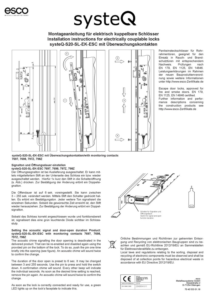
Signalton und Öff nungsdauer einstellen
systeQ-S20-SL-EK-ESC 7697, 7698, 797Z, 798Z
Der Öff nungssignalton ist bei Auslieferung ausgeschaltet. Er kann mittels mit-
geliefertem Stift an der Unterseite des Schloss ein bzw. wieder ausgeschaltet
werden. Hierfür 1x kurz den Stift in die Schalteröff nung (s. Abb.) drücken. Zur
Bestätigung der Änderung ertönt ein Doppelsignalton.
Die Off endauer ist auf 6 sek. voreingestellt. Sie kann zwischen
3 – 255 sek. verändert werden. Mittels Stift den Schalter gedrückt halten. Es
ertönt ein Bestätigungston. Jeder weitere Ton signalisiert die einzelnen Sekun-
den. Sobald die gewünschte Zeit erreicht ist, den Stift wieder herausziehen. Zur
Bestätigung der Änderung ertönt ein Doppelsignalton.
Sobald das Schloss korrekt angeschlossen wurde und funktionsbereit ist, si-
gnalisiert dies eine grün leuchtende Diode sichtbar im Schlossstulp.
Setting the acoustic signal and door-open duration Product: systeQ-S20-
SL-EK-ESC with monitoring contacts 7697, 7698, 797Z, 798Z
The acoustic chime signalling the door opening is deactivated in the delivered
product. That can be re-enabled and disabled again using the provided pin on
the bottom of the lock. To do so, push the pin one time briefl y into the opening
(see fi gure). An acoustic chime will sound twice to confi rm the change.
The duration of the door open is preset to 6 sec. It may be changed between 3
and 255 seconds. Use the pin to press and hold the switch down. A confi rmation
chime will sound. Every other beep will indicate the individual seconds. As soon
as the desired time setting is reached, remove the pin again. An acoustic chime
will sound twice to confi rm the change.
As soon as the lock is correctly connected and ready for use, a green LED lights
up on the lock’s faceplate to indicate this.
Schalter für Signalton und Öff nungsdauer.
Switch for signal and open function duration.
Montageanleitung für elektrisch kuppelbare Schlösser
Installation instructions for electrically couplable locks
systeQ-S20-SL-EK-ESC mit Überwachungskontakten
1
2
3
4
4
306 5 5
min. 316
systeQ-S20-SL-EK-ESC mit Überwachungskontakten/with monitoring contacts
7697, 7698, 797Z, 798Z
345
Hinweise / Note
Maximalmaße von Gang- und Standfl ügel:
3500 mm x 1600 mm h x b, max. 400 kg pro Flügel
Nachweis für Rauch- und Brandschutzeignung im jeweiligen Türsystem
und jeweilige Einbausituationen sind zu erbringen.
Maximum dimensions of moving leaf and fi xed leaf:
3500 mm x 1600 mm h x w, max. 400 kg per leaf
Evidence of smoke and fi re protection suitability in the
respective door system and respective installation situations must be
provided.
Schalter unter dem
Siegelaufkleber
Switch under the seal label
Achtung: Bei 12V Stellung und 24V Betrieb sind sofortige Defekte zu
erwarten.
Caution: In case of 12V setting and 24V operation immediate damage
is to be expected.
Der Schalter ist auf 24V voreingestellt und versiegelt. Nur für
12V Eingangsstrom ist der Siegel zu entfernen und der Schalter
auf 12V zu stellen.
The switch is preset to 24 V and sealed. Only for 12V input
current the seal is to be removed and the switch to be set to 12V.
Schalter für 12V oder 24V Eingangsstrom
Switch for 12V or 24V input current

400 mm
9650 L = Lo + 54 mm
SL
Art.Nr.
Stangenlängenberechnung
SL= Stangenlänge
Anschlussplan systeQ-S20-SL-EK-ESC mit Überwachungskontakten
Connection guide systeQ-S20-SL-EK-ESC with monitoring contacts
Zur Nutzung der digitalen Schnittstelle RS 485 wen-
den Sie sich bitte an esco.Ein Netzteil ist erforderlich.
Wir empfehlen das 21-387541 (12V DC, 2A), 21-
390232 (24V DC, 1,5A)
To use the digital interface RS 485, please contact
esco.A power supply is necessary. We recommend
the 21-387541 (12V DC, 2A),
21-390232 m(24V DC, 1,5A)
weiß
white
braun
brown
grün
green
gelb
yellow
grau
grey
rosa
pink
blau
blue
rot
red
schwarz
black
violett
purple
rosa, grau
pink, grey
rot, blau
red, blue
weiß, grün
white, green
braun, grün
brown, green
Öffnungstaster
Opening push-button
Nussüberwachung Panikseite
Follower monotoring on panic device side
Riegelüberwachung
Dead bolt monotoring
Überwachung Schließbart
Monotoring of locking cam
V
Warnhinweise
Der Netzanschluss darf nur von einer elektrotechnischen Fachkraft vorgenommen
werden. Beim Anschluss an 230V besteht Lebensgefahr. Das Netzteil muss eine
Stromquelle mit begrenzter Leistung gemäß EN 60950 sein. Der Ausgangsstrom darf
nicht mehr als 4 Ampere betragen.
Elektrische und elektronische Komponenten entsprechen den CE Normen
CE- Konformität gemäß 2014/30/EU
EN 61000-6-1 EMV Grundnorm Störfestigkeit
EN 61000-6-3 EMV Grundnorm Störaussendung
EN 60950 Gerätesicherheit
Technische Daten
Nennspannung: 12 - 24V
Max. Leistungsaufnahme: 12W
Stromaufnahme: 600mA max.
Standby: 100mA
Kontaktbelastbarkeit: 30V DC, 1A
Kabeldurchmesser: 6,5 mm
Kabeltyp: LIYY 14x0,14 mm²
Kabellänge: 10 m
Kupplungsfunktion: Arbeitsstrom, stromlos entkuppelt
Freigabezeit: 6s Voreinstellung, einstellbar
Summerfunktion: abschaltbar
Schnittstelle: RS 485, optional
Zugelassener Temperaturbereich: -25°C bis +70°C.
Eingänge: Öff nen, (Optokopplereingang gegen GND schalten)
Ausgänge: 3x Relaisausgänge mit Wechsler Kontakten.
Riegelüberwachung
(schaltet wenn der Riegel ausgeschlossen ist)
Überwachung Schließbart
(schaltet wenn der Schließbart gedreht wird)
Nussüberwachung Panikseite
(schaltet wenn der Drücker nicht betätigt ist)
Warnings
Only a qualifi ed electrician is permitted to connect it to the mains.
There is a danger of lethal injury when connecting to 230V.
The power supply must be a power source with limited output in accordance with EN
60950. The output current may not be more than 4 amperes.
Electrical and electronic components comply with CE standards
CE compliance according to 2014/30/EU
EN 61000-6-1 EMC - Generic standards; Interference immunity
EN 61000-6-3 EMC - Generic standards; Emitted interference
EN 60950 Equipment safety
Specifi cations
Rated voltage: 12 - 24V
Max. power consumption: 12W
Power consumption: 600 mA max.
Standby: 100mA
Contact rating: 30V DC, 1A
Cable diameter: 6.5 mm
Cable type: LIYY 14x0.14 mm²
Cable length: 10 m
Coupling function: Operating current,
decoupled in currentless state
Release time: 6 sec preset, adjustable
Buzzer function: deactivatable
Interface: RS 485, optional
Permissible temperature range: -25°C to +70°C
Inputs: Open, (Connect optical coupler input to GND)
Outputs: 3x relay outputs with change-over contacts.
Latch monitoring (switches when the latch is barred)
Monitoring of locking cam
(switches when the locking cam is turned)
Follower monitoring on panic device side
(switches when the handle is not actuated)
esco
Metallbausysteme GmbH
Dieselstraße 2
D-71254 Ditzingen
70 40 533 03.19
Örtliche Bestimmungen und Richtlinien zur getrennten Entsorgung und Recycling von elektro-
nischen Baugruppen sind zu beachten und gemäß EU-Richtlinie 2012/19/EU an Sammelstel-
len für Elektrosonderabfälle zu entsorgen.
Local laws and regulations relating to the sorting, disposal and recycling of electronic components
must be observed and shall be disposed of at collection points for hazardous electrical waste in
accordance with EU Directive 2012/19/EU.
esco
Metallbausysteme GmbH
Dieselstraße 2
D-71254 Ditzingen
Lo
This manual suits for next models
1
Table of contents
Other Esco Lock manuals
Popular Lock manuals by other brands

gebatronic
gebatronic TCS-Cody-T4 Instructions for assembly and use

Abus
Abus 2010 Fitting and operating instructions

Masterlock
Masterlock 3681 Programming instructions

Key Safe
Key Safe C500 Code change guide

Yale
Yale Assure Lock YRL216 Installation and programming instructions

Rittal
Rittal VX Assembly and operating instructions