3S TE100 User manual

TE100,200
I/P CONVERTER
INSTRUCTION MANUAL
3S Co., Ltd.
(E)IM-TE100/00-R6

Safety Preca tions
Always read these instr ctions before sing the I/P converter .
! WARNING:Indicates instr ctions that, if not followed correctly, “
may lead to death
or serio s inj ry”.
! Warnings
■Install the flame-proof version in compliance with the “New G idelines for Ind strial Electrical
Eq ipment Explosion-Proofing 1979” iss ed by the Ind strial Safety Instit te of the Ministry of
Labor and in accordance with “technical proced res that comply with international standards”.
■The flame-proof version and Intrinsically Safe version and Nonincendive may not be installed or
sed for hazardo s applications sing gases other than those applicable to the explosion-proofing
grade of the I/P converter.
■Perform adj stment (zero and span adj stment) of the flame-proof version in a non-hazardo s
environment or after making the environment non-hazardo s.
■Always t rn off the power before removing the terminal box cover or main cover.
■If intending to remove or disassemble the press re ga ge for maintenance or other p rposes,
always t rn off the s pply press re and wait for the press re in the pne matic circ it to drop to
zero before ndoing any screws or other fittings sed to attach parts.
■Always t rn off the s pply press re before replacing the pilot relay nit.
! CAUTION:Indicates instr ctions that, if not followed correctly, “
may ca se a fa lt
or other physical damage”.
! Ca tions
■Fit the I/P converter in the orientation shown in section 3.2
■As drain fl id or dirt in the s pply press re line may block the fixed orifice or ca se misoperation,
fit a 5[micro]m or finer air filter (s ch as an SSS Mini-Set filter) and se a dryer or similar to
ens re a clean air s pply.
■Using a l bricator on the s pply side may ca se a blockage in the fixed orifice or nozzle. Never se
a l bricator with this I/P converter.
0-0

- Table of Contents -
1.Usage --------------------------------------------------------------------------------------------- 1-1
1-1 Check the I/P Converter Specifications ------------------------------------------ 1-1
1-2 Transport ---------------------------------------------------------------------------------- 1-1
1-3 Storage Preca tions -------------------------------------------------------------------- 1-1
1-4 Install Location -------------------------------------------------------------------------- 1-1
2.Overview ----------------------------------------------------------------------------------------- 2-1
2-1 Feat res ------------------------------------------------------------------------------------ 2-1
2-2 Principle of Operation ----------------------------------------------------------------- 2-2
2-3 Specifications ----------------------------------------------------------------------------- 2-3
2-4 Model Codes ------------------------------------------------------------------------------ 2-3
2-5 Dimensions -------------------------------------------------------------------------------- 2-4
-6 Name of Parts ------------------------------------------------------------------------------ 2-5
3.Design and Installation ---------------------------------------------------------------------- 3-1
3-1 Design -------------------------------------------------------------------------------------- 3-1
3-1-1 Flame-Proof Version --------------------------------------------------------------- 3-1
3-2 Installation -------------------------------------------------------------------------------- 3-2
3-2-1 Pipe Mo nting ----------------------------------------------------------------------- 3-2
3-2-2 Wall Mo nting ----------------------------------------------------------------------- 3-2
3-3 Pne matic and Electrical Installation ------------------------------------------- 3-2
3-3-1 Pne matic Installation ------------------------------------------------------------ 3-2
3-3-2 Electrical Installation ------------------------------------------------------------- 3-3
(1)Flame-Proof Version ------------------------------------------------------------- 3-3,4
(2)Standard (Non-Explosion-proof) -------------------------------------------------- 3-5
4.Operation ----------------------------------------------------------------------------------------- 4-1
4-1 A to/Man al Switchover F nction ------------------------------------------------ 4-1
4-2 Zero and Span Adj stment ------------------------------------------------------ 4-2,3
4-3 Width of Range Adj stment --------------------------------------------------------- 4-3
5.Maintenance ------------------------------------------------------------------------------------ 5-1
5-1 Maintenance of Flame -Proof Models --------------------------------------------- 5-1
5-2 Periodic Inspection ---------------------------------------------------------------------- 5-1
5-3 Replacing the pilot Relay Unit ------------------------------------------------------ 5-2
5-4 Replacement Parts ---------------------------------------------------------------------- 5-2
6.Tro bleshooting -------------------------------------------------------------------------------- 6-1
0-1

1.Usage
1-1
Check the I/P converter Specifications
On receiving the I/P converter , check that the information on the nameplate on the front of the
I/P converter matches what yo ordered and confirm that the model code is correct.
1-2
Transport
To prevent damage d ring transport, leave the I/P converter in its packing ntil ready to install
and se.
1-3
Storage Preca tions
Store the I/P converter in a location that satisfies the following criteria.
●Not s bject to rain or moist re
●Not s bject to shock or other impact
●Normal room temperat re and h midity
1-4
Install Location
To maintain the working life and performance of the transd cer, observe the following
preca tions when sing the I/P converter.
(1) Ambient temperat re
If sing in a location s bject to heat radiation or large variations in temperat re, consider
fitting thermal ins lation.
(2) Atmosphere
Try to select a well-ventilated location and avoid corrosive atmospheres.
1-1

2.Overview
The TE100 and TE200 I/P converters convert an electrical signal (4 to 20mA DC) o tp t from a
controller or similar to a pne matic press re. The I/P converters feat re a compact design and
high acc racy, making them s itable for adj ster valve and similar instr mentation applications.
2-1
Feat res
◆Feat res
Ultra light-weight, compact design at 1.6 kg (1.8 kg with red cing valve fitted), the I/P
Converters are significantly lighter than previo s models. This makes them easy to se.
◆High acc racy
The I/P Converters se a high-acc racy sensor and the latest technology to achieve a high level of
conversion acc racy.
◆B ilt-in red cing valve
A model is available that incorporates a small dedicated red cing val e (Mini-Set XR100). This
eliminates the need for pne matic s pply piping.
◆Optim m mo nting
Both pipe mo nting and wall mo nting are available by well designed bracket.
These enable the I/P Converters to be sed in locations where space is limited.
◆100 and 200 series models are available
Both 100 series (with terminal box) and 200 series (no terminal box) models are available,
allowing yo to select a model that best s its
2-1

2-2
Principle of Operation
<Transd cer Operation Schematic>
As shown in the above schematic, the operation of the I/P Converter is controlled by applying a
4 to 20mA DC signal to the inp t which ca ses the internal circ it to generate a voltage. A drive
c rrent is also s pplied to the torq e motor which represents the circ it load to operate the
overall system. If the level of the inp t signal increases, the c rrent to the torq e motor [1]
increases and the flapper [2] moves so as to cover the nozzle [3] and raise the press re in the
pilot relay (pne matic valve) nozzle back-press re chamber [4]. The increased nozzle
back-press re ca ses a displacement in the diaphragm assembly [5] in the pilot relay, opening
the port’s [6] inlet valve seat [7]. This increases the o tp t air press re from the pilot relay. The
o tp t air press re is also applied to the press re sensor [8] and converted into an electrical
signal proportional to the press re. This electrical signal is then ret rned to the control circ it
where it is sed as a feedback signal. The control circ it compares the sensor signal against the
inp t signal to control the o tp t air press re to match the inp t signal.
2-2

2-3
Specifications
Series
Parameter TE100 (with terminal box)
TE200 (no terminal box)
S pply press re
140kPa
(
1.4kgf
/
cm
2
)
O tp t press re
20
~
100kPa
(
0.2
~
1kgf
/
cm
2
)
Inp t signal
4
~
20mADC
Acc racy
Acc racy
±
0.
5% Linearity
±
0.2% Hysteresis 0.2%
Repeatability 0.1%
O tp t air capacity
approx.
40Nl
/
min
Air cons mption
approx.
3Nl
/
min
(approx.
4Nl
/
min
with Mini
-
set fitted
)
Ambient
temperat re S
Standard ve
rsion (non
-
explosion
-
proof)
:
-
20
~
80
℃
Flame-proof : -20~60℃ ----
Air connection
Rc1
/
4
(
1/4
NPT
)
Electrical
G1
/
2
(
1/2
NPT
)
Ho sing
Non-explosion proof
Flame
-
proof
: Ex d IIB T6 (
T
C13351
)
―――
Weight
approx.
1.6kg
(1.8kg
with a Mini
-
set
)
i
ntegrated
)
approx.
1.3kg
(1.5kg
with a Mini
-
set
)
integrated
)
Material (Primary)
Al min m Die-casting
2-4 Model Codes
1
2
3
4
5
6
7
8
9
10
TE
□
□
□
-
□
□
/
□〇
□〇
□〇
□〇
1 2 3 4 5 6
Basic code Series Ho sing
Pne matic and
Electrical
Connections
Ambient Temperat re AM
F nction
TE
I/P
Converter 1 100 series
0
Standard
1
Rc1/4・G1/2
S
Standard version
(non-explosion-proof)
-20 ~
80℃ M
YES
2
*1
200 series
3
1/4NPT・G1/2 Flame proof -20 ~
60℃
5
Flame-
proof 5
1/4NPT・1/2NPT
7 8 9 10
Press re Units
Press re Ga ge Inp t Signal Mini-set
Pne matic Co pling
K2
200kPa G0
NONE M1 4~20mA R1 Rc1/4
M2
0.2MPa G1
OUT-side only M2 4~12mA N1 1/4NPT
P2
30psi G2
SUP-side
OUT-side
M3 12~20mA (NONE) Witho t Mini-set
B2
2bar M4
*2
Special
*1 : TE200 series is only non-explosion-proof.
*2 : Please contact s.
2-3

2-5
Dimensions
2-4
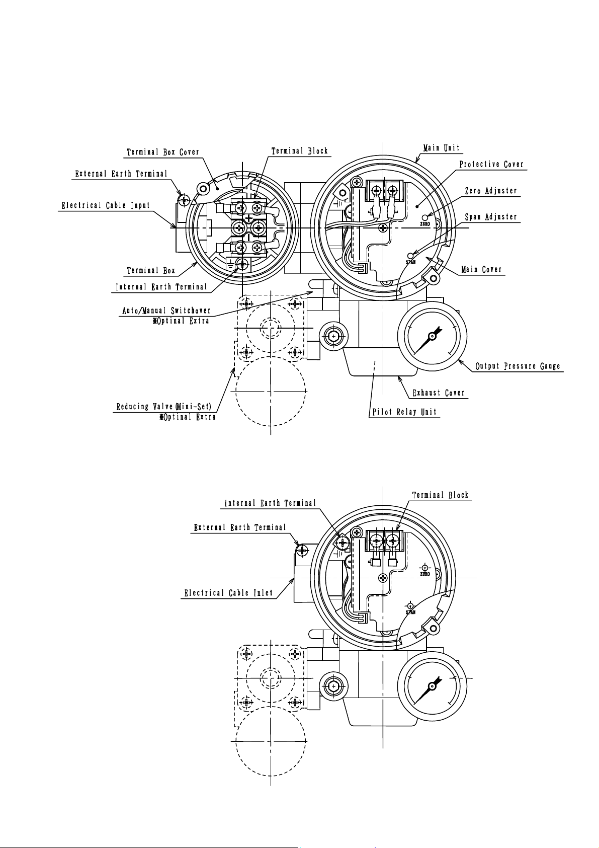
2-6 Name of Each Part
<TE100>
<TE200>
2-5

3.Design and Installation
3-1
Design
3-1-1 Flame proof
•
Do not se the I/P Converter in hazardo s environments containing gases other
than those applicable to the explosion-proofing grade of the transd cer.
•
Use the I/P Converter with the ambient temperat re in the range -20 to 60[deg]C.
3-1

3-2
Installation
3-2-1
Pipe Mo nting
3-2-2
Wall-Mo nting
3-3
Pne matic and Electrical Installation
3-3-1
Pne matic Installation
The I/P Converter req ires a clean and dry air s pply. Provide a system able to deliver s ch
an air s pply.
①
The I/P Converter can be ordered with either Rc1/4 or 1/4NPT co plings. Ens re yo se
the correct co plings to match those on I/P Converter.
②
Connect the piping sing the appropriate proced re depending pon whether a red cing
valve (Mini-Set XR100) is fitted or not.
If a red cing valve is not fitted, connect to the SUPPLY inlet on the I/P Converter.
If a red cing valve (Mini-Set XR100) is fitted, connect to the “P1” co pling on the Mini-Set
nit.
③
Ens re yo f lly p rge the piping before connection to prevent any particles of dirt or
foreign material from entering the system.
④
Adj st the s pply press re to deliver a 140kPa (1.4kgf/cm2) air s pply. If sing a Mini-Set,
t rn the adj stment knob on the Mini-Set to set the press re to 140kPa (1.4kgf/cm2).
3-2

3-3-2
Electrical Installation
(1)
Flame-proof version
When performing electrical installation, never remove the terminal box cover or
attempt to connect the wiring while the electrical power is still connected. (Similarly,
do not open the main cover.)
①
Cabling
Use ins lated cables able to withstand temperat res of 75[deg]C or higher for the
external cabling.
②
External cond ctor cabling
The following two methods can be sed for cond ctor cabling on the Flame-proof version
(Ex d IIB T6).
Cable pipe with threaded press re co pling method
Use a G1/2 thick steel cable pipe (PF1/2 eq ivalent) with a lock n t to provide a f ll
threaded co pling. Alternatively, se a sealing fitting.
Press re-proof packing method
Use a cable gland.
The table below lists the applicable cable diameters.
Cable glands with the part n mbers listed below are available as optional extras. Please
specify when ordering.
Model Standard Rating N mber
Applicable Cable
Diameters
Cable Gland Part No.
TE15●
Ex d IIB T6
TC13351
φ8~φ10
φ9~φ11
φ10~φ12
KHB-0-16/PK1610
KHB-0-16/PK1611
KHB-0-16/PK1612
*
Please contact s for NPT specification.
3-3
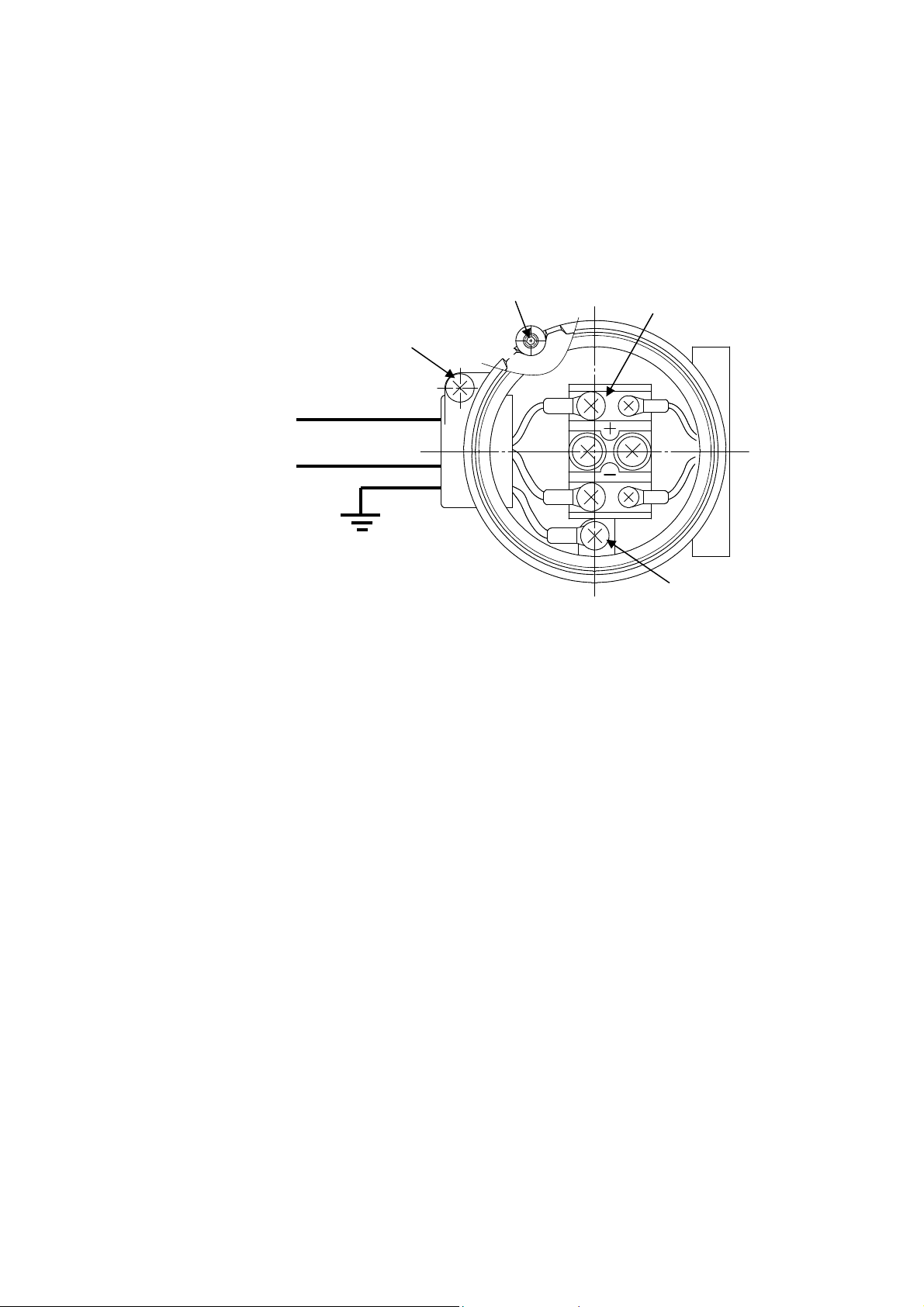
③
Connecting the cables
To connect the cables, remove the terminal box cover and se the ins lated crimping
terminals on the terminal block.
Connect by crimping the + inp t terminal to the + terminal (red) and the - inp t
terminal to the - terminal (bl e). (See Fig re 3-1)
* To remove the cover, ndo the locking screw (hex set screw)
.
Fig re 3-1
④
Locking
After partially attaching the terminal box cover, lock the cover in place sing the locking
screw.
⑤
Other details
All other aspects of the installation sho ld be carried o t in compliance with the “New
G idelines for Ind strial Electrical Eq ipment Explosion-Proofing 1979” iss ed by the
Ind strial Safety Instit te of the Ministry of Labor and in accordance with “technical
proced res that comply with international standards”.
3-4
+
-
Inp t Signal
Earth
2-M4 Screw
Internal Earth Terminal
External Earth Terminal
Locking Screw

(2)
Standard (non-explosion-proof)
①
Cabling
If the ambient temperat re is 60[deg]C or less, se 600V vinyl or better stranded cable.
If the temperat re is above 60[deg]C, select cable with an appropriate tolerance for the
conditions.
②
Connecting the cables
•
TE100 (with terminal box)
To connect the cables, remove the terminal box cover and se the ins lated crimping
terminals on the terminal block.
Connect by crimping the + inp t terminal to the + terminal (red) and the - inp t
terminal to the - terminal (bl e). (See Fig re 3-1)
•
TE200 (no terminal box)
Remove the main cover and connect to the terminal block on the circ it board as
described above.
The terminal polarities are indicated on the protective plate.
(See Fig re 3-2)
Fig re 3-2
3-5
4.Operation
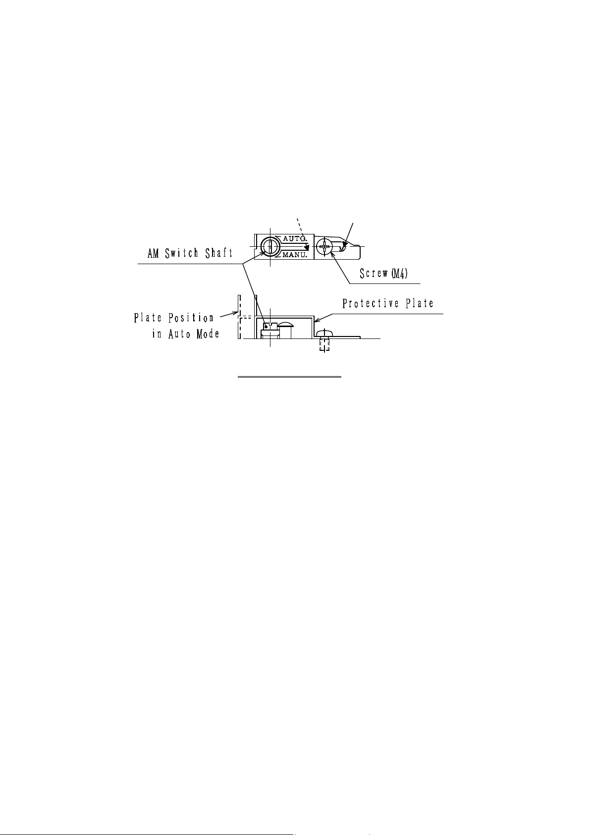
4-1
A to/Man al Switchover F nction
The I/P Converter is shipped set to a tomatic operation.
To operate the transd cer man ally, se the following proced re to switch to man al operation.
(See Fig re 4-1)
(The a to/man al switch is located on the left side of the I/P Converter nit.)
A to/Man al Switch
Fig re 4-1
<Changing to MANUAL>
[1] Undo the screw and slide the protective plate so that the “M” becomes visible. Partially
retighten the screw in this position.
[2] Next, se a screwdriver to rotate the AM switch shaft as far as it will go in the direction of
the arrow on the plate (MANU direction).
[3] Adj st the red cing valve sed to control the air s pply to set the I/P Converter o tp t
press re. The o tp t press re is indicated on the o tp t press re ga ge.
<Restoring to AUTO>
[1] To set back to AUTO, rotate the AM switch shaft as far as it will go in the AUTO direction.
[2] Slide the protective plate so that the “A” becomes visible again, then fasten in place.
4-1
M
A
4-2
Zero and Span Adj stment
(1) Set the AM switch f nction to AUTO and set the s pply press re to 140kPa (1.4kgf/cm2).
(2) Remove the main cover.
On the Flame-proof version, the main cover cannot be removed while the power
is on. Move to a non-hazardo s location before removing the main cover.
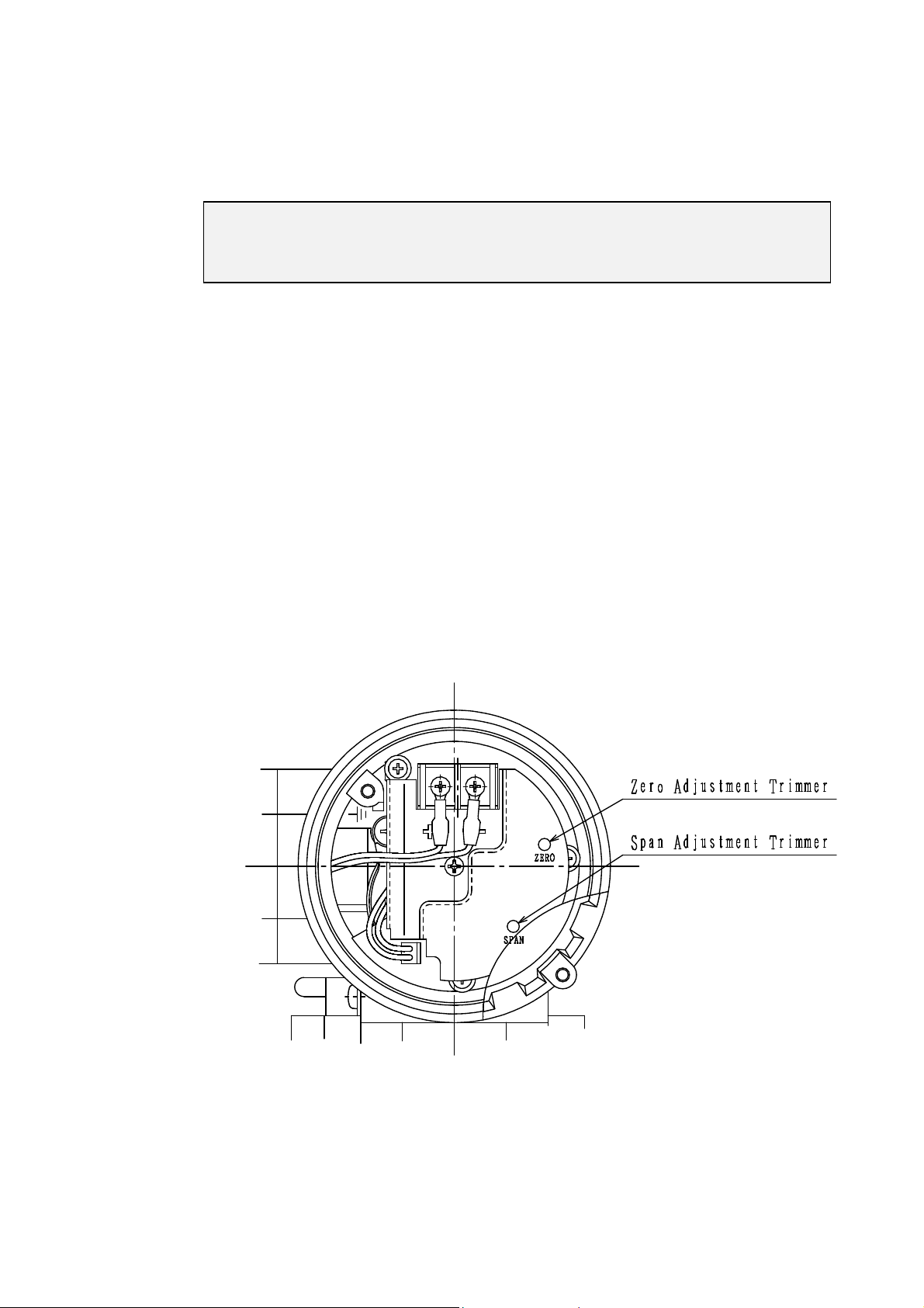
(3) Zero and span adj stment
(a) Apply a 0% (4mA) inp t signal
Rotate the zero trimmer to set the 0% o tp t (20kPa, 0.2kgf/cm2). Rotating clockwise
increases the o tp t and rotating co nter-clockwise red ces the o tp t.
(See Fig re 4-2)
(b)
Next, apply a 100% (20mA) inp t signal
Rotate the span adj stment trimmer to set the 100% o tp t (100kPa, 1.0kgf/cm2). Rotating
clockwise increases the span and rotating co nter-clockwise red ces the span.
(See Fig re 4-2)
(c)
Repeat the above adj stments two or three times to set the zero and span settings.
(d)
After yo have finished setting the zero and span adj stment, apply a step inp t (25%, for
example) and check that the o tp t is correct.
Fig re 4-2
4-2

(4)
1/2 split-range version
The I/O specifications for the 1/2 split range version are listed below.
Adj st the zero and span settings sing the same proced re as for the standard range
version.
Range 0% 100%
4~12mA
4mA 12mA
12~20mA
12mA 20mA
4-3
Width of Range Adj stment
The table below shows the width of the zero and span adj stment bands.
Yo can set the range to be different to the standard 0 to 100% o tp t provided yo stay
within these limits.
Zero adj stment width -10%~+10%
Span adj stment width +75%~+125%
4-3

5.Maintenance
5-1
Maintenance of Flame-Proof version.
1.When performing maintenance on Flame-proof version, never remove the terminal box
cover or main cover while the power is connected.
2.
Always t rn off the power before performing any maintenance or repair work.
5-2
Periodic Inspection
Performing periodic inspection and maintenance of the I/P Converter will help red ce the
incidence of fa lts and extend the working life of the nit.
<S pply press re filter>
・A metal mesh is fitted inside the SUPPLY co pling. Use a pair of tweezers or similar to
remove any sealing tape or dirt particles ca ght in the mesh.
<Fixed orifice assembly>
・The fixed orifice plays an important role in s pplying the air to the nozzle. If no nozzle back
press re is present, this may indicate a blocked orifice.
・Take off the exha st cover, then remove the fixed orifice assembly from the pilot relay nit
and replace with a spare assembly. (See Fig re 5-1)
・If yo do not have a spare fixed orifice assembly, se [phi]0.3 piano wire or similar to clean
the blocked orifice. Then se clean air to blow off any remaining dirt.
・When finished cleaning, screw the assembly back into its original position. Take care to
ens re that the O-ring is positioned correctly in the body of the pilot relay nit.
Fig re 5-1
5-1
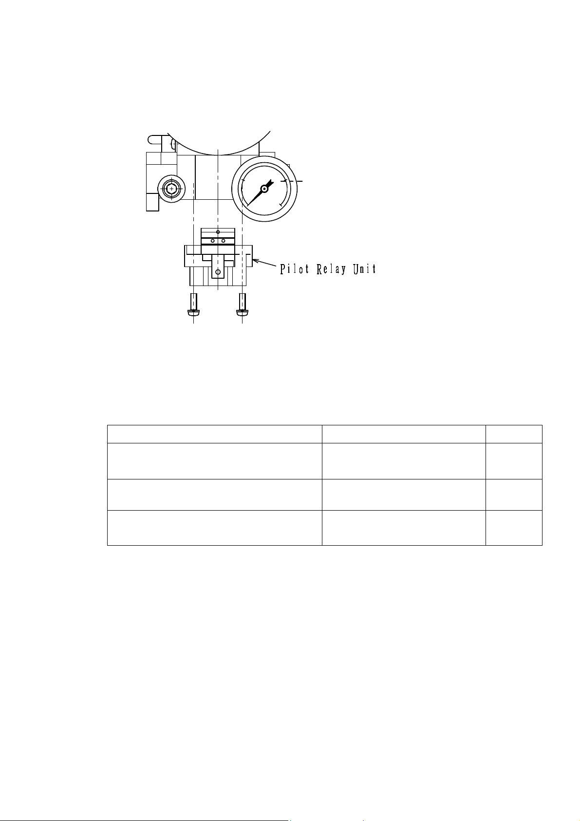
5-3
Replacing the Pilot Relay
To remove the pilot relay nit, remove the exha st cover from the bottom of the I/P Converter
and ndo the two screws. (See Fig re 5-2)
Fig re 5-2
5-4
Replacement Parts
Name
Part No.
Q antity
Circ it board
TE100:
TE100-500-11A 1
TE200:
TE100-500-11B
Pilot relay nit
TE100-200 1
Filter for red cing valve
XR100-109 1
5-2

6. Tro bleshooting
Refer to the table below in the event of problems with the I/P Converter .
If the action described below does not restore the transd cer to normal operation, replace the I/P
Converter with a spare and contact s.
Symptom Ca se Action
I/P Converter
does not operate
when an inp t
signal is applied.
Fixed orifice is blocked. Clean or replace fixed
orifice.
I/P Converter
is set to man al
operation.
Change to A to (A)
operation.
Polarity of inp t signal wiring is
reversed.
Check wiring and
connections.
No air s pply S pply 140kPa
(1.4kgf/cm[2])
Pilot relay is fa lty. Inspect and/or replace
pilot relay.
O tp t is
nstable.
Large fl ct ation in air s pply
press re
Ens re air s pply
press re is constant.
The press re leakage (vol me) on
the o tp t circ it side is fl ct ating.
Check for press re leaks.
Pilot relay is fa lty. Inspect and/or replace
pilot relay.
Large o tp t
error
Zero and span settings are o t of
adj stment.
Re-adj st zero and span
settings.
Large fl ct ation in ambient
temperat re
Fit thermal ins lation or
similar.
Press re leak in o tp t circ it Fix press re leak.
6-1
This manual suits for next models
1
Table of contents
Popular Media Converter manuals by other brands


Softing
Softing Echochange manual

Omnitron Systems Technology
Omnitron Systems Technology OmniRepeater AS400/3X Specifications

Pathos Acoustics
Pathos Acoustics Converto user manual

WoMaster
WoMaster DS201 Quick installation guide

DYNAPAR
DYNAPAR SERIES HS35R installation manual

Science Image
Science Image NDI Studio 4K SH quick start


