1
Chapter1 BeforeUsingtheProduct
1-1.Overview
This unit is an interface converter that converts PC’s USB port to an RS-232C, RS-422, or RS-485 port. A
photo coupler and an isolation transformer electrically isolate the USB port from the conversion port,
which is ideal for FA equipment and medical equipment that require high safety and reliability. It is able to
access the USB port as a COM port using the application software by virtual COM port driver.
1-2.Specification
*1: Single wire: 0.2-2.5 mm2. Stranded wire: 0.2-1.5 mm2, AWG24 to 14. Refer to [3-4 Cable Connection]
for more details.
*2: Speed is established in application software. Certain speed beyond 1.2Mbps cannot be established.
(SI-35USB/SI-20USB)
*3: SI-35USB can control the transmission timing by using the line monitor function (refer to [3-1])
*4: Supports 32bit/64bit Windows 8/7. Cannot help any problems occurred on Windows ME/98SE/98.
S
ecifications
SI-35USB SI-20USB SI-55USB
Conversion USB⇔RS-422/485 USB⇔RS-422 USB⇔RS-232C
USB Interface RS-422/485
5 pole terminal block (5.08mm
press-to-screw pitch type*1) Rated
torque/ Screw size: 0.25Nm/M3
RS-422
DSUB 9pin (male)
Screw #4-40UNC
RS-232C
DSUB 9pin (male)
Screw #4-40UNC
Built-in terminater ON/OFF.
Line monitor, Auto driver control.
Built-in Terminater
SD, RD, RTS, CTS
conversion
DTE
(Equivalent to PC com port)
Asynch Type
Baud Rate 300 to 1Mbps *2
Data Frame
Flow Control
Surge Protection
Isolation Protection
System
Requirements
LED
Power USB Bus power, DC5V±10%,
Max. 250mA USB Bus power,
DC5V±10%, Max. 230mA USB Bus power, DC5V±10%,
Max. 270mA
Temperature
Humidity
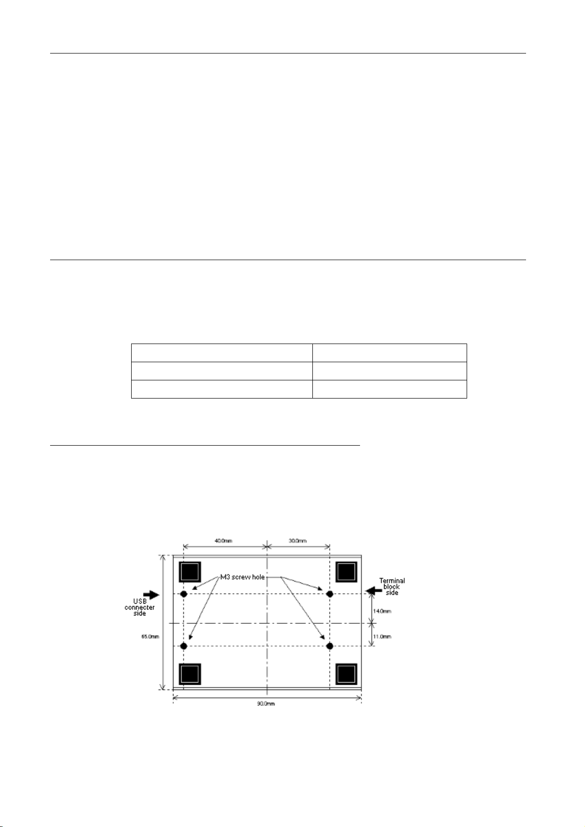
Dimension
& Weight 65(W)×90(D)×22(H)mm
Approx. 200g
Mounting Method
Composition
PC: PC/AT compatible with USB port (DOS/V PC)
OS: Microsoft Windows 8/7/Vista/XP/ME/87SE/98 *4
USB1.1/2.0, full speed transmission B connector
Data bits[7or8] + Parity[Even/Odd/none] + Stop bits[1/2]
300 to 3Mbps*2
Asynch
Using M3 screw hole in the bottom face, installation to a DIN rail (SI-DIN70 is required.)
USB cable (1.8m), Utility CD, Instruction manual, Warranty.
Serial Interface
Transmission: TXD, Reception: RXD, Power: PWR
In operation: -10 to 55°C, In storage: -20 to 75°C
In operation: 10 to 90%RH, In storage: 10 to 90%RH (No condensation)
65(W)×95(D)×22(H)mm
Approx. 200g
Xon/off, RTS/CTS*3 (supported by COM port emulator)
15KV ESD
3000Vdc