www.womaster.eu
・Support
At WoMaster, you can use the online service forms to request the
support. The submitted forms are stored in server for WoMaster
team member to assign tasks and monitor the status of your service.
Please feel free to write to help@womaster.eu if you encounter any
problems.
WoMaster reserves the right to make changes to this QIG or to the
product hardware at any time without notice. It is the user’s
responsibility to determine whether there have been any such
updates or amendments herein.
Defects, malfunctions, or failures of the warranted Product(s) caused
by damage resulting from unforeseeable incidents (such as lightings,
floods, fire, etc.), environmental and atmospheric disturbances, other
external forces such as power line disturbances and surge, host
computer malfunction and virus, incorrect power input, or incorrect
cabling, incorrect grounding and damages caused by misuse, abuse
and unauthorized alteration or repair are not warranted.
・Disclaimer
・Warranty
5-year Global warranties are available for WoMaster products
assuring our customers that the products shall remain free from
defects in workmanship or materials and conform in all material
respects to WoMaster specifications, or Purchaser’s supplied and
accepted specifications. The warranty is limited to the repair and/or
replacement, at WoMaster‘s sole discretion, of the defective product
during its warranty period. The customer must obtain a Return
Merchandise Authorization (RMA) approval code prior to returning
the defective Product to WoMaster for service. The customer agrees
to prepay shipping charges, to use the original shipping container or
equivalent, and to insure the Product or assume the risk of loss or
damage in transit. Repaired or replaced products are warranted for
ninety (90) days from the date of repair or replacement, or for the
remainder of the original product's warranty period, whichever is
longer.
V1.1 Dec 22, 2021 3160-0DS2010-01 © WoMaster Inc. All rights reserved.
LED Status Description
Power Green on Power On
Off Not Receiving Power
LFP Green On Link Loss Forward / Link Fault
Pass Through function is Enabled
Green Blinking Link Loss Event Occurred
Off LLF is disable
100FX
LNK/ACT
(SFP)
Green On SFP Fiber Speed setting on
100Mbps and Link Up
Green Blinking SFP Transceiver is on forwarding.
Off No Link
1000FX
LNK/ACT
(SFP)
Yellow On SFP Fiber Speed setting on
1000Mbps and Link Up
Yellow Blinking SFP Transceiver is on forwarding.
Off No Link
RJ-45
Yellow On Link Speed 1000Mbps
Green On 10/100/1000Mbps Link
Green On &
Yellow Off Link Speed 10/100Mbps
Green Blinking RJ-45 is on forwarding
Off No Link
SC Fiber Port Yellow On 1000Mbps Fiber Link
Yellow Blinking 1000Mbps Activity
・LED Indicators
DS201/DS201F deliver smart auto forwarding mode change function. If
the RJ-45 link speed and duplex mode is not same as fiber port, then it
will auto change to Store and Forwarding mode with higher forwarding
latency.
With the same speed and duplex mode, the DS201/DS201F will active
in pure-converter mode with extreme low latency - 8.2x10⁻⁹ Sec.
To obtain best network performance, please ensure both of RJ-45 and
Fiber are linked in same speed and duplex mode.
・Auto Forwarding Mode Change
Link Loss Forwarding (LLF) or Link Fault Pass-Through (LFPT) function
is supported in DS201/DS201F when LFP LED blinking, please check
the cable connection. The event may cause by RJ-45 link-down of local
or far-end site, fault fiber connection. It is recommended to enable the
LLF function of both local and far-end site to obtain a quick alarm.
(The LLF/ Link Fault Pass Through function supports bi-directional
forwarding and with auto recovery.)
・Link Loss Forwarding / Link Fault Pass Through
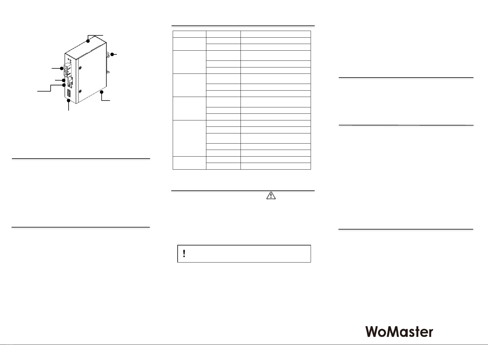
System LED
• 1x Power
• 1x LFP
• 1x Fiber Status
SC (1000M)
RJ-45 (100M/1000M)
DIP Switch
• LFP (Off, On)
• RJ-45 (Auto/Off, 100H/On)
Power Input
• 4-Pin Removable Terminal Connector
• Dual Power Input
• DC 10~60V, or AC 18~30V
Chassis
Grounding Screw
DIN Rail Clip
Steel Metal, IP31
DS201F:
Grounding: The well grounding is important for EMC protection
and make sure everything is done correctly before power on the
system. To avoid system damage, the equipment should be
connected to Earth Ground.
NOT allow to open the housing: Only technicians authorized
by the manufacturer are permitted to open the housing.
Please always read the latest version User Manual to know the
product specification, installation ste.ps and notice.
Power Specification: Follow the power installing instruction of the
user manual, it indicates the available input voltage range, V+/V- pin
assignment, power consumption and other notice.
Switch ON Notice: Only switch on the supply voltage while the
housing is closed, the input voltage is correct and the terminal blocks
are wired correctly.
Wiring: The connection cables used are permitted for the specified
electronic voltage, current, wire diameter and temperature range. The
quality of the RJ45 connector is also very important. In harsh
environment, inferior quality RJ45 plug may also cause damage, short
or fault communication.
Statement regarding restricted access: The equipment is
intended to be used in a restricted access location. Access should
only be given to skilled person or instructed person who has been
instructed in the operation of the equipment.
Only operate the device at the specified ambient temperature
and humidity.
・Safety Precautions
Connecting power with reverse polarity or using the wrong type of power
supply may damage the equipment. Make sure that the power supply is
connected correctly and of the recommended type.