4EVAC 4E-FMWB User manual

Hacousto Holland bv
Industrieweg 87
2651BC Berkel & Rodenrijs
4E-FMWB installation and user guide
Author:
DD
Page 1of 17
SUMMARY
This document includes both the installation and user guides of the 4E-FMWB, the wall-box fireman’s
microphone dedicated to 4EVAC Voice Evacuation Systems. It explains how the 4E-FMWB should be
installed and configured. The installation instructions are addressed to trained technical personnel, such as
installers, service technicians and commissioning engineers. User instructions explain how to operate the
4E-FMWB and how to interpret indications by the end users as well as technical personnel, such as service
technicians.
REVISION AND APPROVAL
Rev.
Date
Nature of Changes
Approved By
01
30-07-2019
Original draft
DD
02
11-06-2020
Corrections
TvdH

Hacousto Holland bv
Industrieweg 87
2651BC Berkel & Rodenrijs
4E-FMWB installation and user guide
Author:
DD
Page 2of 17
Table of Contents
1. What is the 4E-FMWB?.......................................................................................................................................................... 3
2. Where do I start?..................................................................................................................................................................... 3
3. Configuration settings ........................................................................................................................................................... 5
4. Hardware installation and settings.................................................................................................................................... 6
Housing installation ...................................................................................................................................................... 6
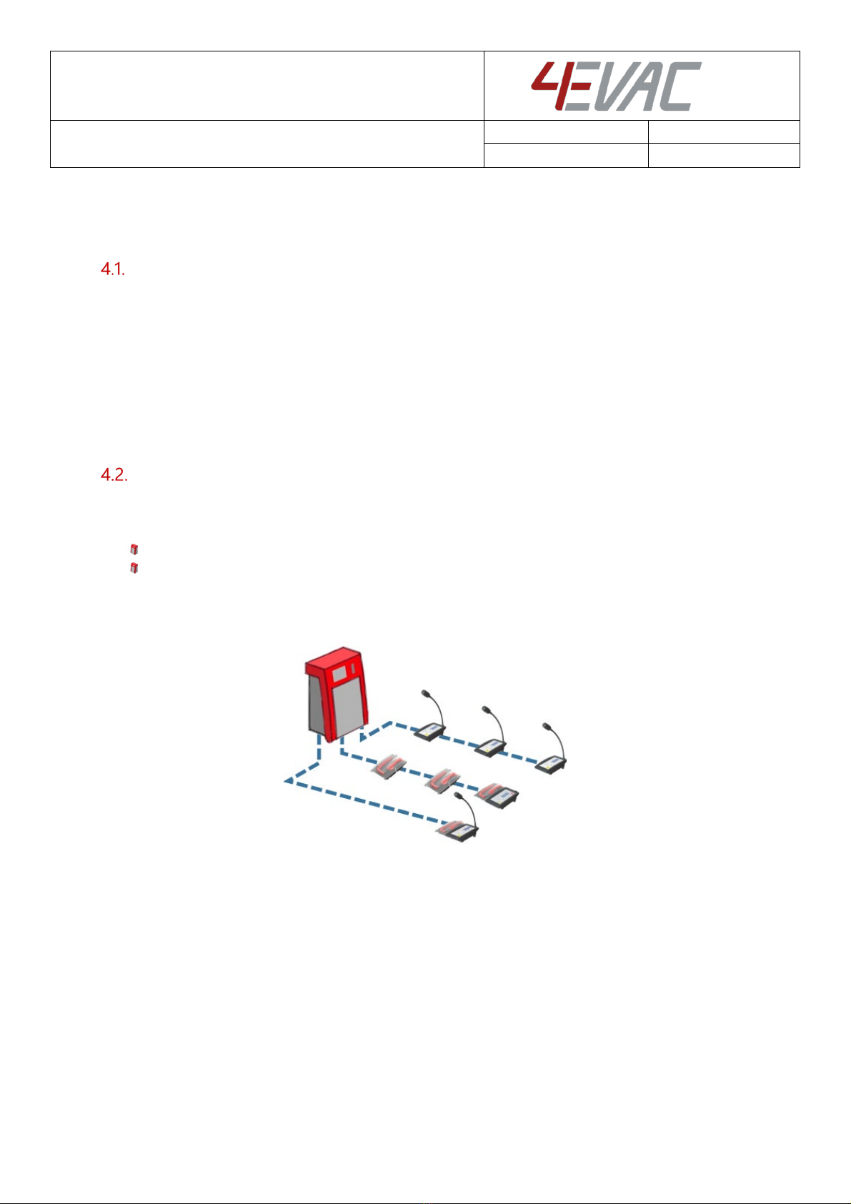
L-Net .................................................................................................................................................................................. 6
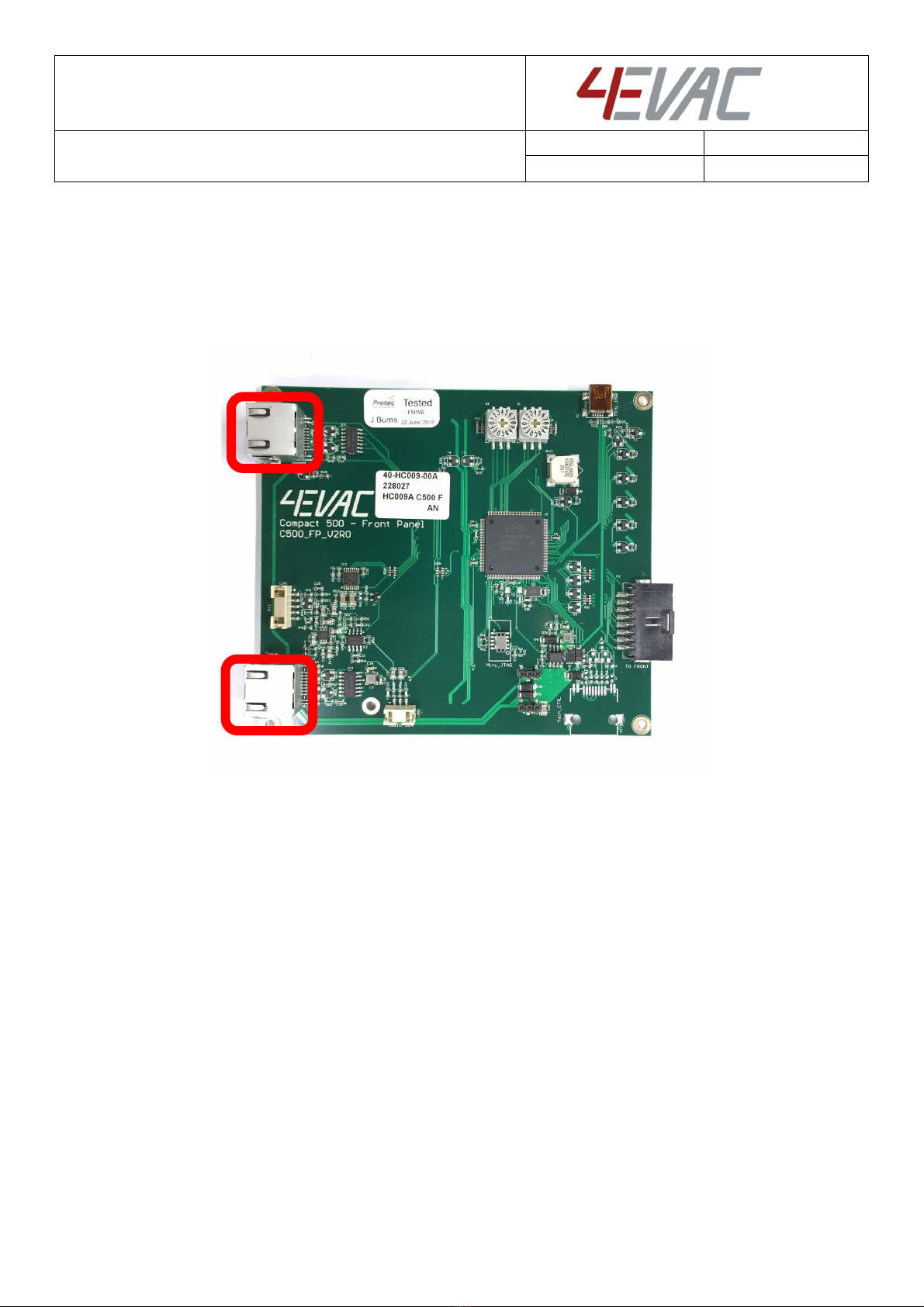
4.2.1. Network ports....................................................................................................................................................7
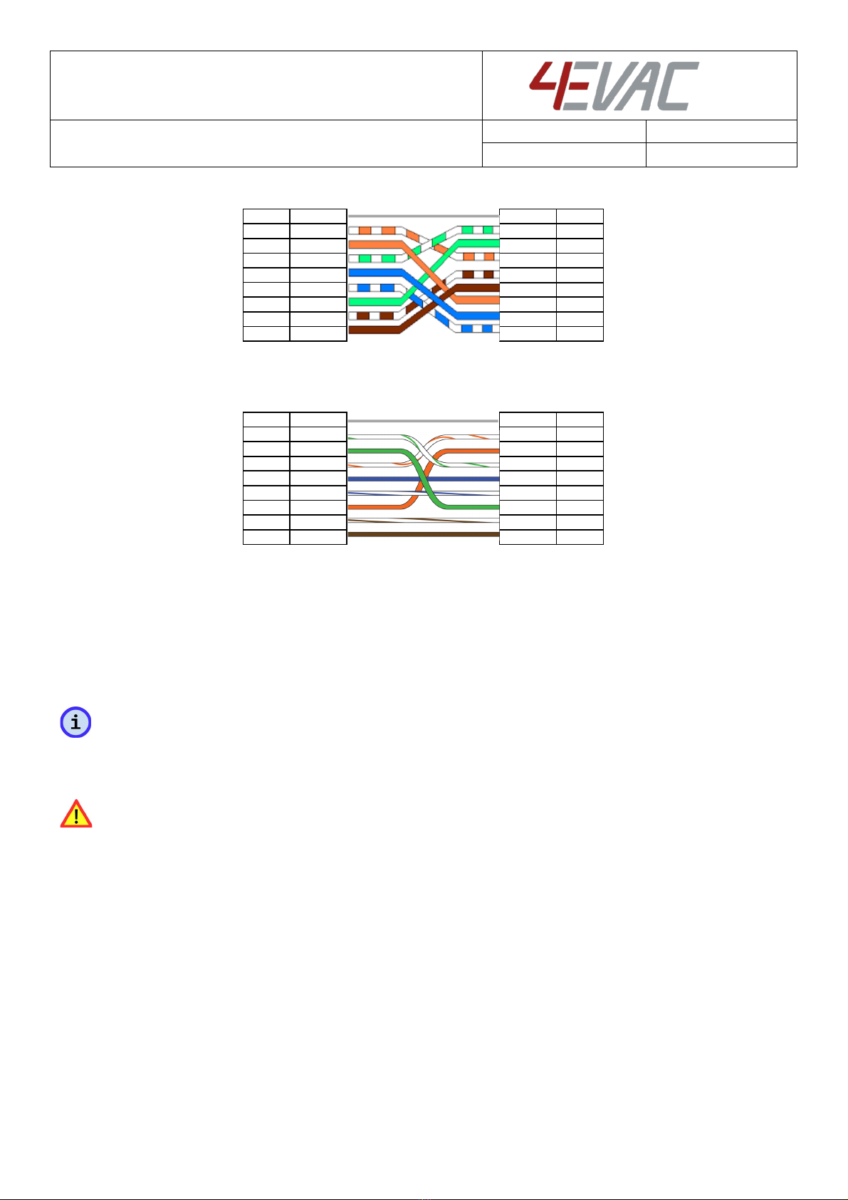
4.2.2.Network cabling................................................................................................................................................7
Device ID........................................................................................................................................................................... 9
5. Front Panel................................................................................................................................................................................10
LED indicators ................................................................................................................................................................10
5.1.1. POWER...............................................................................................................................................................10
5.1.2. EVAC ...................................................................................................................................................................10
5.1.3. FAULT ................................................................................................................................................................. 11
5.1.4. POWER SUPPLY .............................................................................................................................................. 11
5.1.5. SYSTEM FAULT ................................................................................................................................................ 11
5.1.6. NETWORK ......................................................................................................................................................... 11
5.1.7. Zone indicators ...............................................................................................................................................12
Manual controls ............................................................................................................................................................14
5.2.1. SILENCE..............................................................................................................................................................14
5.2.2.LAMP TEST........................................................................................................................................................14
5.2.3.ZONE selection................................................................................................................................................14
5.2.4.RESET..................................................................................................................................................................14
5.2.5.FUNCTION button..........................................................................................................................................14
6. Integrated fireman mic.........................................................................................................................................................15
7. Technical specifications........................................................................................................................................................16

Hacousto Holland bv
Industrieweg 87
2651BC Berkel & Rodenrijs
4E-FMWB installation and user guide
Author:
DD
Page 3of 17
Thank you for choosing 4EVAC as your Voice Evacuation System solution.
The 4EVAC Compact 500 is an all-in-one Voice Evacuation System box. The box contains a completely
integrated Voice Evacuation System, capable of both standalone and network operation. The 4EVAC
Compact 500 is certified in accordance with EN54-16 and EN54-4, which are harmonized standards under
the Construction Products Regulation, mandatory in the European Union.
1. What is the 4E-FMWB?
The 4E-FMWB is a wall mounted microphone paging station
with pushbutton panel and fireman microphone. It can
address up to 6 zones for emergency EVAC paging. 4E-FMWB
includes a fist microphone with a built-in PTT button, which
can be pre-programmed to access certain zones or group of
zones. The EVAC and ALERT messages may be triggered on
the front panel of the 4E-FMWB by means of dedicated
buttons.
Additionally, the 4E-FMWB incorporates mandatory EN-54-16
system indications, as well as a fault/emergency buzzer and
mandatory manual controls, including a Lamp Test and system reset.
The 4E-FMWB is connected to the L-Net interface of the 4EVAC system main unit (Compact 500 or Impact
Controller) and may be daisy-chained with more L-Net devices. The 4E-FMWB is dedicated to EVAC / ALERT
messages and live EVAC paging and is not suitable as a commercial or general purpose paging microphone.
The 4E-FMWB operates with full fault monitoring of the microphone, where the microphone transducer,
PTT button and cable are surveilled.
2. Where do I start?
First, make sure that you are officially allowed to access the hardware of 4EVAC system devices. This is
usually the case if:
you are an authorized representative of 4EVAC;
you have been trained by 4EVAC or one of its authorized representatives for installation, service
and commissioning of 4EVAC Voice Evacuation Systems.
Unauthorized hardware and/or software modifications are against the law and outside of the
manufacturer’s responsibility. If you have doubts about your status and access level permissions, please
contact the 4EVAC main office.
Important note: Access level 3 explanation

Hacousto Holland bv
Industrieweg 87
2651BC Berkel & Rodenrijs
4E-FMWB installation and user guide
Author:
DD
Page 4of 17
Opening the device housing or tampering with network cabling is
restricted. This gives access to all interfaces, internal system
connections and sensitive hardware settings that are of high
importance to system operation mode, hardware reliability and safety
(Access Level 3 according to EN54-16, Annex A). This access level (and
higher) is strictly protected by the manufacturer and reserved only for
service personnel which is trained, approved and officially certified by
the manufacturer. Any actions carried out in Access Level 3 without the
manufacturer’s explicit approval may lead to incorrect settings or
hardware damage, causing serious system malfunction, and therefore
are strictly prohibited and void manufacturer’s warranty.

Hacousto Holland bv
Industrieweg 87
2651BC Berkel & Rodenrijs
4E-FMWB installation and user guide
Author:
DD
Page 5of 17
3. Configuration settings
The settings for the 4E-FMWB are included in the configuration file located on the micro SD memory card
installed in the 4EVAC system main unit (Compact 500 or Impact controller).
The configuration file includes user-defined settings, such as:
1. zone selection buttons,
2. microphone volume level,
The configuration file should be prepared in the 4EVAC Manager. The 4EVAC Manager is GUI software
running on Windows OS. More information about 4EVAC Manager can be found in the software manual
“4EVAC Manager User Manual”.
NOTE: Please make sure that the configuration file is prepared with the version of 4EVAC Manager
compatible with the system’s firmware.
The installation file of the latest 4EVAC Manager and the manual are available on our website:
www.4EVAC.com

Hacousto Holland bv
Industrieweg 87
2651BC Berkel & Rodenrijs
4E-FMWB installation and user guide
Author:
DD
Page 6of 17
4. Hardware installation and settings
Housing installation
4E-FMWB is dedicated to wall mounting by means of four wall plugs or screws, directly to the wall structure.
Before fixing the housing:
1. Make sure that there is enough room to open the front door after the housing is fixed;
2. Make an opening for the network cable in any wall of the 4E-FMWB (except the front door) and
secure it with a cable gland.
Mount the housing at an average line of sight, with its center approximately 160cm above floor.
L-Net
4E-FMWB is a remote station connected to an L-Net port of 4EVAC main unit. Multiple 4E-FMWB stations
may be used in the same L-Net, with the following limitations:
A maximum of 8 stations per L-Net port
A maximum of 16 stations per single 4EVAC main unit (total sum of all 3 L-net ports)
The microphone station may be also daisy-chained together with other L-Net devices
Compact 500 L-Net (local network)

Hacousto Holland bv
Industrieweg 87
2651BC Berkel & Rodenrijs
4E-FMWB installation and user guide
Author:
DD
Page 7of 17
4.2.1. Network ports
4E-FMWB offers 2 L-Net ports (RJ-45) for network connections to the 4EVAC main unit and distributed
parts of the 4EVAC Voice Evacuation System. Both L-Net ports are equal, therefore there is no difference
which port is connected to which side of L-Net daisy-chain.
Internal view of 4E-FMWB – L-Net ports
4.2.2.Network cabling
The 4EVAC network features a full duplex RS-422 data link and 24V DC power to remote devices.
If you’re building a distributed system using the 4EVAC network, you should make physical links between
devices using the right cables. The cabling should meet the following requirements:
1. A crossover twisted-pair cable (compatible with Ethernet crossover)

Hacousto Holland bv
Industrieweg 87
2651BC Berkel & Rodenrijs
4E-FMWB installation and user guide
Author:
DD
Page 8of 17
2. CAT5e or higher for maximum distance of 250m.
3. Non-CAT / lower than CAT5e: 250m not guaranteed.
4. Shield required (at least FTP)
NOTE: If you use a straight cable, the device will power up but the Tx/Rx data terminals will not be properly
connected. This will result in a communication fault between the L-Net device and the 4EVAC main unit.
The L-Net device will not be able to initialize, thus will remain in boot-sequence, not operational.
Caution! Use only crossover cables and keep the correct pinout! Connecting power pins to data pins will
damage the network port.
pin number pin number
GND shield shield GND
RX+ 1 1 RX+
RX- 2 2 RX-
TX+ 3 3 TX+
power + 4 4 power +
power - 5 5 power -
TX- 6 6 TX-
power + 7 7 power +
power - 8 8 power -
pin number pin number
GND shield shield GND
RX+ 1 1 RX+
RX- 2 2 RX-
TX+ 3 3 TX+
power + 4 4 power +
power - 5 5 power -
TX- 6 6 TX-
power + 7 7 power +
power - 8 8 power -
xover type A cable
xover type B cable

Hacousto Holland bv
Industrieweg 87
2651BC Berkel & Rodenrijs
4E-FMWB installation and user guide
Author:
DD
Page 9of 17
Device ID
The microphone station needs an ID setting in order to be properly recognized in the network and operate.
If the device ID is duplicated or set to a wrong value, the device will not receive the correct configuration
settings from the 4EVAC main unit. In this case the remote station will be stuck in its boot sequence and
remain non-operational.
The device ID is set by means of two rotary switches, which define the two-digit hexadecimal value of the
ID.
In order to check or set the Device ID, you must access the rotary switches on the back side of the unit:
1. Open the housing
2. Unmount the front plate from the mounting studs
3. Pull the front plate out and turn around to get access to the internal PCB.
4. Identify the high-significant and low-significant rotary switches. The Device ID is a combination [HI
LO] of those two digits.
5. Make sure the ID value exists in your configuration settings, relates to the right device type and is
not duplicated on another device. Allowed values: 01-FE
6. Set the Device ID value according to the configuration settings of the 4EVAC system.
7. Plug in the L-Net cable connecting the station with the 4EVAC main unit.
8. Observe the boot sequence, after which the system should automatically enter normal operating
mode.
9. Put the front plate back in its place and assemble.
10. Close the housing.
4E-FMWB internal view: Device ID setting

Hacousto Holland bv
Industrieweg 87
2651BC Berkel & Rodenrijs
4E-FMWB installation and user guide
Author:
DD
Page 10 of 17
5. Front Panel
Compact 500 front panel
LED indicators
5.1.1. POWER
Indicates the operating status of the 4E-FMWB.
Continuous: the device is powered and ready
Blinking fast: the device is booting, not ready for full operation
5.1.2. EVAC
Indicates that the system is in its Voice Alarm state, where at least one zone in the system is occupied by
an emergency audio signal, i.e. a pre-recorded EVAC MESSAGE or LIVE EVAC, when a fireman mic is being
used.
Continuous: EVAC state

Hacousto Holland bv
Industrieweg 87
2651BC Berkel & Rodenrijs
4E-FMWB installation and user guide
Author:
DD
Page 11 of 17
5.1.3. FAULT
Indicates that the system is in a FAULT condition (general fault indicator), where at least one device in the
system is reporting a fault.
Continuous: when a local fault is detected
Blinking slow: when a local device is healthy and at least one remote device is reporting a fault
state
5.1.4. POWER SUPPLY
Indicates a power supply fault of the local 4EVAC main unit, where at least one of following faults is
reported:
Continuous: mains fault
Blinking slow: battery-related fault:
oLoss of battery
oLoss of charger
oBattery resistance too high
oTemperature fault
oCharger communication fault
5.1.5. SYSTEM FAULT
Indicates a system fault, where:
- A CPU or program execution is stopped or malfunctioning.
- Storage memory containing config settings and audio files (SD card) is corrupted.
- The front panel is not communicating with main board.
Where the system fault is caused by a CPU or memory fault, the system remains in a “safe state”, where
critical functions (including audio transmission, reaction on control inputs, etc.) are stopped until the fault
is removed.
Continuous:
oCPU / program fault
ofront panel fault
Blinking slow:
oSD card fault
oConfig file not compatible
oWrong ID setting
5.1.6. NETWORK
Indicates when any device or link in the network is missing.
Blinking slow:

Hacousto Holland bv
Industrieweg 87
2651BC Berkel & Rodenrijs
4E-FMWB installation and user guide
Author:
DD
Page 12 of 17
Global ring is broken (any place in the ring)
Continuous:
At least one device from the network is missing.
5.1.7. Zone indicators
Zone indicators are strictly related to the corresponding zone button. If a button is not attached to any
zone, then the zone indicators for this button are disabled.
Manual zone control
5.1.7.1. Red
Indicates that the zone is in EVAC condition, where the zone is occupied by one of the following audio
signals:
Continuous: LIVE EVAC
Blinking slow: EVAC Message.
5.1.7.2. Yellow
Indicates that the zone is transmitting an ALERT message, and/or is in fault state
Continuous: Zone fault (fault of any line / amplifier included in this zone)
Blinking slow: Zone is transmitting an ALERT Message.
5.1.7.3. Blue
Zone busy / zone selection LED.
Continuous: indicates that the zone is manually selected via
the zone selection button on the local panel
Blinking fast: the zone is occupied by an audio signal, but is
in SILENCE mode (triggered by SILENCE input or manual
SILENCE button)
Blinking slow: indicates that the zone is currently transmitting
an audio signal (except BGM) from another device.
Blinking double: indicates that the zone is currently
transmitting an audio signal from this microphone station.
NOTE: BGM transmission is not indicated.
OFF
Blink slow
Blink double
Blink fast
continuous
LED indication time chart
Zone A

Hacousto Holland bv
Industrieweg 87
2651BC Berkel & Rodenrijs
4E-FMWB installation and user guide
Author:
DD
Page 13 of 17
Zone indicators are strictly related to the corresponding zone button. If a button is not attached to any
zone, then zone indicators for this button are disabled.

Hacousto Holland bv
Industrieweg 87
2651BC Berkel & Rodenrijs
4E-FMWB installation and user guide
Author:
DD
Page 14 of 17
Manual controls
5.2.1. SILENCE
Press to mute the sound of the buzzer in the entire system.
5.2.2.LAMP TEST
Press to verify visual (LEDs) and audible indications (buzzer) of the local front panel.
5.2.3.ZONE selection
Press to select a zone. Press again to deselect.
NOTE: Zone selection will clear automatically after the timeout triggers, which is defined in the configuration
settings.
5.2.4.RESET
Press to clear your current zone selection.
5.2.5.FUNCTION button
Press and hold the FUNCTION button to enable Access level 2. In access level 2 you are able to manually
change the status of the system by triggering a voice alarm message or resetting the system.
NOTE: Press the FUNCTION button first and hold it down before pressing another button.
5.2.5.1. FUNCTION + EVAC / FUNCTION + ALERT
Use this combination in order to trigger an EVAC or ALERT message on the previously selected zones.
If no zones are selected, EVAC or ALERT will be triggered to all zones accessible from local front panel.

Hacousto Holland bv
Industrieweg 87
2651BC Berkel & Rodenrijs
4E-FMWB installation and user guide
Author:
DD
Page 15 of 17
Triggering manual EVAC
5.2.5.2. FUNCTION + SILENCE
Use this combination to trigger the silence instruction to the previously selected zones. If no zones are
selected, this starts silence on all zones accessible from local front panel.
NOTE: If any EVAC input is active during manual zone silence, the activation trigger will override SILENCE
mode.
5.2.5.3. FUNCTION + RESET
Use this combination to reset the Compact 500 system. In a network system this will reboot the entire
network. If reset was triggered successfully, all local LED indicators should start their fast blinking sequence
during reboot.
6. Integrated fireman mic
The front panel of the 4E-FMWB is equipped with a Fireman Microphone. Take out the handheld
microphone and press the PTT button to enable LIVE EVAC signal transmission to all zones available on
the local panel. This signal is a top priority audio stream and will override any other type of audio signal in
the system.
If any zone was previously selected, you will start transmitting only to the selected zones.

Hacousto Holland bv
Industrieweg 87
2651BC Berkel & Rodenrijs
4E-FMWB installation and user guide
Author:
DD
Page 16 of 17
7. Technical specifications
4E-FMWB
Number of zones
max. 6 zones (global network access)
Controls and indications
General controls / indications
Lamp test button, silence button, power, evac, general fault LED indicators
Fault indications
Power supply, system fault, network, zone fault
Zone controls / indications
6 x configurable zone selection button, zone EVAC/FAULT/BUSY LED indicators
Evac manual control
EVAC message, ALERT message, SILENCE, RESET, fireman mic with PTT button
Fireman microphone
Integrated Fireman Mic with priority and electrical monitoring
Power consumption
24V (L-Net)
max. 180mA
Audio
Frequency response
100 Hz – 12 kHz
Digital audio format
24 kHz sampling, ADPCM compressed
Audio processing
Fixed BP filter, fixed dynamics compression
Local network interface
Architecture
Master-slave, up to 16 slave devices per C500 main unit
Connection
RJ-45, powered daisy chain, digital audio & control data
Cabling
X-over FTP CAT5e (or higher)
Current rating via single link
max. 500 mA (up to 8 slave devices) via L-Net port,
Max. length of L-Net link
250 m
Mechanical
Dimensions (HxWxD)
38.5 x 44 x 13.5 cm
Weight
6.2 kg
Housing material
Steel / glass
IP rating
IP 44
Mounting
Wall-mounted, 4 x wall plug 6 x 60mm minimum
Operating conditions
Temperature
10–40°C
Relative humidity
max. 90% (non condensing)
Storage temperature
-40–70°C

Hacousto Holland bv
Industrieweg 87
2651BC Berkel & Rodenrijs
4E-FMWB installation and user guide
Author:
DD
Page 17 of 17
MADE IN THE NETHERLANDS
4EVAC is a trade name of:
Hacousto Holland bv
Industrieweg 87
2651BC Berkel & Rodenrijs
The Netherlands
www.4EVAC.com
Table of contents
Other 4EVAC Microphone manuals