4KDVB HD-F01-TX User manual

HD-F01-TX UserManual
1
Fiber Optic Extender User Manual
Model: HD-F01-TX
1. I/O Connectors
Figure 1 HD-F01-TX Fiber Optic Transmitter I/O Connectors
2. Connection Introduction
Figure 2 HD-F01-TX Fiber Optic Transmitter Connection
Note:
Please connectone single-mode optical fiber to the left port in the fiber optic connector.

HD-F01-TX UserManual
2
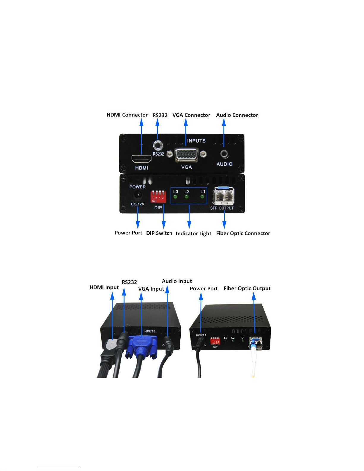
If HDMI transmission is needed,please connect HDMI cable to the HDMI connector; if
VGA transmission is needed, please connect VGA cable to the VGA connector. Please
note that HDMIandVGA cannot be transmitted at the same time.
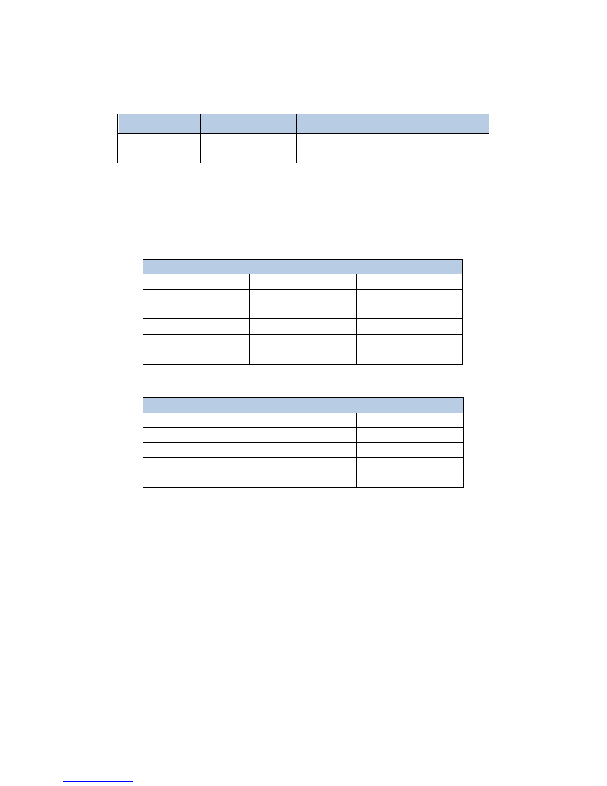
3. DIP Switch
Dial up is “OFF”, the corresponding number is “1”; dial down is “ON”, the corresponding
number is “0”. The DIP switch operating instructions as shown in Table 1.
Table 1 DIP switch operation instruction
DIP
Item
Description
Dial Switch 1
Function
Auto-correct switch when VGA input.
Applying
Condition
The HD-F01-TX is in service and the input mode is
VGA.
Operation
If the initial switch state is “ON”, dial it to “OFF”
first and then switch it to “ON” quickly (within 1s).
If the initial switch state is “OFF”, dial it to “ON”
first and then switch it to “OFF” quickly (within 1s).
Dial Switch 2
Function
To select HDMI input audio mode.
Applying
Condition
Before applying power to the HD-F01-TX or during
the service of the item.
Operation
If the switch sate is “ON”, analog audio will be
selected as the input audio for HDMI video.
If the switch sate is “OFF”, HDMI audio will be
selected as the input audio for HDMI video.
Dial Switch 3
Function
To select VGA input audio mode.
Applying
Condition
Before applying power to the HD-F01-TX or during
the service of the item.
Operation
If the switch sate is “ON”, HDMI audio will be
selected as the input audio for VGA.
If the switch sate is “OFF”, analog audio will be
selected as the input audio for VGA.
Dial Switch 4
Function
To select VGA/HDMI input mode.
Applying
Condition
Before applying power to the HD-F01-TX or during
the service of the item
Operation
If the switch is “ON”, VGA input is available.
If the switch is “OFF”, HDMI input is available.
Note: Input audio of signal source canbe embedded through the serial port.

HD-F01-TX UserManual
3
4. Indicator Light
Table 2 Indicator light and signal state
Light State
L1 on
L2 on
L3 flash
Description
HDMI Input
VGA Input
The HD-F01-TX
works normally.
5. Supported Resolutions
The supported resolutions of HDMI/VGAtransmission mode as shown in table 3 and table 4
respectively.
Table 3 Supported resolution of HDMI input
Table 4 Supported resolution of VGA input
VGA Input Mode
800×600@60Hz
1024×768@60Hz
1280×720@60Hz
1280×768@60Hz
1280×800@60Hz
1280×960@ 60Hz
1280×1024@60Hz
1360×768@60Hz
1366×768@60Hz
1440×900@60Hz
1400×1050@60Hz
1600×900@60Hz
1600×1200@60Hz
1680×1050@60Hz
1920×1080@60Hz
6. Audio Input
Audio transmission is available in two modes as below:
(1) Analog audio input, which canbe embedded with VGA or HDMI.
(2) HDMI digital audio input, which is transmitted by HDMI video synchronously. Itcanalso
be de-embeddedfrom HDMI and embedded with VGA.
Note:
Audio can not be transmitted separately.
VGA/HDMI signal transmission without audio is available.
7. Applying Power
First, please make sure that all the connection is fine.
Second, make all the configuration completed according to your specific needs.
Third, applying stable 12V/2Apower toboth the transmitter and the receiver.
HDMI Input Mode
800×600@60Hz
1024×768@60Hz
1280×720@60Hz
1280×768@60Hz
1280×800@60Hz
1280×960@60Hz
1280×1024@60Hz
1360×768@60Hz
1366×768@60Hz
1400×1050@60Hz
1440×900@60Hz
1600×900@60Hz
1600×1200@60Hz
1680×1050@60Hz
1920×1080@60Hz
1920×1200@60Hz
—
—

HD-F01-TX UserManual
4
8. OSD Setting
Step 1: Connect the HD-F01-TX to the control computer by using serial cable that comes
with the item. (The serial cable contains one 3.5 mm ear jack male connector andone DB9
pin female connector.)
Step 2: Putthe CD into the control computer. Decompress the configuration tool folder that
burned in the CD and install the tool. (You canalso askthe technical specialist for the
configuration tool folder.)
Step 3: Double-click the configuration tool will enter into the Communication
Setting interface. Select the serial port and baud rate as shown in figure 3.After that, click the
OK button.
Figure 3 Communication setting interface
Step 4: OSD setting main interface will show up after click the OK button in step3. OSD
setting is available in text andimage mode.
Image size is required to be less than 16K.
Text should not exceedthe software preview display.
Image format is available in bmp, jpg and jpeg.
Color setting is available in background and foreground.
Details as shown in figure 4.

HD-F01-TX UserManual
5
Figure 4 OSD setting main interface
Image mode settingstepsare as follows:
Step 1: Click the checkbox which is in front of the Enable OSD.
Step 2: Set the background image according to your specific needs. Please note that this step
is optional.
Step 3: Set the color of the image.
Step 4: Set the location andthe size of image.
Step 5: Select the magnification.
Step 6: Click the Downloadbutton and the setting will come into effect immediately.
Details as shown in figure 5.

HD-F01-TX UserManual
6
Figure 5 Image mode setting steps
Text mode settingsteps are as follows:
Step 1: Click the checkbox which is in front of the Enable OSD.
Step 2: Design the text content according to your needs.
Step 3: Set the color of text.
Step 4: Set the location andthe size of image.
Step 5: Select the magnification.
Step 6: Click the Downloadbutton and the setting will come into effect immediately.
Details as shown in figure 6.

HD-F01-TX UserManual
7
Figure 6 Text mode setting steps
Note: If OSD setting is not required, please uncheck the option which is in front ofthe
Enable OSD.
9. Parameter Setting
Parameter settingof the HD-F01-TX canhelp user select the control mode as well as the
audio input mode according to their actualapplication requirements. Details as shown in
figure 7 below.

HD-F01-TX UserManual
8
Figure 7 Parameter setting interface
Note:
If you would like to checkthe currentsate of the item, please click the Load button.
If the control mode is Dial Switch, the resolution of the item canbe configured by DIP
switch directly.
Important OSD information canbe savedto the local computer through the configuration
tool.
Table of contents
Other 4KDVB Extender manuals