4O3A Signature ANTENNA GENIUS 8x2 v2 PLUS User manual

ANTENNA GENIUS
User Manual
Software Version 4.1.0 - rev 1

4O3A Signature – Antenna Genius User Manual
Index Page 1 of 56
TABLE OF CONTENTS
TABLE OF CONTENTS .......................................................................................................................1
1. WELCOME................................................................................................................................3
1.1. Software Version 4.1............................................................................................................3
1.2. Considerations Before Upgrading........................................................................................4
1.3. Backing Up Your Configuration............................................................................................5
2. SPECS & FEATURES ..................................................................................................................7
3. LEGAL.......................................................................................................................................8
3.1. Radio & Television interference........................................................................................8
3.2. European Community CE conformity ...............................................................................8
3.3. Product updates................................................................................................................9
3.4. Limited warranty...............................................................................................................9
3.5. Trademarks .....................................................................................................................10
3.6. Copyright ........................................................................................................................10
4. WHAT CAN ANTENNA GENIUStm DO? ...................................................................................11
4.1. Multiple control options.................................................................................................11
4.2. SO2R and multi-op with a single FLEX-6000...................................................................11
5. HOW IT WORKS .....................................................................................................................13
5.1. Tech.................................................................................................................................13
5.2. Hardware ........................................................................................................................13
5.3. Software..........................................................................................................................13
5.4. FlexRadio Ecosystem.......................................................................................................13
6. ONLINE RESOURCES ..............................................................................................................14
7. WHAT COMES IN THE BOX?...................................................................................................14
8. HARDWARE............................................................................................................................15
8.1. Front panel......................................................................................................................15
8.2. Bottom panel..................................................................................................................15
8.3. Top panel ........................................................................................................................16
8.4. Where to put it? .............................................................................................................16
8.5. DC power connection .....................................................................................................18
8.6. Network cabling..............................................................................................................18
8.7. DIP Switch configurations...............................................................................................19
8.8. LAN Control Mode ..........................................................................................................21
8.9. BCD Control Mode..........................................................................................................23
8.10. Pin-2-Port Control Mode.............................................................................................24
8.11. Automatic Mode .........................................................................................................26
8.12. Manual Mode..............................................................................................................27
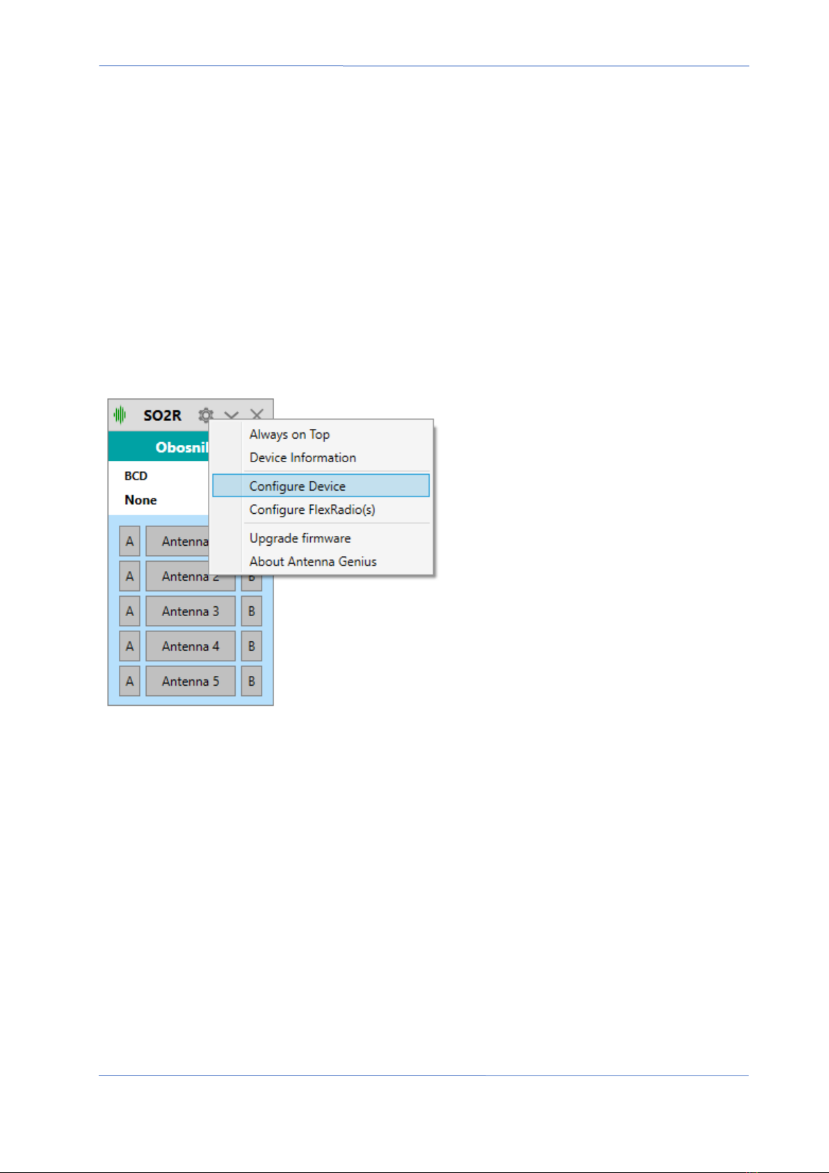
9. ANTENNA GENIUStm APP.......................................................................................................27
9.1. Initial set-up....................................................................................................................28
9.2. Device Information .........................................................................................................32
9.3. Is your firmware up-to-date?..........................................................................................34

4O3A Signature – Antenna Genius User Manual
Index Page 2 of 56
9.4. Initial Configuration........................................................................................................37
9.5. The Configuration Menu.................................................................................................37
9.6. Always On Top.................................................................................................................38
9.7. View Output Relays.........................................................................................................38
9.8. Device Settings................................................................................................................39
9.8.1. Basic Information ........................................................................................................39
9.8.2. Antennas......................................................................................................................40
9.8.3. Individual Antenna Settings - Bands, TX/RX/INB.........................................................40
9.8.4. Output Relays Designer...............................................................................................41
9.8.5. Output Groups.............................................................................................................42
9.8.6. Keyboard Shortucuts...................................................................................................45
9.8.7. Bands Range Configuration.........................................................................................46
9.8.8. FlexRadio .....................................................................................................................46
9.8.9. BCD..............................................................................................................................47
9.8.10. PTP.............................................................................................................................48
9.8.11. Network Settings.......................................................................................................48
9.8.12. Stacking .....................................................................................................................49
9.8.13. Advanced Options .....................................................................................................50
9.8.14. Static Entries / Remote Operation ............................................................................51
9.8.15. Auto Connect on Startup...........................................................................................52
9.9. Network Considerations .................................................................................................52
10. OPERATION.........................................................................................................................53
11. ADDITIONAL FEATURES ......................................................................................................53
11.1. Output Module Relay Control.....................................................................................53
12. TROUBLESHOOTING ...........................................................................................................55
12.1. Re-riving a bricked device ...........................................................................................55
13. CHANGELOG .......................................................................................................................56

4O3A Signature – Antenna Genius User Manual
Index Page 3 of 56
1. WELCOME
Congratulations on your purchase of an Antenna GeniusTM 8x2 v2 Plus Network-Enabled
(TCP/IP) High-Isolation Antenna Switch, a member of the 4O3A Genius SystemTM advanced
station automation line including Power GeniusTM, Rotator GeniusTM, and Tuner GeniusTM. More
information on these products can be found at:
https://4o3a.com/products/genius-family
GENIUS TIP! Antenna GeniusTM is sometimes abbreviated as “AG” in this document.
AG is at home in all types of ham shacks: contest stations extravagant and modest, from single
op to SO2R to full blown Multi-Multi, DXers, remote operators controlling their station from
their living room via LAN or over the Internet from a hotel room thousands of miles away, to
anyone wanting a better organized and more efficient station.
1.1. Software Version 4.1
This is the user manual for the new generation of Antenna Genius software - Version 4. This
version is completely rewritten from scratch with the focus on stability, reliability, and a
significant extension in features.
Just for clarification I want to point out that version 4.1 is the first publicly available version
from the new generation. Version 4.0 was never released to the public and was used for
extensive beta testing.
The new firmware has been designed to ensure that your Antenna Genius device operates
optimally, with improved performance and an expanded range of capabilities. Our team of
developers have spent countless hours working on this version to ensure that it is as solid and
as stable as possible. This firmware version will provide you with a seamless experience, with
minimal downtime or unexpected errors.
Fully compatible with all previous hardware versions of Antenna Genius. This means that you
can upgrade to Version 4 with ease, and enjoy the new features without worrying about
compatibility issues. Whether you are using the latest hardware or an older device, you can be
sure that this firmware will work seamlessly with your system.
With Version 4.1, you can expect a significant extension in features, including enhanced
capabilities, improved performance, and a more user-friendly interface. We have taken great
care to ensure that this firmware is easy to use and navigate, even for those who may not be
familiar with technical terminology. Whether you are a beginner or an experienced user, you
can be confident that this firmware version will meet your needs.

4O3A Signature – Antenna Genius User Manual
Index Page 4 of 56
We are committed to providing our users with the best possible experience, and this new
version of Antenna Genius firmware is a testament to our dedication to excellence. We are
confident that this new firmware will exceed your expectations and provide you with an even
better experience than before. We encourage you to explore the new features and capabilities
of Version 4 and discover the benefits of this latest release.
1.2. Considerations Before Upgrading
Important! The API and network protocol for this version have been completely
redesigned and rewritten so any custom software that worked previously will not be
compatible with new version out of the box, and will need to be updated.
If you have any third-party software or hardware integrated with your AG do not upgrade
before checking if your software has been updated to be compatible with the version 4.
We put in a great deal of effort to ensure that the new API and network protocol are
more reliable, easier to use, and offer enhanced functionality.
The new API is publicly available, and we encourage anyone who wants to use it to
refer to https://github.com/4o3a/genius-api-docs/wiki/Antenna-Genius-API for more
information. Our website provides comprehensive documentation and resources that
can help you get started with the new API and network protocol, as well as troubleshoot
any issues that may arise.
While we understand that the transition to the new API and protocol may take some
time, we are confident that the benefits of this update will be well worth the effort. We
have taken great care to ensure that the new API is more efficient and user-friendly, with
enhanced functionality that will provide a better overall user experience.
We would like to thank our users for their continued support and patience during this
transition period. We are committed to providing you with the best possible experience,
and we believe that this new version of the API and network protocol will help us
achieve that goal. If you have any questions or concerns about this update, please do
not hesitate to contact our support team for assistance.

4O3A Signature – Antenna Genius User Manual
Index Page 5 of 56
1.3. Backing Up Your Configuration
Important! During the process of upgrading to the new firmware the configuration
will be lost.
However, the new version is completely backwards compatible with the previous
generation configuration file.
The configuration is stored in the memory on-board the Antenna Genius but it can be
backed up into an XML configuration file stored on your PC.
In order to back up your configuration:
1. Go to the configuration menu of your
Antenna Genius.

4O3A Signature – Antenna Genius User Manual
Index Page 7 of 56
2. SPECS & FEATURES
Manufacturer 4O3A SignatureTM by Sky Sat d.o.o.
Model Antenna GeniusTM 8x2 Plus v2
Functionality 8 antenna 2 radio RF matrix switch controlled via TCP/IP (LAN or WAN),
BCD, or +12 VDC Pin-To-Port
RF connectors UHF female (SO-239) standard, N female available by special order
Power handling → 3,000 Watts ICAS (SSB/CW) for 5 minutes @ 1.5:1 VSWR @ 30 MHz
→ 1,000 Watts ICAS (SSB/CW) for 3 minutes @ 1.5:1 VSWR @ 50 MHz
Ports → RJ-45 (LAN)
→ two DE-15 VGA-type (BCD band data or +12 VDC pin-to-port)
Network 100Base-T Fast Ethernet (100-Mbps), DHCP or manually-assigned
network address, TCP/IP
Power consumption 300 mA @ 13.8 VDC
Frequency range DC through 55 MHz
Port-to-port isolation → 90dB between ports worst case @ 14 MHz
→ 80dB between ports worst case @ 30 MHz
→ 70dB between ports worst case @ 50 MHz
CPU Microchip Technology 32-bit PIC processor
Automation Windows App, FlexRadio Systems SmartSDR API, Genius System devices,
BCD, Pin-to-Port
Features → hardware interlock prevents two radios connecting to same antenna
→ unselected antenna ports grounded
→ LEDs indicate antenna ports in use
→ firmware updates via LAN
Case rugged stainless steel chassis with wall mount flanges top and bottom
Dimensions 6.75” W x 13.25” H x 3.25” D including mounting flanges (21 x 17 x 6 cm)
Net weight approx. 4.4 lbs. (approx. 2 kg)

4O3A Signature – Antenna Genius User Manual
Index Page 8 of 56
3. LEGAL
3.1. Radio & Television interference
(FCC Part 15 - §15.21 and §15.105)
This equipment has been tested and found to comply with the limits for a Class B digital device,
pursuant to part 15 of the FCC Rules. These limits are designed to provide reasonable
protection against harmful interference in a residential installation. This equipment generates,
uses and can radiate radio frequency energy and, if not installed and used in accordance with
the instructions, may cause harmful interference to radio communications. However, there is no
guarantee that interference will not occur in a particular installation. If this equipment does
cause harmful interference to radio or television reception, which can be determined by turning
the equipment off and on, the user is encouraged to try to correct the interference by one or
more of the following measures:
Reorient or relocate the receiving antenna.
Increase the separation between the equipment and receiver.
Connect the equipment into an outlet on a circuit different from that to which the receiver is
connected.
Consult the dealer or an experienced radio/TV technician for help.
You may also find the following FCC booklet helpful: "How to Identify and Resolve Radio-TV
Interference Problems" available from the U.S. Government Printing Office, Washington D.C.
20402. Info also available online at FCC.gov:
https://www.fcc.gov/guides/interference-defining-source
Changes and Modifications not expressly approved by the manufacturer or registrant of this
equipment can void your authority to operate this equipment under Federal Communications
Commission’s rules.
3.2. European Community CE conformity
Sky Sat d.o.o. declares Antenna GeniusTM 8x2 complies with the European Community EMC
standards:

4O3A Signature – Antenna Genius User Manual
Index Page 9 of 56
ETSI EN 300 330-1
ETSI EN 300 489-1
ETSI EN 300 489-15
CE compliance reports are available upon written request to Sky Sat d.o.o.
3.3. Product updates
Sky Sat d.o.o. reserves the right to make hardware and/or software product improvement or
manufacturing changes without notice or any obligation to update units previously sold.
3.4. Limited warranty
This product is warranted to be free of defects in materials and workmanship for one year from
the date of purchase. Sky Sat d.o.o. will repair or replace, at our option, any equipment proven
to be defective within the warranty period. Warranty F.O.B. Sky Sat d.o.o., Ratiševina bb, Igalo
85347, Montenegro. Please contact the appropriate party for your region and obtain a return
authorization (RA) number before returning any product for warranty service. RA number must
be indicated on box used to return product for service.
What is covered: During the first year after date of purchase, 4O3A Signature will replace
defective parts free of charge (post-paid) for AG components only. Any replacement hardware
parts will be warranted for the remainder of the original warranty period or ninety (90) calendar
days from the date of installation or repair, whichever is longer. 4O3A Signature will also correct
any failure caused by defective parts and materials. The complete unit must be sent to 4O3A
Signature at your expense in the original shipping container or other packaging sufficient to
prevent damage in transit. 4O3A Signature is not responsible for damage or lost shipments from
the customer. 4O3A Signature will insure the package and pay return shipping.
What is not covered: This Limited Warranty as it pertains to the Antenna Genius or components
does not cover repair or damage caused by (1) misuse, negligence or user modifications; (2) any
performance malfunctions involving non-4O3A Signature equipment; (3) connection to
improper or unstable voltage supply; (4) the incorrect installation of any and all cables
connected to the radio by the user; (5) the use of third-party software applications or hardware
that directly or indirectly controls AG functions and/or operating state by utilizing a
communication or control protocol, such as, but not limited to CAT or I2C commands, or (6)
random acts of nature such as flood, fire, water, weather related storm, lightning or
electrostatic discharge damage.
Limitation of Incidental or Consequential Damages: This warranty does not extend to non-
4O3A Signature equipment or components used in conjunction with our products. Any such
repair or replacement is the responsibility of the customer. 4O3A Signature will not be liable or

4O3A Signature – Antenna Genius User Manual
Index Page 10 of 56
responsible for reimbursement for any special, indirect, incidental or consequential damages,
including but not limited to any loss of business or profits, loss of property, loss of revenue, loss
of use, loss of data, inconvenience or cost of unauthorized service.
3.5. Trademarks
4O3A SignatureTM, Antenna GeniusTM, Rotator GeniusTM, Station GeniusTM, Interface GeniusTM,
and 4O3A Genius SystemTM are trademarks of Sky Sat d.o.o.
FlexRadio SystemsTM and SmartSDRTM are trademarks of Bronze Bear Communications, Inc.
d/b/a FlexRadio Systems.
PIC32TM is a trademark of Microchip Technology Inc.
All other products, company names, brand names, and trademarks are the property of their
respective owners.
3.6. Copyright
This publication Copyright © 2015-2023 by Sky Sat d.o.o. All rights reserved. May not be
reproduced in part or in whole without Sky Sat d.o.o.’s prior written permission.

4O3A Signature – Antenna Genius User Manual
Index Page 11 of 56
4. WHAT CAN ANTENNA GENIUStm DO?
Antenna Geniustm 8x2 v2 Plus is a matrix antenna switch which can route eight antennas to two
radios using a variety of control methods. Software and hardware interlocks - double protection
- prevent the same antenna from being connected to both radios. This, along with AG’s ultra-
high port-to-port isolation help protect your radios from front end damage.
s
AG in action with SmartSDR @ 4O3A (AG Always on top option engaged)
4.1. Multiple control options
You have five ways to control your AG:
1. FlexRadio over your TCP/IP network; AG will automatically follow two different Slice
band selections and obtain band data from them
2. Manual band switching from the AG Windows app connected via your network
3. BCD (Binary-Coded Decimal) signals via the DE-15 VGA-style connector from any radio
(Yaesu, Elecraft…)
4. +12 VDC “Pin-to-Port” via the DE-15 VGA-style connector
4.2. SO2R and multi-op with a single FLEX-6000
AG’s extreme port-to-port isolation is perfect for SO2R (Single Operator 2 Radio) contesting with
a single Flex rig! With AG, you can operate SO2R with one radio using a single FLEX-6600 or
FLEX-6700 transceiver in full duplex mode. In other words, the ‘two radios’ in SO2R are both
inside your single Flex rig!

4O3A Signature – Antenna Genius User Manual
Index Page 12 of 56
GENIUS TIP! All 4O3A Genius Systemtm products use standard TCP/IP protocols to communicate with
each other and with other suitably-equipped devices. The 4O3A Signature team believes in open
standards in ham radio and makes its APIs (library of commands) available freely to other
manufacturers and software authors.

4O3A Signature – Antenna Genius User Manual
Index Page 13 of 56
5. HOW IT WORKS
Antenna Genius brings together a powerful CPU, fast network interface, rugged, high power
relays and a programming/control App that runs in all supported versions of Windows. We are
confident AG is the best antenna switch you can buy.
5.1. Tech
AG is powered by a Microchip Technology PIC32 microprocessor, a 32-bit device. Why so much
horsepower in an antenna switch? Advanced technology radios demand high-horsepower
accessories! Also, the extra computing power enables the addition of new features via firmware
updates in the future.
AG has 100BASE-T networking built-in. Based on the Ethernet standard. but ten times faster
than 10BASE-T, it is often referred to as Fast Ethernet. Officially, the 100BASE-T standard is IEEE
802.3u. 100BASE-T devices will also work fine on older 10BASE-T networks albeit at slower
speeds.
5.2. Hardware
AG uses high quality 16 Amp relays rated at 12,800 W DC and conservatively rated for 1,000 W
RF at up to 50 MHz. AG’s relays are used for RF switching and also for the hardware lockout that
prevents two radios from being connected to the same antenna (there is also a software lockout
for redundant protection). The design priority was maximum port-to-port isolation coupled with
power handling ‘headroom’ - twice legal limit at high duty cycle - to enable reliable, long term
operation.
5.3. Software
The AG App runs on all Microsoft-supported versions of Windows and is an integral part of the
AG system. You will use the AG App for initial set up and programming of your AG and also for
alternate antenna selection when you have more than antenna available for a particular band.
The AG App can also serve as your AG control interface if you don’t want automatic band
selection controlled by FlexRadio Slice band changes.
5.4. FlexRadio Ecosystem
In the “FLEX-6000 Signature Series Ecosystem,” the AG App collects frequency and other data
directly from the SmartSDR (SSDR) API, a software-to-software connection performed inside
your PC or over your LAN at very high speed. No RS-232 cables to set up, no “stop bits,” nor
lethargic baud rates. It is a truly modern, intelligent, and high-speed solution.
AG will monitor any two SSDR Slices to determine the bands in use and use this data to select
the appropriate antenna(s) for each Slice.

4O3A Signature – Antenna Genius User Manual
Index Page 14 of 56
6. ONLINE RESOURCES
4O3A Genius SystemTM owners have many online resources available to help them fully realize
the capability of their Antenna GeniusTM, Rotator GeniusTM, Tuner GeniusTM and more.
4O3A Web Site Downloads: current owners manuals, white papers, Apps, firmware, and
changelog are available at:
https://4o3a.com/support/downloads
4O3A Web Site Forum:
https://4o3a.com/support/forum
FlexRadio Systems Community: a great resource for anything related to FLEX-6000 Signature
SeriesTM, SmartSDRTM and MaestroTM:
https://community.flexradio.com/flexradio/
EXPERT TIP! Join the 4O3A Signature Web Site Forum 4O3A or 4O3A Genius Products Google Group
or to stay up-to-date, network with other users, and get helpful tips:
Google Group: or
4O3A Signature Web Site Forum:
7. WHAT COMES IN THE BOX?
When you unpack your AG box you should have:
•Antenna Genius
•DC power connectors
•Quick-start Guide
•Other items, such as LAN, DC and coax cables, are user supplied
•Owner’s Manual (this document) and other documentation is available for free
download from:
https://4o3a.com/support/downloads

4O3A Signature – Antenna Genius User Manual
Index Page 15 of 56
8. HARDWARE
EXPERT TIP! Read this and the following Software section carefully before changing any DIP switches
or software settings.
8.1. Front panel
Front panel features:
•SO-239 (or N-female) connector for Port A
•SO-239 (or N-female) connector for Port B
•8 SO-239 (or N-female) connectors for antenna inputs
•LEDs: red LEDs indicate which A port antenna has been selected and green LEDs indicate
which B port antenna is selected
8.2. Bottom panel
Bottom panel features:
•LAN: RJ-45 jack connects to your home/shack network (assumes you are using the
network control option as most Flex users will be)
•Two DE-15 VGA-type for users opting for BCD or +12 VDC pin-to-port control in lieu of
network control, for controlling standard radios as Yaesu, Elecraft etc. These are left
unconnected if you are using network control (most FlexRadio equipped stations won’t
use these ports)
•12-15VDC: connect your shack 13.8 VDC power supply here paying attention to proper
polarity, anywhere from 12 to 15 VDC with at least 300 mA will be OK
•OM module: enables connecting the 16 relay Output Module for station automation
•DIP Switches: The side panel has 8 DIP switches for resetting the configuration.
AG can be controlled four different ways: (1) LAN, (2) BCD, (3) Pin-to-Port. The control mode is
set independently for Port A (Radio A) and Port B (Radio B) by the DIP switches. For example,
Port A could be controlled over the network and Port B could be controlled by BCD signals.

4O3A Signature – Antenna Genius User Manual
Index Page 16 of 56
8.3. Top panel
The top panel features:
•A DC power connector for stacking multiple AG units. This enables a single switch to
switching between 16, 24 or 32 antennas.
•Two pairs of dedicated PTT input and output RCA ports for hot switching protection.
There are independent ports for both A and B radio.
•Red LED for indication that Port A protection is engaged. Green LED for indication that
Port B protection is engaged.
8.4. Where to put it?
Most users will install AG near their station bulkhead, the location where their antenna feed
lines, AC mains, DSL, cable TV, and/or other cables enter the shack and where the single point
ground system nexus is located (you do have a single point ground system, don’t you?). Locating
AG at your bulkhead or other remote location means only three cables need to be run to the
station operating position, coax for the A and B radios and a Cat5e (or higher) Ethernet cable for
the LAN (if not using LAN, you will need a pair of control lines, one for Port A and for Port B).
At the left side is the bulkhead-sited AG @ W0LFA prior to connection of coax lines and ground

4O3A Signature – Antenna Genius User Manual
Index Page 17 of 56
connection:
AG can also be installed at the operating position or outdoors. If the later, install AG in an
outdoor NEMA-rated enclosure and make sure it has a ‘weep hole” at the bottom to allow air
circulation and to let moisture out.
The picture on the right is an AG installed outdoors in very unfriendly conditions (temperatures
down to -28 °C (-17.6 °F) in Minnesota @ W0AD.
EXPERT TIP! Reduce station clutter by mounting your AG near your station cable entrance
“bulkhead.” Slots for such mounting are provided on the top of the AG case.
AG is a 100BASE-T network device using standard TCP/IP protocols, it is therefore subject to the
usual 328-foot (100m) LAN cable run limitations per TIA/EIA 568-5-A. If longer runs are
required, the use of intermediate active hardware such as a repeater or switch will be
necessary. Cat5e cable is recommended, and higher-rated cables such as Cat6 are also OK.
EXPERT TIP! For outdoor UTP (Ethernet) cable runs, be sure to use outdoor-rated cable including
UV-resistance properties if located in direct sunlight.
4O3A Signature encourages all amateur radio operators to employ single point ground systems
for both protection from lightning induced power surges and also for RFI mitigation. A good

4O3A Signature – Antenna Genius User Manual
Index Page 18 of 56
source for information on this topic is the ARRL Handbook, updated annually and available from
the ARRL Bookstore:
https://arrl.org
Another excellent resource for station grounding information and RFI mitigation are several
documents written by Jim Brown, K9YC, available for free download at:
http://www.audiosystemsgroup.com/K9YC/K9YC-old
AG is a computer and thus its electronics will generate some heat. Also, the relays and other
components will generate heat when under load. Make sure there is adequate clearance and
airflow around the AG cabinet sides and top in its installation position.
8.5. DC power connection
Connect a DC power cable from your station 13.8 VDC power supply (anywhere from 12 to 15
VDC is OK, your shack DC power supply is likely 13.8 VDC) to the outlet marked 12-15VDC on
the bottom panel. Center pin is + pole. We recommend using a DC fuse such as those provided
on the popular RIGrunner and similar DC power distribution units (you can use the 1 Amp blade
fuse that comes with RIGrunners). If you don’t have a RIGrunner, we strongly suggest you place
a 1 Amp DC fuse in series with the hot side of your DC power cable.
Make sure your power supply can supply at least 300 mA @ 13.8 VDC. We strongly advise using
a clean, high-quality DC power source for AG and all your other station equipment. Many cheap
switch mode power supplies and “wall warts” are unstable and can generate surprising
amounts of RFI well into the VHF spectrum.
8.6. Network cabling
Most home networks (LAN) operate at Ethernet (10 Mb/s), Fast Ethernet (100 Mb/s) or Gigabit
Ethernet (1000 Mb/s) speeds. All of these networks work fine over Category 5 UTP or better
rated cable such as Cat5e, which is widely available, or Cat6. It’s likely the cable you are already
using for your home network will work great with AG.
If you are unfamiliar with or need a refresher on home networks, a good primer from PC World
is online here:
http://www.pcworld.com/article/196049/the_ultimate_guide_to_home_networking.html
100BASE-T networking has 328-foot (100 m) limitation between active devices (such as Ethernet
switches). Keep this in mind when locating your AG.

4O3A Signature – Antenna Genius User Manual
Index Page 19 of 56
Use a Cat5e, Cat6 or Cat6a UTP cable (not supplied, please don’t use a cheap cable here; poor-
quality high-speed data cables are never a good idea!) between the Ethernet port on your AG
and your station LAN switch or hub (switches preferred over hubs). This should be the same
place where your FLEX-6000 Signature Series radio connects to your LAN. Note this LAN
connection can be as simple as a port on a DSL router or as fancy as a standalone Gigabit switch.
AG can be controlled by PCs connected over WiFi to your LAN as long as AG itself is connected
directly to your LAN via a wired connection to an Ethernet switch or hub (switch recommended;
Ethernet hubs will slow down your LAN).
8.7. DIP Switch configurations
As of version 4.1.0. DIP switches are no longer used to configure band data sources, ID or group
ID.
Important: All these settings are now done through the Windows app utility program and the
position of DIP switches 1 through 6 doesn’t do anything.
DIP 7 is used to reset your AG config settings to default and sets the IP setting to DHCP (see
Section 9.2 below).
DIP 7
ON
restore factory settings on next power cycle
OFF
normal operation
To reset AG configuration and IP settings follow these steps in order:
1. remove DC power from AG
2. move DIP 7 to ON position
3. turn DC power back on
4. move DIP 7 back to OFF position
DIP 8 is used to force your AG into bootloader mode to enable you to re-upload the firmware
to the device.
This is used when your AG gets bricked (unresponsive) for whatever reason – due to
configuration, power failure in some critical state tetc.
Table of contents
Other 4O3A Switch manuals
Popular Switch manuals by other brands

EnOcean
EnOcean Easyfit EWSSB user manual

D-Link
D-Link DGS-3100-24 Specifications

Knauer
Knauer Azura VU 4.1 instructions

AMX
AMX Solecis AVS-SL-PR-0201-0301 installation guide

Larson Electronics
Larson Electronics PDU-ATS-100A-208Y.120-3PH instruction manual

Edimax
Edimax ES-3305P V2 Declaration of conformity