89 North LDI-6 User manual

15000-MNL-01 Rev A 1
LDI-6/7
Operating Manual
This manual contains important information necessary for the safe and efficient operation of the LDI light source
system. Please read the manual in its entirety and heed all safety warnings before operating the light source.
Follow all safety precautions!
DANGER –LASER RADIATION
AVOID EYE OR SKIN EXPOSURE TO DIRECT OR SCATTERED RADIATION
CLASS 4 LASER PRODUCT
The 89 North® LDI (15000-000-000-XX) light source system is designed and tested in accordance with IEC 61010-
1, CAN/CSA C22.2 Number 61010-1, CENELEC EN 61326-1:2006, and FCC Part 15 Subpart B, Class B.
Prior to use, carefully unpack and inspect all components for any signs of damage which may have occurred during
shipping. If shipping damage is suspected, notify 89 North or your authorized 89 North distributor immediately.
89 North customer service or your authorized 89 North distributor should be informed immediately in the event
of any damage or malfunction in the equipment.
89 North®
20 Winter Sport Lane, Suite 135
Williston, VT 05495
U.S.A.
877-417-8313
+1-802-881-0302
www.89north.com

15000-MNL-01 Rev A 2
Contents
1 Document Symbols ............................................................................................................................................3
2 Equipment Symbol Definition ............................................................................................................................4
3 Specifications......................................................................................................................................................5
4 Introduction and Intended Use..........................................................................................................................5
5 Safety..................................................................................................................................................................6
6 System Overview................................................................................................................................................8
7 I/O Connections............................................................................................................................................... 13
8 Breakout Box (Optional).................................................................................................................................. 14
9 Initial Setup ..................................................................................................................................................... 15
10 Operation ........................................................................................................................................................ 20
11 Maintenance ................................................................................................................................................... 28
12 Troubleshooting .............................................................................................................................................. 28

15000-MNL-01 Rev A 3
1Document Symbols
Special instructions are emphasized as follows:
NOTE:
This term contains important information regarding set-up and operation to facilitate ease
of use and obtain effective results
This term contains critical information regarding safe handling and use of this system.
Device malfunction or property damage could result if these instructions are not followed.
WARNING:
This term contains critical information by identifying conditions or practices that may result
in injury or loss of life if these instructions are not followed.

15000-MNL-01 Rev A 4
2Equipment Symbol Definition
Caution - Risk of electric shock
This symbol indicates there are hazardous electrical parts
inside the equipment.
Caution - Risk of danger
This symbol indicates that safe handling and usage
instructions must be followed to avoid injury and/or damage.
DANGER –LASER RADIATION
AVOID EYE OR SKIN EXPOSURE TO DIRECT OF
SCATTERED RADIATION
CLASS 4 LASER PRODUCT
IEC 60825-1:2014-05
Maximum Output: 2W
Emitted Wavelengths: 398nm-643nm
AVOID EXPOSURE –LASER RADIATION IS
EMITTED FROM THIS APERTURE
This symbol indicates that Class 4 laser radiation emits from
the aperture to which this label is closely affixed.
CAUTION –CLASS 4 VISIBLE AND INVISIBLE
LASER RADIATION WHEN OPEN AND INTERLOCKS
DEFEATED. AVOID EYE OR SKIN EXPOSURE TO
DIRECT OR SCATTERED RADIATION.
This label indicates that removal of the panel to which this
label is affixed will permit laser radiation in excess of Class 3B
when interlocks are failed or defeated.
DANGER –OPTIONALLY INTERLOCKED
PROTECTIVE HOUSING PANEL
Visible and/or invisible laser radiation when open
and interlock failed or defeated. Avoid eye or skin
exposure to direct or scattered radiation.
This label indicates that removal of the panel to which this
label is affixed will permit laser radiation in excess of Class 3B
when interlocks are failed or defeated.
See section 6 for locations of each label.

15000-MNL-01 Rev A 5
3Specifications
Physical Specifications
Dimensions
Length: 33cm (12.9 inches)
Width: 15 cm (5.8 inches)
Height: 24 cm (9.5 inches)
Weight
~9 lbs
Operating Conditions
Required Clearance
15 cm (6 inches) around front and rear of unit
Operating Temperature
10-32°C / 50-90°F
Operating Humidity
<80% relative humidity, non-condensing
Power Supply
AC Input Power Requirements
100-240V AC, 50/60 Hz, 3.0 amps (maximum)
DC Input Power Requirements
24 VDC, 10.41A
Fuses
None
Optical
Spectral Range
398nm –643nm
Internal fiber, RGGBBV
400 m, .39 NA
Internal fiber, 555
400 m, .22 NA
External Output Fiber (supplied
or recommended)
400 m, .39 NA
Control Options
TTL
>2.3 V High
Analog
0-5V
USB-DSP
Virtual COM port –SDK available upon request
4Introduction and Intended Use
The LDI is a multi-wavelength laser-diode light source intended for use in fluorescence imaging
applications. The LDI is a standalone unit, designed to operate on a desk or bench and connect to a
microscopy instrument or other imaging equipment via optical fibers.
The LDI-6 has six discrete wavelength channels (RGGBBV) while the LDI-7 has seven (RGGBBV + 555nm).
The LDI-6 has one output aperture for all channels and the LDI-7 has two output apertures: one for
RGGBBV channels and another for the 555nm channel. 89 North supplies an optional 400 m bifurcated
fiber to combine the two LDI outputs into one fiber.
Because of its intense brightness, the LDI includes several safety interlocks that, when tripped, will block
the laser emission produced by the system. Do not override these interlocks. Doing so may result in injury
to the user and/or the unit and will immediately void the warranty.

15000-MNL-01 Rev A 6
5Safety
The LDI incorporates Class 4 lasers which produce heat as well as visible and UV light. Proper care must
be taken in setup and operation to prevent injury.
The laser emission output apertures are SMA-905 fiber connections which are located on a connector
panel in the ‘fiber access area’ of the LDI. The fiber access area is accessible by raising the interlocked fiber
access cover (see section 6).
Locations of apertures where laser radiation exceeding Class 1 AEL specifications is emitted are shown in
Figure 1:
1. SMA connector corresponding to the multicolor NovaLum RGGBBV laser
2. SMA connector corresponding to the 555 (Green Necsel) laser
Figure 1: SMA connectors with arrow 1 pointing to the RGGBV connector and arrow 2 pointing to the 555 connector.
The LDI incorporates safety interlocks which prevent laser emission when optical fibers are not installed
in the unit.
NOTE:
The LDI will not produce laser emission from an aperture unless an external output
fiber is installed.
The LDI incorporates a remote safety interlock which prevents laser emission when the connected remote
interlock is open.
The LDI incorporates a safety interlock which prevents the unit from being powered with the protective
cover removed.

15000-MNL-01 Rev A 7
Additionally, the LDI incorporates a safety interlock which prevents laser emission when the fiber access
cover is removed.
CAUTION –Use of controls or adjustments or performance of procedures other than
those specified herein may result in hazardous radiation exposure.
If the equipment is used in a manner not specified within this manual the protection
provided by the equipment may be impaired.
The fiber access cover should be removed for fiber installation or removal only. Removal
of the fiber access cover will result in lasers turning off.
WARNING:
Do not remove any covers except the fiber access cover. Removal of covers other than
the fiber access cover could expose the user to electrical hazards and moving parts and
will void the product warranty.
Do not operate the unit near any flammable materials including flammable gases or
liquids.
WARNING:
The light engine produces ultraviolet radiation. Never look directly at the output from
the optical fiber or at scattered laser light from any reflective surface.
WARNING:
Never operate the light engine with the optical fiber disconnected from the
fluorescence instrument as visible and invisible laser radiation can be harmful to the
unprotected eye and skin.
WARNING:
Use the laser in an enclosed room with restricted access.
WARNING:
The light engine produces significant amounts of heat. Ensure sufficient clearance
around the front and rear of the unit for proper cooling.
WARNING:
Never attempt to override safety interlocks or operate unit with interlocks overridden.

15000-MNL-01 Rev A 8
6System Overview
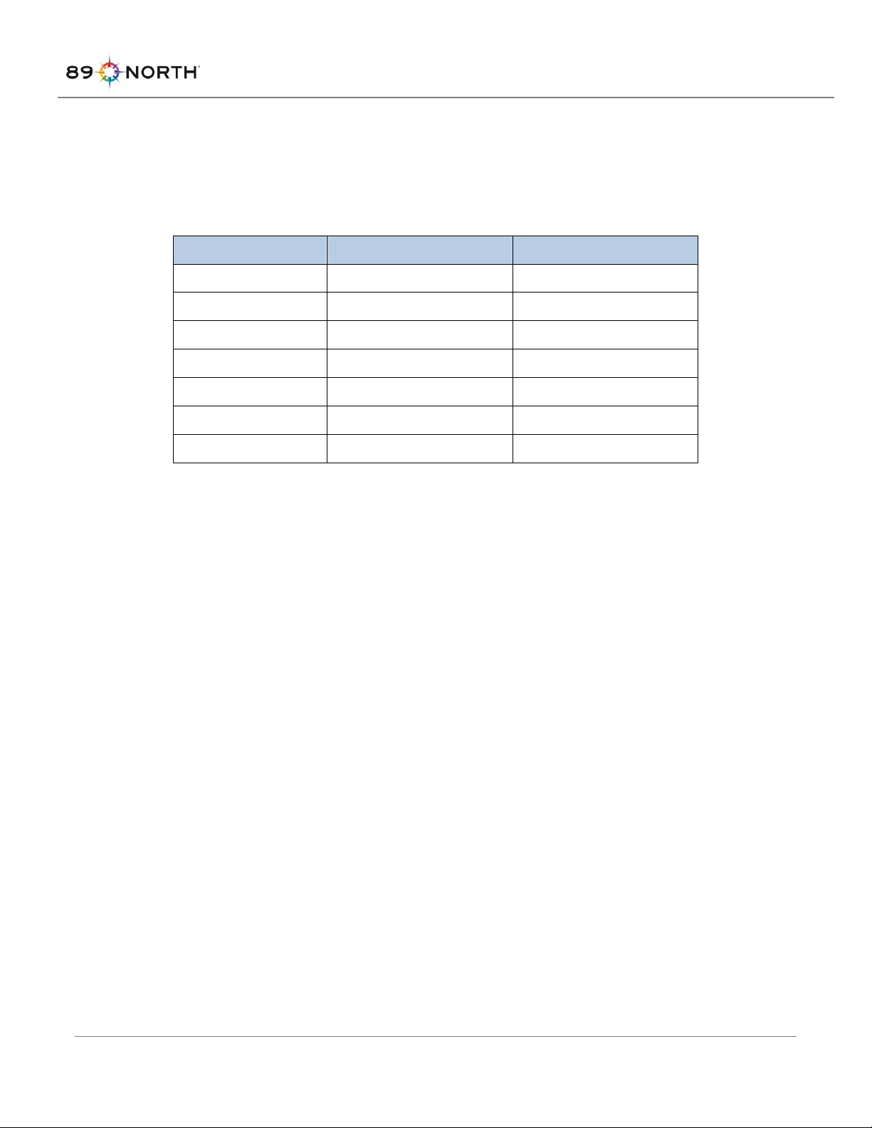
The LDI-6 has six laser lines while the LDI-7 has seven laser lines. Values of the maximum output power of
available laser lines in either pulsed or continuous operation are given in Table 1:
Table 1: Maximum output power values for each laser line.
Configuration
Center Wavelength (nm)
Max. Output Power (mW)
LDI-6, LDI-7
405
300
LDI-6, LDI-7
445
1000
LDI-6, LDI-7
470
1000
LDI-6, LDI-7
520
500
LDI-6, LDI-7
528
500
LDI-7
555
1000
LDI-6, LDI-7
640
500
Laser emission is delivered from the LDI through optical fibers which are connected to SMA optical
connectors on the top of the LDI in the fiber access area. For the LDI-6 and -7, one SMA output (right side
of unit when viewed from the front) corresponds to a multi-color laser diode module which contains the
six laser lines 405nm, 445nm, 470nm, 520nm, 528nm, 640nm. This output is labelled “RGGBBV” where
the fiber exits the LDI. On the LDI-7, a second SMA output (left side of unit when viewed from front)
corresponds to the 555nm laser line. This fiber output is labelled “555”.
Output beam divergence is dependent on the external output fiber installed.
The 555nm laser line can be pulsed up to 120Hz, 50% duty cycle at 100% intensity before performance
degradation is evident (4 msec pulse). The RGGBBV lines can be pulsed up to 8000 Hz, 50% duty cycle at
100% intensity before performance degradation is evident (0.625 msec pulse). ‘Performance degradation’
could be laser line failing to achieve full set intensity or irregularity of pulse shapes, depending on the
laser line and exact operating parameters. Laser diode lines cannot be overdriven for pulsed operation,
i.e. the maximum output powers above hold for continuous wave and pulsed operation.

15000-MNL-01 Rev A 9
LDI Overview Figures
LDI:
Figure 2: LDI Model

15000-MNL-01 Rev A 10
Front Panel Controls and Indicators:
Rear Panel Connections:
Figure 4: Front Panel
Figure 3: Rear Panel

15000-MNL-01 Rev A 11
Laser Safety Label Locations:
Figure 5: Laser Safety Labels, Interlocked Fiber Access Cover, Class 4 Laser
Figure 6: Laser Safety Labels, Apertures
Aperture Labels
(Fiber Access Cover Removed)

15000-MNL-01 Rev A 12
Figure 7: Laser Safety Label, Interlocked Cover

15000-MNL-01 Rev A 13
7I/O Connections
Serial I/O connection is made through the USB connector on the rear panel. Analog voltage and TTL signal
connections for intensity and shutter control are made via the DB25 connector on the rear panel:
Figure 8: DB25 Connector Pinout

15000-MNL-01 Rev A 14
8Breakout Box (Optional)
The optional ‘Breakout Box’ provides an external analog intensity control and TTL shutter control connections
for each of the channels in the LDI and routes them to the appropriate pins of the LDI interface connector.
The Breakout Box connects to the LDI unit with the supplied DB25 male to male cable. BNC connections are
provided to connect to the customer supplied equipment (BNC cables not included).
Figure 9: Breakout Box and Cable

15000-MNL-01 Rev A 15
9Initial Setup
System Components
The LDI-6/7 illumination system is comprised of:
•Laser light engine
•External power supply: AC-DC adapter
•Electrical power cord
•USB cable
•External output fibers (89 North supplied or customer supplied)
•LDI.exe graphical user interface
Carefully unpack all components.
Picking a Location
Place the LDI-6/7 on a flat, level surface, with its feet on the surface in the orientation shown in Figure 2.
Set the external power supply on a flat surface that allows for adequate ventilation on all sides. Maintain
6” (15 cm) of clearance on the front and rear of the LDI. Note that the clearance between The LDI and
other pieces of heat producing equipment should be increased to ensure that the heat from one unit does
not contaminate the required cooling air stream for the other.
NOTE:
Maintain at least 6” of clearance around the front and rear or the LDI for adequate
ventilation.
NOTE:
For proper temperature regulation, the LDI must be placed on a flat surface on its
feet.
Installing Output Fibers and Master Key
Remove the fiber access cover by pressing the fiber access cover release button and lifting the fiber access
cover (Figure 10). Remove the bag containing the master key, USB flash drive, remote interlock mating
connector, and SMA-SMA adapter (if ordered).

15000-MNL-01 Rev A 16
Figure 10. Top: LDI with the fiber access cover. Bottom: LDI without the fiber access cover.
Install the output fiber(s):
LDI-6: Remove the SMA cap from the SMA connector installed in fiber access area. Connect the output
fiber to the SMA connector. Route the fiber through the associated slot in the LDI front panel (Figure 11).
LDI-7: Remove the SMA caps from the SMA connectors installed in fiber access area. Connect output fibers
to the SMA connectors. Route the fibers or bifurcated fiber legs through the associated slots in the LDI
front panel (Figure 11). Note: If an output channel is not intended to be used, i.e. the output fiber for this
channel will not be installed, the SMA cap for that channel should remain in place.

15000-MNL-01 Rev A 17
Figure 11. Fiber routing slots in the front panel of the LDI.
Replace the fiber access cover by inserting the lip of the fiber access cover into the fiber access cover slot,
as shown in Figure 12.
Figure 12: Fiber Access Cover Replacement
Close the fiber access cover by pressing down on the cover until it latches. If the fiber access cover is not
properly installed and closed, the LDI will not emit light.
Connect the distal end of the installed output fiber(s) to customer-supplied equipment.
Fiber access cover lip
Fiber access cover
Fiber access cover slot
Chassis cover

15000-MNL-01 Rev A 18
Connecting the AC-DC Power Supply and AC Power Cord
Insert the external power supply cord receptacle into the DC jack on the rear of the LDI (Figure 13). Insert
the AC power cord plug receptacle end into the AC plug on the external power supply. Plug the AC power
cord into a standard AC outlet. See the technical specifications in this manual for power requirements.
Only the power cord supplied with the unit should be used. The use of an
inadequately rated power cord may impair safe operation of the equipment.
Figure 13. Power connection on the LDI rear panel.
Setting Up Control Interfaces
Run “LDI Setup.exe” supplied on the USB flash drive to install the LDI graphical user interface ("LDI.exe")
and device drivers on the host PC. Follow the prompts to complete the installation. Note: The device
drivers will install after the LDI.exe application install completes.
If external signals will be used for controlling intensities and/or shutters, connect the control cable to the
DB25 system connector on the LDI rear panel (Figure 14).
Connect the USB port to the host PC with the cable provided (Figure 14).

15000-MNL-01 Rev A 19
Figure 14. DB25 connection on the LDI rear panel.
Installing Master Key and Remote Interlock
Install the master key in the LDI front panel. Leave the master key in the OFF position until the LDI is ready
for use.
Terminate the leads of the customer-supplied equipment interlock to the remote interlock mating
connector provided. Connect the resulting remote interlock cable to the remote interlock connector on
the LDI (Figure 14).
The remote interlock insures that laser emission is not accessible when the terminals
of the interlock are open-circuited. Operating the LDI without the remote interlock
properly connected to the customer-supplied equipment may impair safe operation
of the equipment.
Turn the master key to the ON position. The LDI is now ready to be operated.
Additionally, cycling the master key ON-OFF-ON again will often clear a fault. See Troubleshooting for
further information.
USB Connector
Remote Interlock
Connector

15000-MNL-01 Rev A 20
10 Operation
WARNING:
Caution - use of controls or adjustments or performance of procedures other
than those specified herein may result in hazardous radiation exposure.
WARNING:
Even with protective eyewear, never look directly into the fiber or allow for skin to
be exposed to the beam, as invisible laser radiation can be harmful to the eyes and
skin.
Following initial setup, the LDI is ready to operate. The LDI can be controlled using the graphical user
interface provided (LDI.exe), through serial commands sent to the LDI via USB, or through external analog
and TTL signals to control intensity and shutter positions, respectively. To control the LDI via serial
commands, refer to the LDI End-User Command Specification. The LDI GUI must be used to set control
modes and perform firmware updates.
With the LDI connected via USB to the host PC, launch the LDI GUI (LDI.exe) on the host computer. Prior
to powering the LDI on, the GUI should appear as seen in Figure 15.
Figure 15. The GUI prior to powering on the LDI.
This manual suits for next models
1
Table of contents
Other 89 North Lighting Equipment manuals
Popular Lighting Equipment manuals by other brands

NEXELO
NEXELO L177003NEX user manual

ACME
ACME Libre user manual

Lightolier
Lightolier Calculite C4P20MHGA specification

mbj
mbj SDL-05 operating manual

Zodiac
Zodiac MINIJET FFMJ installation instructions

Clark-Reliance
Clark-Reliance Jacoby Tarbox Phaeton SL Series Installation, operation & maintenance instructions