GTD GTD-LP200 User manual

GTD-LP200
User Manual

2
GTD all rights reserved. Information, specifications, diagrams, images, and instructions herein are subject to change without
notice. GTD logo and identifying product names and numbers herein are trademarks of GTD. Copyright protection claimed
includes all forms and matters of copyrightable materials and information now allowed by statutory or judicial law or
hereinafter granted. Product names used in this document may be trademarks or registered trademarks of their respective
companies and are hereby acknowledged. All non-GTD brands and product names are trademarks or registered trademarks
of their respective companies.
GTD and all affiliated companies hereby disclaim any and all liabilities for property, equipment, building, and electrical
damages, injuries to any persons, and direct or indirect economic loss associated with the use or reliance of any information
contained within this document, and/or as a result of the improper, unsafe, insufficient and negligent assembly, installation,
rigging, and operation of this product.
Guangzhou GTD Culture & Technology Group Co.,Ltd. | 27 Fu Yuan Yi Road, Guangzhou 510805, P.R.China
+86-20-61808296 | +86-20-61812282 fax | www.gtd-lighting.com | contact@gtd-lighting.com
P/N:1502011117

Contents
1. Safety instructions.......................................................................................................................................................1
2. Product introductions.................................................................................................................................................3
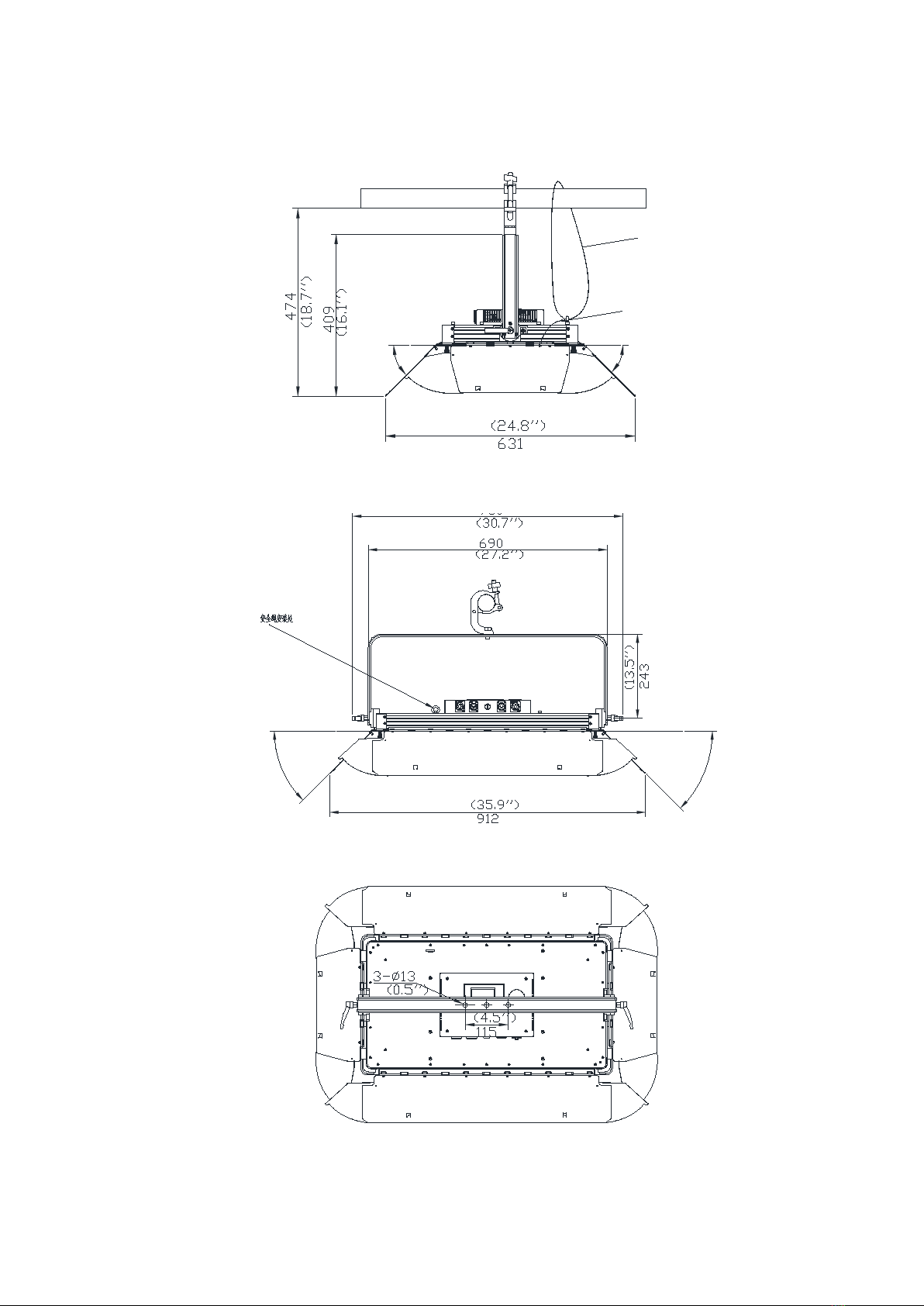
2.1 Dimensions..............................................................................................................................................................3
2.2 Accessories..............................................................................................................................................................3
3. Packing and shipping..................................................................................................................................................4
3.1 Unpacking ...............................................................................................................................................................4
3.3 Packing after use .....................................................................................................................................................4
4. Installation...................................................................................................................................................................4
4.1 Clamps installation..................................................................................................................................................4
4.2 Device installation...................................................................................................................................................5
5. Power / Control connection ......................................................................................................................................5
5.1 Power connection....................................................................................................................................................5
5.2 Control connection..................................................................................................................................................5
5.3 Testing.....................................................................................................................................................................6
6. Control panel...............................................................................................................................................................6
6.1 Panel instruction......................................................................................................................................................6
7. Technical specification................................................................................................................................................7
8. Menu structure............................................................................................................................................................9
9. DMX protocol............................................................................................................................................................10
10. System wiring diagram...........................................................................................................................................11
12. Maintenance and Troubleshooting........................................................................................................................12
12.1 Cleaning and maintenance...................................................................................................................................12
12.2 Troubleshooting...................................................................................................................................................13
13. Spare parts list.........................................................................................................................................................15

1
1.Safety instructions
Before using the fixture, read the latest version of the product user manual, paying particular attention to
the safety instructions. Please check www.gtd-lighting.com for the latest revision/update of the user manual.
Indoors use only.
m
ta
tc
The manufacture of this fixture, are not responsible for damages, resulting from misuse of this
fixture, due to the disregard of the information printed in this user manual.
DANGER!
Hazardous voltage. Risk of lethal or severe electric shock
WARNING!
Wear protective eyewear. Never look directly into the light source.
WARNING!
Burn hazard. Hot surface. Do not touch.
Only to direct mounting on non-combustible surfaces.
Minimum distance to lighted objects.
Replace all cracked glass shields.
Maximum ambient temperature.
Maximum temp of the external surface.

2
General guidelines
The protection rating of this product IP20.
Never open this fixture while it is in use.
The fixture should be kept clean. DO NOT operate the fixture in extreme heat or dusty environments. Avoid contact
with chemical liquid.
Minimum distance to lighted objects must be 16.4 feet (5m).
Maximum temp of the external surface 167˚F (75˚C).
Maximum ambient temperature 113˚F (45˚C).
Minimum distance of inflammable materials from the surface 1.6 feet (0.5m).
Lamp should be replaced if damaged or distorted in shape due to extreme heat.
Cover, prism or LCD Menu Function Display with visible damages such as cracks or scratches must be replaced to
ensure performance of the fixture.
Disconnect the fixture from power before changing any parts or accessories.
Basic insulation should be maintained between the controllable device and the product power supply.
Make sure that the installation area can hold a minimum point load of 10 times the weight of all installed fixtures,
clamps, cables, auxiliary equipment, etc. Make sure that the cover, clamps and locks are undamaged. Certified safety
cables must always be used when installing the fixture.
The fixture is only intended for installation, operation and maintenance by qualified professional. Instructions stated in
the manual must be complied.
The fixture must be kept in a well-ventilated place at least 50 cm away from any wall surface. Check if the fans or
ventilation openings are unblocked.
This fixture uses discharge lamp. Avoiding reduce the lamp’s life, wait at least 15 minutes after powering off to allow
the unit to cool down before handling.
To ensure operational safety, broken or damaged cables and light source can only be fixed or replaced by certified
technicians, certified local distributors or the manufacturer.
Do not stick filters or other materials onto the lens. Do not modify the fixture or install other than GTD manufactured
parts.
For questions regarding safety operation, please contact our technical personnel or call the service hotline
+862061808296.

3
2. Production instructions
2.1 Dimensions
45°(min) 45°(min)
45°(min)
45°(min)
Safe rope
Safe rope

4
2.3 Accessories
Item Qty Unit Remark
User Manual 1 Pc --
Clamps 1 Set 117*80*24 ¢50*10KG
Safety cable 1 Pc φ3*80cm&φ1*15cm with hook Material:Steel
3-pins signal line 1 Set 1.5m*2.5mm² connect blue plug
3. Packing and shipping
3.1 Unpacking
Notes
All products are quality controlled before they dispatched to customers. If the fixture is damaged during delivery,
the customer must notify the shipper and manufacturer to file a damage insurance claim. Photographic evidence
of the damage must be provided.
Cardboard box(specification:840*485*185 mm)
:Open the box and take out the whole set of packaging foam
which are contained both the fixture and its accessories. Remove the foam from the top, put away the
accessories, and then take out the fixture wrapped in the plastic bag.
3.2 Packing after use
1. Switch off the fixture and wait for at least 5 minutes before disconnecting it from AC power. Cool down the
fixture for at least 15 minutes before packing.
2. Flight case: Wrap the fixture in plastic bags. Gripping the handle and then place it in the flight case along with
all the accessories carefully. Close the cover lid. The wrap page are not allowed over 3 layers. Do not upside
down.
3. Cardboard box: Wrap the fixture in plastic bags. Put it in the packaging foam along with all the accessories.
Place the other set of packaging foam on top then put it carefully in the cardboard box.
4. Installation
4.1 Clamps installation
The fixture can be placed on the stage or mounted on the truss which faces any direction. Attach the clamps to
the mounting position on the base of the fixture.
Warning:
Use two clamps when mounting the fixture. Turn the screws attached to each clamp a 1/4 turn clockwise
to lock. Always remember to use the safety cable which goes through the mounting hole on the base. Do not attach
the safety cable on the handle.

5
4.2 Device installation
1. Make sure there is no damage on the clamps or safety cables before installation.
2. The clamp is mounted on the chassis of the fixture. Horizontally insert the clamp into the mounting holes of the
chassis. Fasten the clamp tightly by a 1/4 turn clockwise. Fix another clamp in the same way.
3. Check if pan is locked before connecting the unit to AC power.
5. Power/ Control connection
5.1 Power connection
Connection method:
L (Live) Brown wire
E (Earth) Yellow / Green bi-color wire
N (Neutral) Blue wire
The voltage and frequency of the power source must be in compliance with the ones marked on the fixture.
It is strongly recommended that each fixture are to be connected to the power source separately so that they
can be switched on / off individually.
5.2 Control connection
The fixture has 3-pin XLR connectors for DMX data input and output as shown below. Connection between the
console and fixture, and between fixtures must be made with 2 core screened DMX signal cable. Maximum
connecting distance of signal cable is 150 meters. Additional DMX512 signal-amplifier is recommended for
longer distance.

6
Connect the Console’s DMX OUTPUT to the first fixture’s DMX INPUT, then the first fixture’s DMX OUTPUT to
the second fixture’s DMX INPUT and so on. It is recommended not to connect more than 32 units on a single
DMX universe. On the last fixture’s output connect a DMX terminator. (The terminator is a 3-pin XLR connector
with a 1/2W and 120Ω resistor between the pin 2 and pin 3) as shown below:
5.3 Testing
Connect the fixture to AC power. Check if the lamp is on and the fixture is independently controllable before
putting into operation.
6. Control panel
6.1 Panel instruction
The control panel features touch-sensitive buttons and LCD digital display for quick and easy setup of address
code and functions menu.
Switch the button can select the function menu.
Input Output
DMX terminator
Input Output
Console

7
7. Technical specification
Optical
Light source: LED 0.5W
Expected average lifetime: 50000 h
Color temperature correction: 2800K~6000K
Lumens:13000lm
Beam:110°(10%)、70°(50%)
CRI:97
Electrical
Power input, nominal: AC 100-240V 50/60Hz
Max. Power consumption: 230W
Max current:2.3A, PF: 0.94
Power supply unit: wide range electronic SMPS
Main fuse: 6.5A
Power input: Self-contained power cord
DMX data input/output: Chassis 3-pin
Control and programming
Control channels (DMX): 11/15
Protocol: DMX-512 RDM
Display: Nixie tube
Physical / Installation
Weight: 9 Kg (19.8 lbs.)
IP rating: IP20
Material: Aluminum, steel, plastic
Mounting points: fixed folding lamp hook + attachment points for safety wire
Dynamic effects
Pan/Tilt movement: 540˚/270˚,adopting a function which resets 32bit accurately and automatically
Strobe: 1-25Hz, strobe randomly, pulse randomly, strobe synchronously and asynchronously
Dimmer: 0-100%, electronic linear dimming
Thermal
Operating range: 14˚F - 113˚F ( -10˚C - 45˚C)
Startup range: -13˚F - 113˚F( -25˚C - 45˚C)
Storage range: -40˚F - 140˚F( -40˚C - 60˚C)
Cooling: Active fan
Humidity: ≤85%

8
Certification and Safety
EMC: EN 55103-1:2009, EN 55103-2:2009, EN 61000-3-2:2006+A2:2009, EN 61000-3-3:2013,
GB/T 17743-2007, GB 17625.1-2012
Safety: EN 60598-2-17:1989/A2:1991, GB 7000.1-2015, GB 7000.217-2008
Photometric
Other features
Enhanced stability of the fixture due to the wide input voltage AC/DC switching power supply which both
reduces the impact of power and voltage fluctuations, and removes the restriction of voltage and frequency
variations in different countries.
Automatic energy saving: when the shutter or CMY is closed, power consumption will be reduced automatically
with the photoelectric tracking induction technology.
Sleep mode: uses the most advanced technology to activate sleep mode remotely. When the fixture is
disconnected from signal, the sleep mode is enabled automatically to make it more stable and safer. Sleep
time can be customized.
Power setting: built-in continuous rechargeable battery, allowing setting functional data via LCD interface
without power connection.
Communications Design:DMX wired/wireless transmission, bidirectional-control technology,upgrade the
software quickly and conveniently by using DMX cable.
Thermal design: The wind drainage and intelligent temperature monitoring technology can monitor lighting’s
state : on /off. It can adjust the thermal design by the position’s temperature of lighting so that the temperature
can be controlled.
∅
70°
70° 110°
25m
20m
15m
10m
5m
0
5m
10m
15m
20m
25m
5341180 289 153
0 2
2.8 ∅5.6 ∅8.4 ∅11.2
∅5.6 ∅11.2 ∅16.8 ∅22.4
4 6 10
70°beam distance(50%)
110° 5341180 289 153
110°beam distance(10%)
illuminance(LUX)
Distance(m)

9
8. Menu structure
Level 1 Level 2 Level 3 Level 4 Info
Run setting Address:001~
XXX
Setting the DMX address
Device Info
Time Info Since power on
Total Time
Return
XXXXXX Hour
XXXXXX Hour Since power on time
Product total run time
Temperature
XXX ’C/’F
Body temperature
Software Version
X.X
The software version
Return
Return to the previous menu
System Setting Status Setting No Signal Status
Standby Time
Return
Off/Hold/Auto
Disable/1~120Min,30 The status while no signal
Standby time
Return
Fan Speed Smart Control
High Speed
Low Speed
Auto fans speed
Fans high speed
Fans low speed
Display Setting Backlight Time
Key Lock
Lightness
Language
Screen auto
Return
1~80 Min/Disable
Enable/Disable
15~100% 80%
Chinese/English
off/on/auto
Backlight off time
Press <menu> 3s to unlock
Back lightness of screen
Change the language
Screen change Setting
Return to the previous menu
Temperature Unit Celsius
Fahrenheit
Temperature unit
Value Default Dimmer
Color Temp
Color Temp F
Return
Dimmer =XXX
Color Temp =XXX
Color Temp F =XXX
The default value
Restore Default Yes/No Restore to default value
Select Device - Password-
XXX(99)
GTD LP200
GTD LP200A
GTD LP200 B
……
Select the model of the
device
Channel
Adjust Dimmer
Color Temp
Color Temp F
Return
Dimmer =XXX
Color Temp =XXX
Color Temp F =XXX
Manual control
Retrun Return to the previous menu
*Settings hightlighted in light grey are default value

10
10. DMX Protocol
DMX mode
Name DMX value DMX percentage Function Default
DMX Value
Standard
(3ch)
1 Intensity 0 255 0.0% 100.0% No light→Full light 0(0%)
2 Color
Temperature
0 15 0.0% 5.9% 2800K
0(0%)
16 30 6.3% 11.8% 3000K
31 45 12.2% 17.6% 3200K
46 60 18.0% 23.5% 3400K
61 75 23.9% 29.4% 3600K
76 90 29.8% 35.3% 3800K
91 105 35.7% 41.2% 4000K
106 120 41.6% 47.1% 4200K
121 135 47.5% 52.9% 4400K
136 150 53.3% 58.8% 4600K
151 165 59.2% 64.7% 4800K
166 180 65.1% 70.6% 5000K
181 195 71.0% 76.5% 5200K
196 210 76.9% 82.4% 5400K
211 225 82.7% 88.2% 5600K
226 240 88.6% 94.1% 5800K
241 255 94.5% 100.0% 5900K
3 0 65535 0.0% 100.0% Color temperature fade,
fine(LSB)

11
11. System wiring diagram
GND
+37V
SCR0115A
JF1
JF2
GND
+28V
JBA JBA
U201P10
Pan Motor Tilt Motor
Base Fan*1
+28V
+37V
GND
LAMP
M.PAN M.TIL
P.PAN
P.TIL
PAN Magnetic Sensor
TIL Magnetic Sensor
U101Q10
JE1 JE2
J1
SDI0112B
(
Display key board
SDI0803F)
Power line 1.5mm2
FG
L
N
Switch
LED
LCR0117B
Fuse
EDS565-3728P
Switching
power supply
+37V
GND
J9
JE1
JE2
JBA
SLS0802C
SLS0802C
GND
+28V
JE1 JE2 JE3 JE4 JE5
F1 P1
F2 P2
F3 P3
F4 P4
F5 P5
SCB0600B
GND
P1
J8
CTO
JE1 LED
Led Fan*4
JB1 JB2 J B3 JB4
JB1
L
N
GE
L
N
GE
POWER
IN
POWER
OUT
M_1 M_2 M_3 M_4
M_5
M_6
M_7
M_8
JK1 JK2 JK3 JK4
JK5JK6
JK7
JK8
JE1
JE2
P1
JB1
JB2
JB3
CMY
C
Magnetic
Sensor
SCR0112B
U401P10
CMY,color,gobo drive board
M
Magnetic
Sensor
Y
Magnetic
Sensor
CTO
Magnetic
Sensor
Fixed
Gobo
(Wheel)
Magnetic
Sensor
Fixed
Gobo
(Wheel)
Color
Magnetic
Sensor
Color
(Wheel)
Gobo
Magnetic
Sensor
Gobo
Gobo.
ROT
Magnetic
Sensor
Gobo.
ROT
M_1 M_2 M_3
M_4
M_5
M_6
JK1 JK2 JK3
JK4
JK5
JK6
JE1
JE2
P1
JB1
JB2
JB3
SCR0113B
Focus drive board
Zoom Zoom
Magnetic
Sensor
Focus Focus
Magnetic
Sensor
Focus
2
Prism
Magnetic
Sensor
Prism.
ROT
Magnetic
Sensor
Prism
Prism.
ROT
Frost
XLR
socket
X&Y drive board
LED drive board
Display board
Fan*1
U501P10
U301N10

12
12. Maintenance and Troubleshooting
12.1 Cleaning and maintenance
It is required that the fixture should be kept clean and well maintained to ensure its reliability. Its lifespan mainly depends on
the working environment and proper operation. Should you have any questions, please consult a technical engineer of GTD
Lighting.
Notes: Damage resulted from dust, smoke, oil or improper use is not covered by warranty.
Notes: Disconnect the fixture from AC power, and let it cool down for at least 15 minutes before opening the housing.
Make sure to use a soft cloth to clean the optical components, and be careful, as the coating is easily scratched. Do not use
any organic solvent such as alcohol to clean the reflector mirror, dichroic color filters or housing of the fixture.
If the lens is cracked or otherwise damaged, replace it immediately.
If the lamp becomes damaged or deformed in any way it must be replaced.
If the light from the lamp appears dim, this normally indicates that it is reaching the end of its life span and should be
changed at once. Aged lamps run to the extremity of their life might explode.。
If fixture does not function, check the fuse on the power socket of the fixture. Replace the fuse of the same specification
if it is blown.
The fixture isequipped with thermal-protection device that will switch off the lamp in case of overheating. If this happens,
please check that the fans are not blocked, and clean them if they are dirty. Check whether the fans are operational. If
not, call a qualified technician.
12.2 Troubleshooting
Problem Possible Cause Suggested Correction
No response after
connected to A/C
power
Power switch not turned on. Turn on power switch.
Take out the fuse and check if it is blown. Locate the blown fuse. Remove the broken fuse.
Insert areplacement fuse of the correct amperage
Abnormal A/C input (A/C power socket,
power cables, luminaire power socket).
Replace AC power socket and power cables,
and then adjust power socket for proper
connection.
No DC voltage from switching power supply.
Check if the switching power supply has DC
voltage output. Replace the switching power
supply.
No response or
wrong response to
the commands of
the control system
DMX cables disconnected from fixture’s
DATA IN connector.
Connect DMX cable to the fixture’s DATA IN
connector.
Open circuit or short circuit fault in the DMX
cables. Replace DMX cables as required.
Wrong DMX address for the fixture in the
control system.
Ensure the address in “Run setting > Address
Setting >Address” of the fixture is consistent
with the address in the control system.

13
Problem Possible Cause Suggested Correction
Misuse in “Channel setting > Channel Mode
of the fixture.
Choose the channel mode in “Channel setting >
Channel Mode” of the fixture as required by the
user
Malfunctioning of DMX cannon input/output
connectors. No input/output voltage to the
main control board of the fixture.
Troubleshooting the DMX XLR signal plate of
the fixture,replace the main control board of the
fixture.
The lamp does not
start when switch
is turned on
Normal end of lamp life.
Test the lamp in an adjacent fixture which is
known to be operating properly and then replace
as necessary
Whether the function of the relay board is
intact, whether the signal is normal or not. Repair or replace.
Shorted leads between ballast and the lamp Replace components as required.
Incorrect ballast output.
Check ballast output to determine if it conforms
to lamp requirements. If voltage and current do
not stabilize in five to ten minutes warm-up
time, ballast output is incorrect and adjustment
should be made. Check capacitor wiring, if
visibly available, to determine if capacitors are
properly
wired.
Incorrect triggers output. Replace triggers.
The lamp is off
unexpected
The fixture is in sleep mode
Should the fixture is not in active use for
“standby time”, the sleep mode is enabled
automatically to make it more stable and safer,
sleep time can be customized.
Lamp has been operating: cool down time
insufficient.
Environmental conditions such as extreme
temperatures will have the fixture stop working,
the lamps will require a period of time to cool
and re-establish optimum starting conditions.
Restart time varies with the degree of
ventilation built into it, ambient temperature,
and draft conditions.
Overheat ballast resulting in premature failure
or damaged ballast.
The ballast incorporate internal automatic-
resetting thermal protection, which deactivates
the ballast should it overheat. Normal operation
resumes once the ballast has cooled sufficiently.
Burned-out or failing lamps, or high
temperatures in or around the fixture, can cause

14
Problem Possible Cause Suggested Correction
the ballast to overheat, so we need solve the
problem and replace components as required
Thermostat damaged. Replace.
Shaking, wrong
position, and out
of control gobo
wheel
No function the connector between gobo
wheel motor and drive, loose, damaged, or
broken cables connecting the gobo wheel
and drive.
Reconnect the gobo wheel motor to the drive, and
replace cables as required.
The gobo wheel motor's drive IC on the PCB
might be out of condition.
Replace the drive having the same software
version as required.
Dislocated magnetic tube and positioning
magnet, or damaged magnetic tube.
Calibrate the position of the magnetic tube to
the positioning magnet, and replace magnetic
tube as required
Shaking motor, wrong rotation angle, losing
step or damaged motor Replace the motor as required.
Decreased
brightness, uneven
pattern projections
Normal end of lamp life.
Test the lamp in an adjacent fixture which is
known to be operating properly and then replace
as necessary
The midline of the lamp is not aligned with
the center point of the effect assembly
(consisting of the rotating gobo wheel, static
gobo wheel, color wheel, strobe, prism, and
frost), focus module, and object lens.
Reinstall the lamp. Adjust the lamp position
until the midline of the lamp is aligned with the
center point of the effect assemblies (consisting
of the rotating gobo wheel, static gobo wheel,
color wheel, strobe, prism, frost, the focus
adjusting module, and the object lens).
Excessive dusts or smudges on the effect
assembly, focus module and objective lens.
Follow the instructions stated in this user manual
to clean the effect assembly, focus module and
objective lens.
Damaged or deformed effect assembly,
focus module or objective lens. Replace the damaged or deformed components
Wrong color
Normal end of lamp life
Test the lamp in an adjacent fixture which is
known to be operating properly and then replace
as necessary
Excessive dusts or smudges on the rotating
gobo wheel or color wheel.
Follow the instructions stated in this user manual
to clean the rotating gobo wheel or color wheel.
Rotating gobo wheel, color wheel with
coating wearing off, damages or deformation
Replace the worn-off, damaged or deformed
rotating gobo wheel and color wheel

15
Problem Possible Cause Suggested Correction
Non-clear shape
Excessive dusts or smudges on the rotating
gobo wheel or color wheel
Follow the instructions stated in this user
manual to clean the rotating gobo wheel or color
wheel.
Excessive dusts or smudges on the focus
module or objective lens
Follow the instructions stated in this user
manual to clean the focus module or objective
lens
Damaged or deformed focus module or
objective lens.
Replace the damaged or deformed focus module
or objective lens.
13. Spare parts list
Name P/N Qty Notes
display panel 5802020078A 1 SDI3002C 4 1 without 451MCU
Al-Substrate 5802010071A 6 LJB3002B 6 1
LED drive board 5802030127A 1 LED 3004B-1 6 1

16
Guangzhou GTD Culture & Technology Group Co., Ltd.
Tel:86-20-61808296
Fax:86-20-61812282
http://www.gtd-lighting.com
Table of contents
Other GTD Lighting Equipment manuals

GTD
GTD GTD-371C II BSW User manual

GTD
GTD GTD-L372P User manual

GTD
GTD GTD-L336P User manual

GTD
GTD GTD-F3 II BSW User manual

GTD
GTD GTD-F4019 WASH User manual

GTD
GTD GTD-LM660 II Profile User manual

GTD
GTD GTD-330 N BSW User manual

GTD
GTD GTD-F10 II PROFILE User manual

GTD
GTD 440P II BSW User manual

GTD
GTD LM1000 N BSWP User manual