A.B.S. Flexilo FLAT BOTTOM User manual

Assembly-, Operating-, and Filling Instructions
Flexilo FLAT BOTTOM for wood pellets
Construction: Plug-In System galvanized
Information on the manual:
The present assembly manual contains important information on safe and appropriate
assembly of the A.B.S. Flexilo FLAT BOTTOM for the storage of wood pellets.
The assembly manual is intended for skilled mechanics, which have,
based on expert training, the respective knowledge
and experience. As we are interested in continuously
improving our technical documentation, we would be
pleased to get suggestions for improvement.
The manual has to stay with the heating system or
the silo. Please make sure that the manual is at
any time on-hand if required.
A.B.S. Silo- und
Förderanlagen GmbH
Industriepark 100
74706 Osterburken - Germany
Tel. +49 62 91/ 64 22-0
Fax +49 62 91/ 64 22-50
www.abs-silos.de

Operating and Assembly Instructions Flexilo FLAT BOTTOM for wood pellets
Table of contents
Subject to technical change Issue 09/2016 Page 2 of 32
©A.B.S. Silo- und Förderanlagen GmbH
Table of contents:
1 Note ............................................................................................................................... 3
1.1 Symbols used.......................................................................................................... 3
1.2 Normative references.............................................................................................. 3
1.3 Pellet quality, Intended use ..................................................................................... 3
1.4 Approvals and Compatibility to Pellet Boilers........................................................... 4
1.5 Warranty and Guarantee......................................................................................... 4
2 Safety Information.......................................................................................................... 6
2.1 General safety information ...................................................................................... 6
2.2 Fire prevention........................................................................................................ 7
2.3 Earthing................................................................................................................... 7
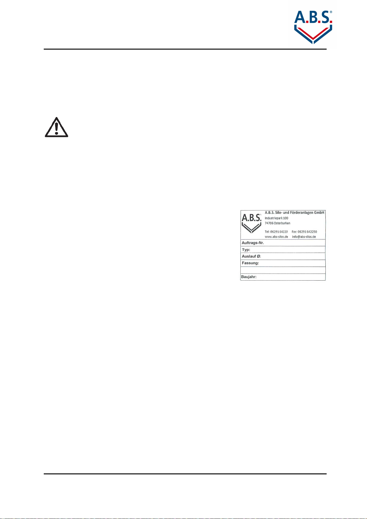
2.4 Nameplate............................................................................................................... 7
2.5 Maintenance............................................................................................................ 7
2.6 Storage Aeration..................................................................................................... 8
3 Room Layout.................................................................................................................. 9
3.1 Room size............................................................................................................... 9
3.1.1 Distance from walls.............................................................................................. 9
3.1.2 Distance from ceiling ........................................................................................... 9
3.2 Condition of the room.............................................................................................10
3.3 Room fixtures.........................................................................................................10
3.4 Room deaeration....................................................................................................11
3.5 Size / Storage Volume............................................................................................11
4 Scope of delivery...........................................................................................................12
4.1 Scope of delivery (standard)...................................................................................12
4.2 Optional Accessories..............................................................................................16
5 Assembly.......................................................................................................................17
5.1 Pre-Assembly of the drawing irons.........................................................................17
5.2 Assembling the frame and struts............................................................................17
5.3 Assembling the silo bag to the top bars..................................................................19
5.4 Attaching the silo cover to the ceiling .....................................................................21
5.5 Fastening...............................................................................................................22
5.6 Mounting of Filling-set(s)........................................................................................22
5.7 Installing the suction probes...................................................................................23
5.8 Connecting the suction probes...............................................................................24
5.9 Hand outlet points – ascending screw conveyor access.........................................25
5.10 Installation opening ................................................................................................25
6 Final inspection.............................................................................................................26
7 Extract from accident prevention regulations.................................................................27
8 Filling instructions..........................................................................................................28
8.1 General instructions ...............................................................................................28
8.2 Filling nozzle(s)......................................................................................................29
8.3 Filling with two filling nozzles..................................................................................29
8.4 Filling techniques ...................................................................................................31
8.5 Filling......................................................................................................................31

Operating and Assembly Instructions Flexilo FLAT BOTTOM for wood pellets
General Information
Subject to technical change Issue 09/2016 Page 3 of 32
©A.B.S. Silo- und Förderanlagen GmbH
1 Note
Please read these Instructions prior to assembling the Flexilo FLAT BOTTOM for wood
pellets.
1.1
Symbols used
Danger! This symbol identifies a hazard that could cause serious bodily injury or
even death if appropriate precautionary measures are not taken.
Caution: Risk of injury or damage to equipment!
Dangerous situations that can cause minor to serious bodily injury or damage to
equipment and property.
Risk of electric shock! Failure to observe the warning can endanger life and
limb through contact with electricity.
References and tips
1.2
Normative references
•ÖNORM M 7137: Wood pellets - Requirements for storage of pellets at the ultimate
consumer
•EN 303-5: Heating boilers for solid fuels
•EN14961-2: Wood pellets for non-industrial use
•ENplus – Handbook for the certification of wood pellets for heating use, version 2.0
•Sample fire ordinance 2005
•VDI guideline 3464 (green print 2012): storage of wood pellets by ultimate consumer
1.3
Pellet quality, Intended use
The Flexilo FLAT BOTTOM for wood pellets is intended solely for the storage of wood
pellets. The maximum acceptable bulk good temperature is 50 °C.
If you want to store other materials you need to get in touch with the manufacturer
necessarily.
We assume use of quality pellets complying with EU-Norm EN 14961-2
respectively
complying with DINplus that have a diameter of 6 mm. According to the DEPV-guidelines
only certified ENplus A1 quality pellets are recommended.
Quality class A2 is used in larger boilers in excess of 100 kW like in the commercial area.
The quality classes are distinguished primarily by the ash content and the permissible ash
softening temperature. The boiler manufacturer must permit the use of the A2 quality pellets
in their boilers.

Operating and Assembly Instructions Flexilo FLAT BOTTOM for wood pellets
General Information
Subject to technical change Issue 09/2016 Page 4 of 32
©A.B.S. Silo- und Förderanlagen GmbH
Important criteria of wood pellets according to the ISO 17225-2 from 2014:
Quality A1
Quality A2
diameter (mm) 6 or 8
length(mm) 3,15 to 40
moisture content (% by mass) <=10
ash content (% by mass) <=0,7
<=1,2
mechanical strength (% by mass)
>=97,5
finest content (% by mass) <=1
overlength (40 – 45 mm) <=1
heating value (kWh/kg) 4,6 to
5,3
bulk density (kg/m³) >=600
600 – 700
nitrogen content (% by mass) <=0,3
<=0,5
sulphur content (% by mass) <=0,04
<=0,05
chlorine content (% by mass) <=0,02
ash fusion temperature* (C°) >=1200
>=1100
* This value is only mandatory for ENplus certified pellets. It refers to the temperature at
which the wood ash deforms and thus can lead to scorification in the combustion chamber.
Poor quality pellets can impair operation of your heating system and have an adverse effect
on the storage and conveying equipment. Only high-grade pellets can assure reliable and
problem-free operation of the pellet-fired boiler and the conveying systems. If necessary,
have the supplier confirm the quality of the pellets.
ENplus certificate
ENplus certified pellets are available for quality classes A1
and A2. Manufacturers and suppliers of high quality wood
pellets and further information can be found under
www.enplus-pellets.de.
1.4
Approvals and Compatibility to Pellet Boilers
There are approvals of various boiler manufacturers for the A.B.S. Flexilo FLAT BOTTOM.
Through individual solutions of extraction devices and conveying systems in special cases
connections to the silo can be created.
1.5
Warranty and Guarantee
Please comply with your country-specific standards and directives regarding
assembly and operation of the silo! Observe the information contained in these
instructions! It is binding and must be observed.

Operating and Assembly Instructions Flexilo FLAT BOTTOM for wood pellets
General Information
Subject to technical change Issue 09/2016 Page 5 of 32
©A.B.S. Silo- und Förderanlagen GmbH
The "General Terms and Conditions of Business of A.B.S.” apply in all cases. These are
available to the operator no later than upon conclusion of the sales agreement. Warranty and
liability claims associated with personal injury or property damage are excluded if they can
be attributed to any one or several of the following causes.
−Unintended and improper use of the equipment.
−Operation of the equipment when safety devices are defective, not properly attached or
when safety devices and guarding are not functioning properly.
−Failure to observe the information contained in the Operating Instructions with regard to
storage, transportation, assembly, start-up, operation, and maintenance.
−Unauthorized structural changes.
−Improperly performed repairs.
−Catastrophic incidents resulting from the action of a foreign object or force majeure.
−Use of not yet released additive pellets (PowerPlus, pelprotec ®, etc.). Please contact us
for information on the current supply level.
−In case of white rust.
White rust can occur during transport, for example. Protect frame against water, water spray
is already enough to form white rust.
However, if this cannot be avoided, then the white rust can quite easily be removed with
RZ51 zinc cleaner.
The manufacturer’s warranty and guarantee are based on the assumption that the silo
system has been properly assembled and commissioned by qualified personnel.
Deficiencies and damage arising from improper assembly, start-up and operation are
excluded from any and all warranty and guarantee coverage.
To ensure operation of the system as intended, the manufacturer’s instructions must be
followed. In particular, the equipment must be operated with the pellets stipulated in Chapter
1.3.
Damage to the silo from rodents or attributable to other external forces is not covered by our
warranty.
Damage attributable to flying sparks caused by cutting and welding work is excluded from
warranty coverage.
The guarantee covers only the items supplied by us.
Only original replacement parts or parts expressly approved by the manufacture may be
installed in the system.

Operating and Assembly Instructions Flexilo FLAT BOTTOM for wood pellets
Safety Information
Subject to technical change Issue 09/2016 Page 6 of 32
©A.B.S. Silo- und Förderanlagen GmbH
2 Safety Information
Please observe the following safety information!
2.1
General safety information
Danger to life in the event of a dust explosion caused by electrostatic discharge
•The filling nozzle and frame of the silo must always be connected to the potential
equalization system of the building in order to prevent build-up of static electricity. If
several pipe segments are connected to one filling line, all of the connections must be
interconnected electrically to one another.
•The room where the silo is installed must not be hermetically sealed, since the
overpressure created during the filling process escapes into the storage room.
•An exhaust air opening of 200 cm² or rather according to VDI guideline 3464 in the
storage room is necessary. If necessary open a window during the filling process.
•Heating boilers and fuel supply systems need electricity to operate. Improper
installation can mean that life is endangered.
•When filling the silo with a tank truck, the boiler must always be switched off in time.
•Point out possible sources of danger to the customer. The currently valid fire
protection and VDI guidelines must be satisfied prior to start-up.
•In order to avoid hazards associated with improper handling of the system, have
installation, initial start-up and service performed only by suitably qualified personnel
in compliance with all applicable regulations and manufacturer's instructions.
•Use only metal piping with Ø DN 100 mm and a smooth inside edge for the extension
of the filling line (galvanized, without burrs or welding sputter; use of plastic pipes is
not allowed!).
•The filling-set and the filling hose of the tank truck should not be longer than 30 m.
•Keep the filling system within the building as short as possible in order to minimize the
physical load to which the pellets are subjected, thus keeping fines and powder
created by abrasion low. Avoid tight bends as much as possible!
•The fill coupling has to be accessible and unproblematicly reachable (without using
any ladders etc.) for the tank truck driver.
•Protect fabric silos from rodents
•Do not change any settings or make any modifications to the system; if these are
necessary, contact A.B.S. first to obtain approval.
•Knowledge of the operating instructions and maintenance procedures is a
prerequisite. Prior to start-up, please read these Operating Instructions carefully and
completely, and remember to observe the safety information in particular.

Operating and Assembly Instructions Flexilo FLAT BOTTOM for wood pellets
Safety Information
Subject to technical change Issue 09/2016 Page 7 of 32
©A.B.S. Silo- und Förderanlagen GmbH
2.2
Fire prevention
All fire prevention regulations must be satisfied prior to start-up. (subject to country-specific
modifications).
2.3
Earthing
Attention! Let the earthing of your pellet storage area be executed by a
specialized company.
•All conductive parts of the silo must be grounded expertly.
•In particular the removal system, the steel frame and the connecting armature have to be
earthed.
•The filling lines must also be connected conductive and grounded professionally with a
cable (4 mm ²) to the potential equalization conductor (by a qualified electrician for
example).
•Especially the earthing parts have to be connected to the potential equalization and/or the
main potential equalization with specific PA conductors.
2.4
Nameplate
The nameplate stating the calculated storage capacity must
be attached to the pellet silo at a readily visible location, e.g.
at the filling nozzle or on one of the frame’s legs. The
nameplate is included in the shipping documents that
accompany Flexilo FLAT BOTTOM for wood pellets when it is
delivered.
Nameplate with calculated storage capacity
2.5
Maintenance
Regular cleaning of the bearing is required to ensure continuous, trouble-free and safe
heating operation. The fines content and the wood dust should be removed.
When cleaning, please note the following:
•Enter storage areas only when in compliance with safety regulations: Switch off
heating and discharge system, adequately ventilate before entering.
•Clean the removal system prior to new filling of dust and debris. Wear dust mask of
filter class P2.
•Heat silo sack empty regularly and clean the silo sack through movement from dust
while the removal system is uninstalled.
Vacuum the storage out. In private storage, the cleaning can be done with
commercial vacuum cleaners with HEPA filters. The vacuum cleaner should not work
at the highest level to avoid overheating and to prevent ignition hazards.
•
For reasons of occupational health and safety, an industrial vacuum cleaner with filter
class M is required for cleaning pellet storages. Earth buried storage and all other
storages starting at a capacity of 40 tons may only be accessed with a CO warning
device.
•Until the next filling process please fill the silo manually with pellets in sacks (through
the manual filling nozzle).

Operating and Assembly Instructions Flexilo FLAT BOTTOM for wood pellets
Safety Information
Subject to technical change Issue 09/2016 Page 8 of 32
©A.B.S. Silo- und Förderanlagen GmbH
•Please check if the silo has damages caused by rodents or other external influences.
•The bolting of the steel frame should be checked as well.
•Please check the fastenings of the Filling and removal systems.
•Make sure that all other openings on the silo are closed.
After two to three deliveries
-
at least every two year
s
-
the time before the
next pellet delivery should be used to clean the storage.
Please observe the recommendations concerning the maintenance of the boiler
manufacturers.
2.6
Storage Aeration
Wood pellets are a fuel that is environmentally safe and from which no health risk arises, if
handled properly. Wood pellets can develop an odour depending on the type of wood used.
The reason for this lies in the extractive, the wood's own oils, fats and resins, which are
activated during the pressing process and slowly outgas in the following weeks or
decompose when in contact with the air. Compared to other wood products wood pellets
have a very large surface area and are heavily used in their cell structure by the pressing
process. The result is that the release of the volatile components is faster, especially in fresh
pellets and at high ambient temperatures. Emissions usually decrease after a few weeks and
the odour associated evaporates completely.
The emissions of wood pellets consist of volatile organic compounds (VOCs), carbon
monoxide (CO) and carbon dioxide (CO2). Among the VOCs are, for example, the so-called
terrene that in rare cases occur and are responsible for a "chemical" odour (such as
turpentine). Other ingredients such as aldehydes and carbon monoxide can produce an
unhealthy effect and therefore should not enter into the living area. To avoid any risk, two
simple principles must be observed.
•The storage room, or the room where the final storage is set up, must be sealed off from
the living area.
•The storage room ventilation (> 200 cm ²) should be directly above the openings to the
outside or, if this is not possible, through openings in to a well-ventilated room.
Elaborate ventilation solutions are required for larger storages (> 10 t) and vent lines > 5 m.
These are described in detail in the VDI guideline 3464 "Storage of wood pellets at the end
user ".
Each pellet storage room or set up room for final storage must be ventilated.
The ventilation openings should be designed in a manner that they do not
end directly under windows or air intakes.

Operating and Assembly Instructions Flexilo FLAT BOTTOM for wood pellets
Room Layout
Subject to technical change Issue 09/2016 Page 9 of 32
©A.B.S. Silo- und Förderanlagen GmbH
3 Room Layout
Please observe the following planning steps; only in this way can
problem-free operation be assured.
Failure to comply can result in damage to the equipment and system
malfunctions or put individuals and equipment at risk.
Planning the room layout is a prerequisite and requirement for setting up the A.B.S. Flexilo
FLAT BOTTOM for wood pellets. The plans for the rooms must have already been given
some thought when ordering the silo. Nevertheless, prior to installation, check the
dimensions and existing conditions (see the next chapter).
Compliance with local regulations and proper construction of the building are the
responsibility solely of the purchaser of the equipment and are prerequisites for coverage by
the warranty and guarantee.
3.1
Room size
The required silo size depends on the size of the room. Please check the dimensions of both
the silo and the room prior to installation. The dimensions of the silo frame are stated on the
delivery documents.
The dimensions of the silo frame can be determined by measuring the steel parts:
Length of the frame = Length of the long bars
Width of the frame = Length of the shorter bars
Height of the frame = Length of the frame feet (stands) + height of the top bar
The silo, the manual filling nozzle and the removal units must be easily accessible
for maintenance.
3.1.1 Distance from walls
A distance of 10 to 15 cm is required between the silo frame and walls in order to provide
ventilation at the back of the silo and protect against mechanical damage. Because of the
bulk nature of the pellets, the side walls of the silo may bulge slightly.
The side of the silo where the filling line is attached must have a clearance of at least
80 - 100 cm. If you fill from outside 30 cm are enough.
(Further instructions and examples for the installation can be found in our planning
documents).
3.1.2 Distance from ceiling
A minimum distance of 20 cm is required between the upper edge of the silo frame and the
ceiling to provide space for the filling line. To prevent damaging the top fabric of the silo
during filling, no sharp or sharp-edge objects should be fastened to the ceiling.

Operating and Assembly Instructions Flexilo FLAT BOTTOM for wood pellets
Room Layout
Subject to technical change Issue 09/2016 Page 10 of 32
©A.B.S. Silo- und Förderanlagen GmbH
3.2
Condition of the room
A stable supporting surface as the installation site is a prerequisite for setting up the silo. The
floor must be horizontal; if this is not the case, any unevenness must be corrected through
use of suitable underlay material (e.g.: steel plates). The load-bearing capacity of the floor
has to be checked according to the silo capacity.
For silos up to about 3.1 t, the plates at the bottom of the frame feet (stands) have
dimensions of 120x120 mm; starting at about 3.2 t, the dimensions are 140x140 mm. For
silos with a capacity of 8 t or higher, the load per frame feet (stand) can exceed 2,000 kg;
larger plates are available in such cases. Please consult the manufacturer directly with your
questions in this regard and check the permissible floor loading.
This only applies if the silo does not completely lie on the floor.
Load on the stands: tonnage x 1/6
Load on the floor: tonnage / base of the silo
The base connectors must be secured by means of anchor bolts.
Rooms with moisture levels normally found in cellars do not present any problems; however,
condensation must not occur. In case of humidity the room must be ventilated properly. The
silo fabric is air-permeable and may cause the wood pellets to absorb humidity at the silo
walls.
Make also sure that humidity does not enter the filling pipe if it is directed from outside into
the storage area.
When setting up outdoors, the following applies:
A properly levelled and stable concrete foundation must be available for anchoring the frame
feet (stands). The foundation can be designed as a slab with strip footing or as individual
foundations. The silos should be protected against moisture from below. For outdoor
installation, the frame feet (stands) should be galvanized. The silo must be protected from
direct sunlight and the effects of weather (e.g. place in a wood or metal enclosure or a
coating).
3.3
Room fixtures
Room fixtures such as drain pipes, ceiling hooks, water pipes, etc. must already be
considered in the planning phase, or be removed before installing the Flexilo FLAT BOTTOM
for wood pellets, if these interfere with the installation and proper operation of the silo.
There must be no sharp or sharp-edged objects near the silo bag. If it is not possible to
remove such objects, they must be covered.
There must be no lamps, lines of any kind, sharp, hot or damp contact surfaces above the
pellet silo.

Operating and Assembly Instructions Flexilo FLAT BOTTOM for wood pellets
Room Layout
Subject to technical change Issue 09/2016 Page 11 of 32
©A.B.S. Silo- und Förderanlagen GmbH
3.4
Room deaeration
The conveying air used to blow the pellets into the pellet silo must be allowed to escape
during filling by opening a window or door.
A cross-sectional area of at least 200 cm² or rather according to the VDI guideline 3464 is
necessary for this purpose. Windows, unused chimneys and openings in the masonry are
permissible for this purpose.
Caution required when venting lines > 5 m. Artificial ventilation necessary -
according to VDI guideline 3464 using a fan.
The conveying air escapes through the fabric on the top of the silo. Thus, no exhaust system
for the conveying air is needed when aerating the Flexilo FLAT BOTTOM.
Only on customer request the Flexilo FLAT BOTTOM
for wood pellets can be supplied with
a filling line and an exhaust air line in case of rooms without exhaust air or in specific cases.
But from the technical aspect this is not necessary and gives no advantage.
Please provide for a power connection for the suction blower when installing a suction line.
This can also be combined with an automatic shut-off function for the heating system.
In such a case, be sure to observe the separate filling instructions for A.B.S.
silos for wood pellets.
3.5
Size / Storage Volume
The storage area / the pellet storage should contain an annual need of pellets.
Thus the need for supply in winter at higher prices is avoided. At the same time requirements
are created to empty the storage and carry out cleaning work during the summer months.
Heat requirement in kWh/year 5000 10000 20000
Consumption of fuel oil in l/year 625 1250 2500
Pellet requirement in kg/year 1250 2500 5000

Operating and Assembly Instructions Flexilo FLAT BOTTOM for wood pellets
Scope of delivery
Subject to technical change Issue 09/2016 Page 12 of 32
©A.B.S. Silo- und Förderanlagen GmbH
4 Scope of delivery
The Flexilo FLAT BOTTOM for wood pellets consists of a steel
frame, which is shipped bundled on a pallet, and a silo bag,
which is packed in a carton together with accessories and
hardware required for assembly.
Delivery of the components
4.1
Scope of delivery (standard)
Pos.
Illustration
Description and
quantity
1
1 each Silo bag
of the appropriate size
packed in a plastic
bag
2
4 each Frame feet
3
4 each Supporting
bars
4
16 each drawing
irons - divided -
In the case of
rectangular silos, the
tension struts have
different lengths
(
8 x short and 8 x long)

Operating and Assembly Instructions Flexilo FLAT BOTTOM for wood pellets
Scope of delivery
Subject to technical change Issue 09/2016 Page 13 of 32
©A.B.S. Silo- und Förderanlagen GmbH
5
4 each Base connectors
6
4 each Top connectors
7 included:
32x 16x 48x
Screw sack with connecting
material for drawing irons
32 hexagon screws M12 x 30
16 hexagon nuts M12
48 washers U13
8 included: 16x
8x 8x
Screw sack with connecting
material for supporting bolt
8 screws M12 with shaft
16 washers U13
8 screw nuts M12 self locking
Supporting bolt screws after
support:
60x60 M12 x 90
80x60 M12 x 110
80x80 M12 x 110
120x80 M12 x 150
140x80 M12 x 170
10 resp.
1 - 2 pieces
Filling-pipe respectively filling-
injector
At a rack width of 2.20 m the Flexilo
®
is
delivered with a filling injector and from a
rack width of 2.50 m 2 filling pipes are
attached.

Operating and Assembly Instructions Flexilo FLAT BOTTOM for wood pellets
Scope of delivery
Subject to technical change Issue 09/2016 Page 14 of 32
©A.B.S. Silo- und Förderanlagen GmbH
11
1 piece per filling pipe
1 fastener 36/36
2 pipe clamps M10/M12
(pre-assembled on the fastener)
12 2x 2x 4x
Screw-set for filling-set
(pre-assembled on the fastener))
2 hex screws M12 x 25
2 spring washers Ø 12,2
4 washers Ø 13
13
1 piece per filling pipe
1 ground strap clamp NW 3/8-4“
14 2x
2x 4x
Screw-set for filling-set
(pre-assembled on the filling-pipe)
2 hex screws M10 x 140
4 washers M10
2 nuts M10
15
1 piece per filling pipe
Tension rings with sealing
compound
16
1 piece per filling pipe
Aluminium coupling with
temporary cover (Storz A)
17
1 piece per filling pipe
Hose clamp for ø 90 to ø 100 mm
18
OPTIONAL:
Support Structure for fixing the silo lid
½“ pipe must be provided by the customer

Operating and Assembly Instructions Flexilo FLAT BOTTOM for wood pellets
Scope of delivery
Subject to technical change Issue 09/2016 Page 15 of 32
©A.B.S. Silo- und Förderanlagen GmbH
19
1 x Assembly Instructions
1 x Filling Instructions
1 x Nameplate
(included in delivery note-bag)
Table listing items included in the shipment

Operating and Assembly Instructions Flexilo FLAT BOTTOM for wood pellets
Scope of delivery
Subject to technical change Issue 09/2016 Page 16 of 32
©A.B.S. Silo- und Förderanlagen GmbH
4.2
Optional Accessories
Depending on boiler-type different types of suction probes and manual switching units will be
installed.
Pos.
Illustration
Description
1
HP-SBH-5
manual switching unit (suction station)
Supplies: 1 x shift plank
4 x blind plank
2
HP-SS
A.B.S. suction probe
Ø 50/50
3
HP-SS-50/45
suction probe black
Ø 50/45
4
Hose clamps
Ø 40 – 60 mm
Optional accessories

Operating and Assembly Instructions Flexilo FLAT BOTTOM for wood pellets
Assembly
Subject to technical change Issue 09/2016 Page 17 of 32
©A.B.S. Silo- und Förderanlagen GmbH
5 Assembly
5.1
Pre-Assembly of the drawing irons
The drawing irons, flat material 25x5 mm, are divided in the galvanized plug-in system
version and must be fastened with screws M12 x 30 prior to assembly .
Please note that for rectangular silos, NOT for square silos, the scope of delivery contains 8
shorter and 8 longer drawing irons. These are assembled to 4 drawing irons for the long and
4 drawing irons for the shorter silo side.
Screwed connection of the divided drawing irons
CAUTION: Take care to bolt the drawing irons together in such a way that the bolts point
outwards to avoid them rubbing against the fabric.
5.2
Assembling the frame and struts
Do not start assembling the silo until you have become familiar with the situation at
the installation site and the room layout discussed in Section 3.
CAUTION! RISK OF INJURY!
Wear safety gloves during assembly of the steel frame as protection
against sharp edged metal components.
Pay attention to the room layout with regard to entry door and filling set.
Check the room height.
If filling is executed inside the room, please note that the minimum distance from
the wall to the frame has to be 80 - 100 cm, on the side where the silo will be filled.
Plug the plug-in elements into the frame stands and then connect the drawing irons
to the outer side. To connect the drawing irons with the stands and the plug-in
elements use screws M12x30.
With rectangular silos the drawing irons have a different length. The longer parts
must both be assembled on the two longer silo sides.
Protect yourself from frame feet which can tumble down and protect them while
assembling.

Operating and Assembly Instructions Flexilo FLAT BOTTOM for wood pellets
Assembly
Subject to technical change Issue 09/2016 Page 18 of 32
©A.B.S. Silo- und Förderanlagen GmbH
Connecting the frame feet to the plug-in elements of the top and base connectors:
Assembly of the plug-in elements
Assemble the steel frame until all top and base connectors as well as the drawing
irons are connected.
Stand with drawing irons pre-assembled

Operating and Assembly Instructions Flexilo FLAT BOTTOM for wood pellets
Assembly
Subject to technical change Issue 09/2016 Page 19 of 32
©A.B.S. Silo- und Förderanlagen GmbH
5.3
Assembling the silo bag to the top bars
1. Spread out the Silo in such a way that all the loops are accessible. The outlet must be
faced downwards.
2. Check the position of the filling-nozzle(s).Turn the silo bag in the way that the filling
nozzle is in the position where the filling-set will be installed. Here is a divided loop in
the silo bag, the lifting bar must have boreholes for the filling set.
3. Align the silo bag.
4. Make the necessary arrangements regarding the fastening of the silo lid according to
point 5.4
5. Loop the lifting bars into the silo loops – side by side
6. Lay the looped supports onto the head plates and attach these immediately by
passing the bolt through and fastening it.
Supporting bar looped on one side
Please clean the floor before spreading the silo bag. There may be no sharp-
edged or pointy elements on the floor!
Attention: Loop the bars gently into the silo bag to not damage the fabric.
ATTENTION: Take care of the lifting bar with the boreholes for fastening the filling-
set. Loop it at the correct position.

Operating and Assembly Instructions Flexilo FLAT BOTTOM for wood pellets
Assembly
Subject to technical change Issue 09/2016 Page 20 of 32
©A.B.S. Silo- und Förderanlagen GmbH
Details of the corner bolting
Pay attention to the alignment of the silo when connecting the angles check the right angle of
the whole silo.
Attaching the silo bag
Table of contents
Other A.B.S. Industrial Equipment manuals
Popular Industrial Equipment manuals by other brands

Tajfun
Tajfun RCA 330 JOY Instructions for use and maintenance

GFL
GFL 2001/2 operating instructions

dunkermotoren
dunkermotoren AMETEK BG 75 dMove Translation of the original function and connection guide

Guildline
Guildline 5031 Technical manual

LSI
LSI GS Series installer and user manual

Grizzly
Grizzly T32841 instructions