A.B.S. Flexilo MINI User manual

Assembly-, Operating-, and Filling Instructions
Flexilo MINI for wood pellets
Construction: Plug-In System galvanized
Information on the manual:
The present assembly manual contains important information on safe and appropriate
assembly of the A.B.S. Flexilo MINI
for the storage of wood pellets. The assembly manual is
intended for skilled mechanics, which have, based on expert training, the respective
knowledge and experience. As we are interested in continuously improving our technical
documentation, we would be pleased to get suggestions for improvement.
The manual has to stay with the heating system or the silo. Please make
sure that the manual is at any time on-hand if required.
A.B.S. Silo- und
Förderanlagen GmbH
Industriepark 100
74706 Osterburken - Germany
Tel. +49 62 91/ 64 22-0
Fax +49 62 91/ 64 22-50
www.abs-silos.de

Operating and Assembly Instructions – A.B.S. Flexilo MINI for wood pellets
Table of contents
Subject to technical change Issue 09/2016 Page 2 of 19
©A.B.S. Silo- und Förderanlagen GmbH
Table of contents:
1 Note ............................................................................................................................... 3
1.1 Symbols used.......................................................................................................... 3
1.2 Normative references.............................................................................................. 3
1.3 Pellet quality, Intended use ..................................................................................... 3
1.4 Approvals and Compatibility to Pellet Boilers........................................................... 4
1.5 Warranty and Guarantee......................................................................................... 5
2 Safety Information.......................................................................................................... 6
2.1 General safety information ...................................................................................... 6
2.2 Fire prevention........................................................................................................ 7
2.3 Earthing................................................................................................................... 7
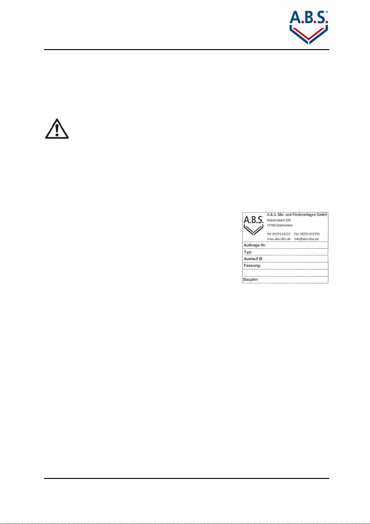
2.4 Nameplate............................................................................................................... 7
2.5 Maintenance............................................................................................................ 7
2.6 Storage Aeration..................................................................................................... 8
3 Room Layout.................................................................................................................. 9
3.1 Room size............................................................................................................... 9
3.1.1 Distance from walls.............................................................................................. 9
3.1.2 Distance from ceiling ........................................................................................... 9
3.2 Condition of the room.............................................................................................10
3.3 Room fixtures.........................................................................................................10
3.4 Room deaeration....................................................................................................11
3.5 Size / Storage Volume............................................................................................11
4 Scope of delivery...........................................................................................................12
4.1 Scope of delivery (standard)...................................................................................12
4.2 Optional Accessories..............................................................................................14
5 Assembly.......................................................................................................................15
5.1 Pre-Assembly of the feeds .....................................................................................15
5.2 Assembling feed tube with stay tube......................................................................16
5.3 Fixation ..................................................................................................................17
5.4 Assembling the extraction devices .........................................................................17
6 Final Inspection.............................................................................................................18
7 Extract from accident prevention regulations.................................................................19

Operating and Assembly Instructions – A.B.S. Flexilo MINI for wood pellets
General Information
Subject to technical change Issue 09/2016 Page 3 of 19
©A.B.S. Silo- und Förderanlagen GmbH
1 Note
Please read these Instructions prior to assembling the A.B.S. Flexilo MINI
for wood pellets.
1.1 Symbols used
Danger! This symbol identifies a hazard that could cause serious bodily injury or
even death if appropriate precautionary measures are not taken.
Caution: Risk of injury or damage to equipment!
Dangerous situations that can cause minor to serious bodily injury or damage to
equipment and property.
Risk of electric shock! Failure to observe the warning can endanger life and
limb through contact with electricity.
References and tips
1.2 Normative references
•ÖNORM M 7137: Wood pellets - Requirements for storage of pellets at the ultimate
consumer
•EN 303-5: Heating boilers for solid fuels
•EN14961-2: Wood pellets for non-industrial use
•ENplus – Handbook for the certification of wood pellets for heating use, version 2.0
•Sample fire ordinance 2005
•VDI guideline 3464 (green print 2012): storage of wood pellets by ultimate consumer
1.3 Pellet quality, Intended use
The Flexilo
for wood pellets is intended solely for the storage of wood pellets. The maximum
acceptable bulk good temperature is 50 °C.
If you want to store other materials you need to get in touch with the manufacturer
necessarily.
We assume use of quality pellets complying with EU-Norm EN 14961-2
respectively
complying with DINplus that have a diameter of 6 mm. According to the DEPV-guidelines
only certified ENplus A1 quality pellets are recommended.
Quality class A2 is used in larger boilers in excess of 100 kW like in the commercial area.
The quality classes are distinguished primarily by the ash content and the permissible ash
softening temperature. The boiler manufacturer must permit the use of the A2 quality pellets
in their boilers.
Important criteria of wood pellets according to the ISO 17225-2 from 2014:

Operating and Assembly Instructions – A.B.S. Flexilo MINI for wood pellets
General Information
Subject to technical change Issue 09/2016 Page 4 of 19
©A.B.S. Silo- und Förderanlagen GmbH
Quality A1
Quality A2
diameter (mm) 6 or 8
length(mm) 3,15 to 40
moisture content (% by mass) <=10
ash content (% by mass) <=0,7
<=1,2
mechanical strength (% by mass)
>=97,5
finest content (% by mass) <=1
overlength (40 – 45 mm) <=1
heating value (kWh/kg) 4,6 to
5,3
bulk density (kg/m³) >=600
600 – 700
nitrogen content (% by mass) <=0,3
<=0,5
sulphur content (% by mass) <=0,04
<=0,05
chlorine content (% by mass) <=0,02
ash fusion temperature* (C°) >=1200
>=1100
* This value is only mandatory for ENplus certified pellets. It refers to the temperature at
which the wood ash deforms and thus can lead to scorification in the combustion chamber.
Poor quality pellets can impair operation of your heating system and have an adverse effect
on the storage and conveying equipment. Only high-grade pellets can assure reliable and
problem-free operation of the pellet-fired boiler and the conveying systems. If necessary,
have the supplier confirm the quality of the pellets.
ENplus certificate
ENplus certified pellets are available for quality classes A1
and A2. Manufacturers and suppliers of high quality wood
pellets and further information can be found under
www.enplus-pellets.de.
1.4 Approvals and Compatibility to Pellet Boilers
There are approvals of various boiler manufacturers for the A.B.S. Flexilo.
Through individual solutions of extraction devices and conveying systems in special cases
connections to the silo can be created.
Please comply with your country-specific standards and directives regarding
assembly and operation of the silo! Observe the information contained in these
instructions! It is binding and must be observed.

Operating and Assembly Instructions – A.B.S. Flexilo MINI for wood pellets
General Information
Subject to technical change Issue 09/2016 Page 5 of 19
©A.B.S. Silo- und Förderanlagen GmbH
1.5 Warranty and Guarantee
The "General Terms and Conditions of Business of A.B.S.” apply in all cases. These are
available to the operator no later than upon conclusion of the sales agreement. Warranty and
liability claims associated with personal injury or property damage are excluded if they can
be attributed to any one or several of the following causes.
−Unintended and improper use of the equipment.
−Operation of the equipment when safety devices are defective, not properly attached or
when safety devices and guarding are not functioning properly.
−Failure to observe the information contained in the Operating Instructions with regard to
storage, transportation, assembly, start-up, operation, and maintenance.
−Unauthorized structural changes.
−Improperly performed repairs.
−Catastrophic incidents resulting from the action of a foreign object or force majeure.
−Use of not yet released additive pellets (PowerPlus, pelprotec ®, etc). Please contact us
for information on the current supply level.
−In case of white rust.
White rust can occur during transport, for example. Protect frame against water, water spray
is already enough to form white rust.
However, if this cannot be avoided, then the white rust can quite easily be removed with
RZ51 zinc cleaner.
The manufacturer’s warranty and guarantee are based on the assumption that the silo
system has been properly assembled and commissioned by qualified personnel.
Deficiencies and damage arising from improper assembly, start-up and operation are
excluded from any and all warranty and guarantee coverage.
To ensure operation of the system as intended, the manufacturer’s instructions must be
followed. In particular, the equipment must be operated with the pellets stipulated in Chapter
1.3.
Damage to the silo from rodents or attributable to other external forces is not covered by our
warranty.
Damage attributable to flying sparks caused by cutting and welding work is excluded from
warranty coverage.
The guarantee covers only the items supplied by us.
Only original replacement parts or parts expressly approved by the manufacture may be
installed in the system.

Operating and Assembly Instructions – A.B.S. Flexilo MINI for wood pellets
Safety Information
Subject to technical change Issue 09/2016 Page 6 of 19
©A.B.S. Silo- und Förderanlagen GmbH
2 Safety Information
Please observe the following safety information!
2.1 General safety information
Danger to life in the event of a dust explosion caused by electrostatic di
scharge
•The filling nozzle and frame of the silo must always be connected to the potential
equalization system of the building in order to prevent build-up of static electricity. If
several pipe segments are connected to one filling line, all of the connections must be
interconnected electrically to one another.
•The room where the silo is installed must not be hermetically sealed, since the
overpressure created during the filling process escapes into the storage room.
•An exhaust air opening of 200 cm² or rather according to VDI guideline 3464 in the
storage room is necessary. If necessary open a window during the filling process.
•Heating boilers and fuel supply systems need electricity to operate. Improper
installation can mean that life is endangered.
•When filling the silo with a tank truck, the boiler must always be switched off in time.
•Point out possible sources of danger to the customer. The currently valid fire
protection and VDI guidelines must be satisfied prior to start-up.
•In order to avoid hazards associated with improper handling of the system, have
installation, initial start-up and service performed only by suitably qualified personnel
in compliance with all applicable regulations and manufacturer's instructions.
•Use only metal piping with Ø DN 100 mm and a smooth inside edge for the extension
of the filling line (galvanized, without burrs or welding sputter; use of plastic pipes is
not allowed!).
•The filling-set and the filling hose of the tank truck should not be longer than 30 m.
•Keep the filling system within the building as short as possible in order to minimize the
physical load to which the pellets are subjected, thus keeping fines and powder
created by abrasion low. Avoid tight bends as much as possible!
•The fill coupling has to be accessible and unproblematicly reachable (without using
any ladders etc.) for the tank truck driver.
•Protect fabric silos from rodents
•Do not change any settings or make any modifications to the system; if these are
necessary, contact A.B.S. first to obtain approval.
•Knowledge of the operating instructions and maintenance procedures is a
prerequisite. Prior to start-up, please read these Operating Instructions carefully and
completely, and remember to observe the safety information in particular.

Operating and Assembly Instructions – A.B.S. Flexilo MINI for wood pellets
Safety Information
Subject to technical change Issue 09/2016 Page 7 of 19
©A.B.S. Silo- und Förderanlagen GmbH
2.2 Fire prevention
All fire prevention regulations must be satisfied prior to start-up. (subject to country-specific
modifications).
2.3 Earthing
Attention! Let the earthing of your pellet storage area be executed by a
specialized company.
•All conductive parts of the silo must be grounded expertly.
•In particular the removal system, the steel frame and the connecting armature have to be
earthed.
•The filling lines must also be connected conductive and grounded professionally with a
cable (4 mm ²) to the potential equalization conductor (by a qualified electrician for
example).
•Especially the earthing parts have to be connected to the potential equalization and/or the
main potential equalization with specific PA conductors.
2.4 Nameplate
The nameplate stating the calculated storage capacity must
be attached to the pellet silo at a readily visible location, e.g.
at the filling nozzle or on one of the frame’s legs. The
nameplate is included in the shipping documents that
accompany Flexilo
for wood pellets when it is delivered.
Nameplate with calculated storage capacity
2.5 Maintenance
Regular cleaning of the bearing is required to ensure continuous, trouble-free and safe
heating operation. The fines content and the wood dust should be removed.
When cleaning, please note the following:
•Enter storage areas only when in compliance with safety regulations: Switch off
heating and discharge system, adequately ventilate before entering.
•Clean the removal system prior to new filling of dust and debris. Wear dust mask of
filter class P2.
•Heat silo sack empty regularly and clean the silo sack through movement from dust
while the removal system is uninstalled.
Vacuum the storage out. In private storage, the cleaning can be done with
commercial vacuum cleaners with HEPA filters. The vacuum cleaner should not work
at the highest level to avoid overheating and to prevent ignition hazards.
•
For reasons of occupational health and safety, an industrial vacuum cleaner with filter
class M is required for cleaning pellet storages. Earth buried storage and all other
storages starting at a capacity of 40 tons may only be accessed with a CO warning
device.
•Until the next filling process please fill the silo manually with pellets in sacks (through
the manual filling nozzle).
•Please check if the silo has damages caused by rodents or other external influences.

Operating and Assembly Instructions – A.B.S. Flexilo MINI for wood pellets
Safety Information
Subject to technical change Issue 09/2016 Page 8 of 19
©A.B.S. Silo- und Förderanlagen GmbH
•The bolting of the steel frame should be checked as well.
•Please check the fastenings of the Filling and removal systems.
•Make sure that all other openings on the silo are closed.
After two to three deliveries
-
at least every two years
-
the time before the
next pellet delivery should be used to clean the storage.
Please observe the recommendations concerning the maintenance of the boiler
manufacturers.
2.6 Storage Aeration
Wood pellets are a fuel that is environmentally safe and from which no health risk arises, if
handled properly. Wood pellets can develop an odour depending on the type of wood used.
The reason for this lies in the extractive, the wood's own oils, fats and resins, which are
activated during the pressing process and slowly outgas in the following weeks or
decompose when in contact with the air. Compared to other wood products wood pellets
have a very large surface area and are heavily used in their cell structure by the pressing
process. The result is that the release of the volatile components is faster, especially in fresh
pellets and at high ambient temperatures. Emissions usually decrease after a few weeks and
the odour associated evaporates completely.
The emissions of wood pellets consist of volatile organic compounds (VOCs), carbon
monoxide (CO) and carbon dioxide (CO2). Among the VOCs are, for example, the so-called
terpenes that in rare cases occur and are responsible for a "chemical" odour (such as
turpentine). Other ingredients such as aldehydes and carbon monoxide can produce an
unhealthy effect and therefore should not enter into the living area. To avoid any risk, two
simple principles must be observed.
•The storage room, or the room where the final storage is set up, must be sealed off from
the living area.
•The storage room ventilation (> 200 cm ²) should be directly above the openings to the
outside or, if this is not possible, through openings in to a well-ventilated room.
Elaborate ventilation solutions are required for larger storages (> 10 t) and vent lines > 5 m.
These are described in detail in the VDI guideline 3464 "Storage of wood pellets at the end
user ".
Each pellet storage room or set up room for final storage must be ventilated.
The ventilation openings should be designed in a manner that they do not
end directly under windows or air intakes.

Operating and Assembly Instructions – A.B.S. Flexilo MINI for wood pellets
Room Layout
Subject to technical change Issue 09/2016 Page 9 of 19
©A.B.S. Silo- und Förderanlagen GmbH
3 Room Layout
Please observe the following planning steps; only in this way can
problem-free operation be assured.
Failure to comply can result in damage to the equipment and system
malfunctions or put individuals and equipment at risk.
Planning the room layout is a prerequisite and requirement for setting up the A.B.S. Flexilo
for wood pellets. The plans for the rooms must have already been given some thought when
ordering the silo. Nevertheless, prior to installation, check the dimensions and existing
conditions (see the next chapter).
Compliance with local regulations and proper construction of the building are the
responsibility solely of the purchaser of the equipment and are prerequisites for coverage by
the warranty and guarantee.
3.1 Room size
The required silo size depends on the size of the room. Please check the dimensions of both
the silo and the room prior to installation. The dimensions of the silo frame are stated on the
delivery documents.
The dimensions of the silo frame can be determined by measuring the steel parts:
Length of the frame = 980 mm
Width of the frame = 980 mm
Height of the frame = 1.220 mm
The silo and the removal units must be easily accessible for maintenance.
3.1.1 Distance from walls
A distance of 10 to 15 cm is required between the silo frame and walls in order to provide
ventilation at the back of the silo and protect against mechanical damage. Because of the
bulk nature of the pellets, the side walls of the silo may bulge slightly.
For the filling with pellet bags and the maintenance should be one side of the silo completely
accessible.
3.1.2 Distance from ceiling
A minimum distance of 20 cm is required between the upper edge of the silo frame and the
ceiling to provide space for the filling line. To prevent damaging the top fabric of the silo
during filling, no sharp or sharp-edge objects should be fastened to the ceiling.
In order that the filling with pellet bags is possible, see that it is enough distance between
frame edge and ceiling.

Operating and Assembly Instructions – A.B.S. Flexilo MINI for wood pellets
Room Layout
Subject to technical change Issue 09/2016 Page 10 of 19
©A.B.S. Silo- und Förderanlagen GmbH
3.2 Condition of the room
A stable supporting surface as the installation site is a prerequisite for setting up the silo. The
floor must be horizontal; if this is not the case, any unevenness must be corrected through
use of suitable underlay material (e.g.: steel plates). The load-bearing capacity of the floor
has to be checked according to the silo capacity.
For silos up to about 3.1 t, the plates at the bottom of the frame feet (stands) have
dimensions of 120x120 mm; starting at about 3.2 t, the dimensions are 140x140 mm. For
silos with a capacity of 8 t or higher, the load per frame feet (stand) can exceed 2,000 kg;
larger plates are available in such cases. Please consult the manufacturer directly with your
questions in this regard and check the permissible floor loading.
The base connectors must be secured by means of anchor bolts.
Rooms with moisture levels normally found in cellars do not present any problems; however,
condensation must not occur. In case of humidity the room must be ventilated properly. The
silo fabric is air-permeable and may cause the wood pellets to absorb humidity at the silo
walls.
Make also sure that humidity does not enter the filling pipe if it is directed from outside into
the storage area.
When setting up outdoors, the following applies:
A properly levelled and stable concrete foundation must be available for anchoring the frame
feet (stands). The foundation can be designed as a slab with strip footing or as individual
foundations. The silos should be protected against moisture from below. For outdoor
installation, the frame feet (stands) should be galvanized. The silo must be protected from
direct sunlight and the effects of weather (e.g. place in a wood or metal enclosure or a
coating).
3.3 Room fixtures
Room fixtures such as drain pipes, ceiling hooks, water pipes, etc. must already be
considered in the planning phase, or be removed before installing the Flexilo
for wood
pellets, if these interfere with the installation and proper operation of the silo.
There must be no sharp or sharp-edged objects near the silo bag. If it is not possible to
remove such objects, they must be covered.
There must be no lamps, lines of any kind, sharp, hot or damp contact surfaces above the
pellet silo.

Operating and Assembly Instructions – A.B.S. Flexilo MINI for wood pellets
Room Layout
Subject to technical change Issue 09/2016 Page 11 of 19
©A.B.S. Silo- und Förderanlagen GmbH
3.4 Room deaeration
The conveying air used to blow the pellets into the pellet silo must be allowed to escape
during filling by opening a window or door.
A cross-sectional area of at least 200 cm² or rather according to the VDI guideline 3464 is
necessary for this purpose. Windows, unused chimneys and openings in the masonry are
permissible for this purpose.
Caution required when venting lines > 5 m. Artificial ventilation necessary -
according to VDI guideline 3464 using a fan.
The conveying air escapes through the fabric on the top of the silo. Thus, no exhaust system
for the conveying air is needed when aerating the Flexilo.
Only on customer request the Flexilo
for wood pellets can be supplied with a filling line and
an exhaust air line in case of rooms without exhaust air or in specific cases.
But from the technical aspect this is not necessary and gives no advantage.
Please provide for a power connection for the suction blower when installing a suction line.
This can also be combined with an automatic shut-off function for the heating system.
In such a case, be sure to observe the separate filling instructions for A.B.S.
silos for wood pellets.
3.5 Size / Storage Volume
The storage area / the pellet storage should contain an annual need of pellets.
Thus the need for supply in winter at higher prices is avoided. At the same time requirements
are created to empty the storage and carry out cleaning work during the summer months.
Heat requirement in kWh/year 5000 10000 20000
Consumption of fuel oil in l/year 625 1250 2500
Pellet requirement in kg/year 1250 2500 5000

Operating and Assembly Instructions – A.B.S. Flexilo MINI for wood pellets
Scope of delivery
Subject to technical change Issue 09/2016 Page 12 of 19
©A.B.S. Silo- und Förderanlagen GmbH
4 Scope of delivery
The Flexilo MINI for wood pellets consists of a steel frame,
which is shipped bundled on a pallet, and a silo bag, which
is packed in a carton together with accessories and
hardware required for assembly.
Delivery of the components
4.1 Scope of delivery (standard)
Pos.
Illustration
Description and
quantity
1
1 each Silo bag
of the appropriate size
packed in a plastic
bag
2
4 each feet tube
3
8 each stay tube
4
4 each feed
connectors

Operating and Assembly Instructions – A.B.S. Flexilo MINI for wood pellets
Scope of delivery
Subject to technical change Issue 09/2016 Page 13 of 19
©A.B.S. Silo- und Förderanlagen GmbH
5
4 each head connectors
6
4 each middle connectors
7
1 x Nameplate
(included in delivery note-bag)
Table listing items included in the shipment

Operating and Assembly Instructions – A.B.S. Flexilo MINI for wood pellets
Scope of delivery
Subject to technical change Issue 09/2016 Page 14 of 19
©A.B.S. Silo- und Förderanlagen GmbH
4.2 Optional Accessories
Depending on boiler-type resp. on the conveying system of the heating system; different
extraction systems are offered for the Flexilo MINI for wood pellets.
Pos.
Illus
tration
Description
1
Exhausting box
For direct access of the suction-hoses from
the suction-blower. This system does not work
with all suction-blowers.
Accessories: Tension band, Tension ring,
Bottom-part of the box, Upper-part of the box
2
Screw boxes
To adapt different screw systems
Accessories: Tension band, Locking-gate-
valve
Optional accessories
Pay attention to the installation notes for screws and spiral conveyors, avoid bends
and radii, transfer stations and long transport distances.
With suction conveyor systems it is important to pay attention to the maximum
conveying distance. Mostly < 25 m. Ascends in the conveying line have a positive
effect on transport.
Heed the assembly instructions of the respective conveyor systems.
When the exhausting box will be installed the suction hoses are supposed to be laid
on top of each other.

Operating and Assembly Instructions – A.B.S. Flexilo MINI for wood pellets
Assembly
Subject to technical change Issue 09/2016 Page 15 of 19
©A.B.S. Silo- und Förderanlagen GmbH
5 Assembly
5.1 Pre-Assembly of the feeds
The feed tubes (the four long) will be connected with the feed plates and move over each of
the feed a middle connector.
Afterwards put the head connectors on the same pipes.
Do not start assembling the silo until you have become familiar with the situation at
the installation site and the room layout discussed in Section 3.

Operating and Assembly Instructions – A.B.S. Flexilo MINI for wood pellets
Assembly
Subject to technical change Issue 09/2016 Page 16 of 19
©A.B.S. Silo- und Förderanlagen GmbH
5.2 Assembling feed tube with stay tube
At first push the stay tubes through the provided loops on the silo.
After that you connect the stay tubes with the feed tubes side for side.

Operating and Assembly Instructions – A.B.S. Flexilo MINI for wood pellets
Assembly
Subject to technical change Issue 09/2016 Page 17 of 19
©A.B.S. Silo- und Förderanlagen GmbH
5.3 Fixation
Tighten the screw connections strongly.
Fix the frame on the ground.
Ground all steel parts, as described in chapter "Grounding".
5.4 Assembling the extraction devices
Finally, you must mount the extraction system supplied with the silo (suction box, screw box).
The extraction unit should show in the direction of the boiler. This is especially important with
rigid augers
Exhausting box
•The exhausting box consists of two parts: the upper section
with emergency slide gate and the lower section with the
discharge neck.
•Using the clamp ring provided, connect the upper and lower
sections together such that the pressure relief device points in
the direction of the extraction line.
•Place the unit on an assembly aid.
•Pull the silo outlet over the upper beaded rim of the upper
section and secure it above the seam with the tension band.
•The extraction hose must be attached to the lower neck and the
return air hose to the upper neck.
•If it is necessary to adjust the extraction rate, close the
emergency slide gate, use the suction blower to start a flow of
pellets and slowly open the emergency slide gate. Upon
reaching a satisfactory pellet flow rate, leave the emergency
slide gate in the current position.
•If possible with regard to the conveying rate, remove the
emergency slide gate completely and close off the slot with a
piece of tape.
•Pay special attention to proper adjustment of the cyclone flap
on the suction blower
Screw box
•Use a similar procedure with a screw box.
•Place the unit on an assembly aid.
•Pull the silo outlet over the upper beaded rim and secure it
above the seam with the tension band.
•Augers or spiral conveyors as well as other special inserts from
various manufacturers can, upon approval, be installed in
different auger feed boxes.
Extraction systems
The silo removal units shall be NEVER fastened to the floor as this can lead to sound
transmissions during removal.
All removal units have an emergency or locking gate to remove the dust part regularly.

Operating and Assembly Instructions – A.B.S. Flexilo MINI for wood pellets
Final inspection
Subject to technical change Issue 09/2016 Page 18 of 19
©A.B.S. Silo- und Förderanlagen GmbH
6 Final Inspection
Position of the extraction device
Check that the discharge neck is centered in the silo. Adjust the silo or extraction unit so that
the silo is centered exactly over the point of discharge.
•Check that all individual parts are bolted together properly.
•Check that the top bars and frame legs (stands) are not askew (use a spirit level).
•Check that the silo bag is suspended centrally.
•Check that the filling and extraction systems are attached correctly.
•Check that the nameplate is attached in a clearly visible location on a frame leg or the
filling line.
•Check the room layout (wall and ceiling clearance, condition of the room, fixtures in the
room, room ventilation).
•Have the frame earthed by a licensed electrician. The earth resistance must not exceed
106 Ω.
•Check that the silo frame is anchored to the floor properly.
•Check the stability of the silo frame overall.
•Tighten the clamping rings and tension bands on the extraction system once again.
Use the following check list to ensure proper assembly of the silo.
FALSCH
RICHTIG FALSCH
RICHTIG
Right Wrong

Operating and Assembly Instructions – A.B.S. Flexilo MINI for wood pellets
Extract from accident prevention regulations
Subject to technical change Issue 09/2016 Page 19 of 19
©A.B.S. Silo- und Förderanlagen GmbH
7 Extract from accident prevention regulations
Agricultural Trade Association for Central and Eastern Germany
OT Hönow Hoppegartener Str. 100 15366 Hoppegarten
§ 1 Principles
These accident prevention guidelines shall apply to storage facilities in which loose
bulk and solid materials shall be stored.
Instruction guidelines
1. Storage facilities include bulk material silos for holding e.g. powdery, grainy or shredded
materials.
§ 2 Set up
The contractor must ensure that
1. Storage facilities are set up such that persons are not endangered by operation in
accordance with their intended purpose and that injured parties can be rescued,
2. Control stations for silos, under which vehicles shall drive, are positioned outside of
the traffic access area,
3. Pneumatic connection points for the storage facilities to be filled are at an easily
accessible height,
4. Filling, control and removal openings, filling and removal fittings and extraction
valves are arranged and
designed such that
− Insured parties can operate these without risk
− Insured parties will not be injured by the storage material while it is being filled into
the storage facility
− The material to be stored can be filled and removed without any disruption
− Electro-static charge cannot build up,
5. Silos made of UV-light-sensitive materials shall be positioned such that they are
protected from UV radiation,
6. Suitable fittings are attached on storage facilities intended for the use of additional
operational facilities for their installation and removal,
7. The storage capacity and permissible filling weight are specified on bulk material
silos,
8. The access height is clearly visible on storage facilities under which vehicles can
drive,
Instruction guidelines re item 1
1. If storage facilities are set up as part of self-build work, a specialist such as an architect or
master bricklayer should confirm that the building and foundations are suitable for
accommodating a silo and the associated loads.
As a rule, this is required for silos,
− that are not self-supporting,
− for which a statically analyzed supporting structure is not supplied,
− that shall be installed on existing foundations or building ceilings,
− that shall be hung from existing building ceilings or in
installed in roofs (sack silos).
Incidentally, please observe the following rules and regulations:
State building regulations
More extensive water management requirements
DIN 1055-6 Assumed loads for buildings; Section 6: Loads in silo cells
DIN EN ISO 14122 Permanent means of access to machinery
DIN 18799 Safety ladders on building facilities
2. Insofar as silos must be climbed into in accordance with its intended operation,
− Openings with an inside width of at least 60 cm
− Access and exit aids, e.g. in the form of safety ladders or step irons are necessary.
3. To rescue casualties from silos, in which life-threatening vapours can develop, it is
necessary to include measures such as accessing the silo wearing breathing apparatus and
hoist rings for attaching a rescue rope.
4. Additional hazards may arise e.g.
− during the pneumatic filling due to connection lines breaking or leaking, or due to the
unintentional opening of the hose couplings; the connection piecesmust be arranged such
that the hose connection are as short as possible to the container vehicle.
Instruction guidelines re item 6
1. Additional operating facilities can include blower pipes, removal/distribution equipment and
access fixtures.
2. Suitable facilitiesfor the safe installation and removal can include lifting and hauling fixtures
and swivelling jib.
§ 3 Climbing equipment
The contractor must ensure that
1. Storage facilities, whose upper edges are more than 1 m above the floor and must be
mounted for regular operational work, must be equipped with secure climbing
equipment
Instruction guidelines re item 1
The requirement is regarded as fulfilled for silos, when e.g. stairs with railings are attached on
the free sides or safety ladders are attached. Apart from that, Paragraphs 7 and 8 of the
accident prevention guidelines "Workplaces, building sites and facilities" (VSG 2.1) must be
observed.
§ 5 Protection from falling
The contractor must ensure that
1. Storage facilities must protected from persons falling in, in the event of the fall height
being greater than 1 m,
2. Storage facilities in a traffic area with an upper edge at floor level must be protected
from vehicles accidentally falling in,
3. Storage facilities that can be accessed at the height of the upper edge must be
secured again persons falling in, if the upper edge is higher than 1 m above the ground,
Instruction guidelines re item 2
Protection against vehicles falling in can include e.g. 30 cm high approach pedestal.
Instruction guidelines re item 3
1. As protection against person falling in, a parapeted railing 1m to 1.30 m high, knee rails at
30 cm to 50 cm and a 5 cm high foot bar is adequate. Flexible covers
– such as plastic sheeting and similar are not regarded as adequate protection from persons
falling in.
§ 6 Filling and removal
The contractor must ensure that
1. Silos may only be filled with the material and with the permissible quantity as
specified in the user guide.
§ 7 Access and saving casualties
The contractor must ensure that
1. Only persons aware of the associated risks may access the silo
2. The necessary aids to secure people accessing the silo are kept available in
proximity of the access area and the insured persons are familiar with the usage of said
aids
3. That silo is not accessed during the mechanical emptying process or emptying due
to gravity.
(2) Before and during any access time in the silo, it must be ensured that
− no suffocation or poisoning hazard will arise
− adequate air is available
− Operational facilities are reliably protected from being activated.
Instruction guidelines
5. A lockable main switch is an example of providing reliable protection against accidental
activation of the operational facilities. Operational facilities in this sense are removal and
distribution equipment.
(3) It is only permissible to access bulk material silos, when the person accessing is
roped up and the rope is secured outside of the silo and said person is secured by two
persons.
(4) Access to recover casualties is only permitted when the person accessing the silo is
secured such that, he/she can leave the danger at any time and suitable aids for
ensuring air to breather are used.
(5) In the event of nausea, the storage facility must be left immediately.
§ 8 Installation and removal of additional operational facilities The contractor must
ensure that suitable equipment is available and used for the installation and removal of
additional operational facilities.
Instruction guidelines
Please observe § 2, Item 6.
§ 10 Warning signs
The contractor must ensure that a warning sign indicating the type of risks is attached
at a clearly visible point on storage facilities in which dangerous gases or dusts can
build up. This is also valid for removal stations in buildings.
Instruction guidelines
§ 11 Monitoring bulk material silos
The contractor must ensure that bulk material silos are regularly examined as follows
− The silo walls to ensure these are sealed and have no tears or pitting corrosion,
− The load-bearing construction and layers for deformation or displacement of the
brackets,
− On sack silos: the load-bearing frame, the suspension system, the seams
and UV light protection features.
Abridgement of UV
LagerstättenVSG 2.2
vom 1. Januar 2000
Stand 14. Dezember 2007
Table of contents
Other A.B.S. Industrial Equipment manuals
Popular Industrial Equipment manuals by other brands

Dupont
Dupont IntegraTec P Series Assembly instructions

Pentair
Pentair Aurora 1080 Series INSTRUCTION, INSTALLATION, MAINTENANCE AND REPAIR MANUAL

turck
turck BL ident TW-R16-B128-Ex manual

ABB
ABB HT601971 Operation manual

Team
Team SILK AX14-45 instruction manual

SICK
SICK Flexi IO XTDO1 operating instructions