A/DA ADA-7240 User manual
User manual
ADA-7240
RS-485 / RS-422 to Multidrop Fiber Opti Converter
1
ADA-7240
Copyright © 2001-2017 CEL-MAR sp.j. io_ada-7240_en_v .22

Contents
1. GENERAL INFORMATION......................................................................................................................................................................
1.1. WARRANTED INFORMATION.......................................................................................................................................................
1.2. GENERAL CONDITIONS FOR SAFE USE....................................................................................................................................
1. . CE LABEL.......................................................................................................................................................................................
1.4. ENVIRONMENTAL PRESERVATION............................................................................................................................................
1.5. SERVICE AND MAINTENANCE.....................................................................................................................................................
1.6. PACK CONTENTS..........................................................................................................................................................................
2. PRODUCT INFORMATION.....................................................................................................................................................................
2.1. PROPERTIES.................................................................................................................................................................................
2.2. DESCRIPTION................................................................................................................................................................................ 4
2. . ISOLATION..................................................................................................................................................................................... 5
. INSTALLATION....................................................................................................................................................................................... 5
.1. ASSEMBLING................................................................................................................................................................................. 5
.2. CONNECTION TO RS485/RS422 BUS.......................................................................................................................................... 5
.2.1. CONNECTION TO 4-WIRE RS422 BUS...............................................................................................................................5
.2.2. CONNECTION TO 4-WIRE RS485 BUS...............................................................................................................................6
.2. . CONNECTION TO 2-WIRE RS485 BUS............................................................................................................................... 6
.2.4. LINE TERMINATION Rt ON RS485/RS422 BUS.................................................................................................................. 6
. . CONNECTION FIBRE-OPTIC BUS................................................................................................................................................ 7
. .1. WIRING TOPOLOGY FIBER OPTIC BUS............................................................................................................................. 7
. .2. EXAMPLES OF CONNECTION THE CONVERTER TO FIBER OPTIC BUS........................................................................8
.4. POWER SUPPLY CONNECTION.................................................................................................................................................. 9
4. CONFIGURATION................................................................................................................................................................................... 9
4.1. OPERATING MODE SETTING....................................................................................................................................................... 9
4.2. DEFAULT SETTING....................................................................................................................................................................... 9
5. ACIVATION.............................................................................................................................................................................................. 9
5.1. DESCRIPTION OF SIGNALLING LEDS......................................................................................................................................... 9
5.2. TROUBLESHOOTING.................................................................................................................................................................... 9
6. VERSIONS............................................................................................................................................................................................ 10
7. SPECIFICATION................................................................................................................................................................................... 10
2
ADA-7240

1. GENERAL INFORMATION
Thank you for your purchase of CEL-MAR Company product. This product has been completely tested and is covered by a two year
warranty on parts and operation from date of sale.
If any questions or problems arise during installation or use of this product, please do not hesitate to contact Technical Support at +48
41 62-12-46 or e-mail support@cel-mar.pl.
1.1. WARRANTED INFORMATION
ADA-7240 converter is covered by a two year warranty from date of sale. In case of being damaged it will be repair or the damaged
component will be replace. The warranty does not cover damage caused from improper use, materials consumption or any
unauthorized changes. If the product does not function (is damaged), or not operate in accordance with the instructions, will be
repaired or replaced.
All warranty and no warranty repairs must be returned with paid transport and insuring to the CEL-MAR Company.
CEL-MAR Company under no circumstances won't be responsible for ensuing damage from improper using the product or as a result
of random causes: the lightning discharge, the flood, the fire and the like.
CEL-MAR Company is not be held responsible for damages and loss including: loss of profits, loss of data, pecuniary losses ensuing
from using or the impossibility of using this product.
In specific cases CEL-MAR Company discontinue all warranties and in particular do not follow the user manual and do not accept
terms of warranty by the user.
1.2. GENERAL CONDITIONS FOR SAFE USE
The device should be installed in a safe and stable places (eg, electroinstallation cabinet), the powering cable should be arranged so
as not to be exposed to trampling, attaching, or pulling out of the circuit.
Do not put device on the wet surface.
Do not connect devices for nondescript powering sources,
Do not damage or crush powering wires.
Do not make connection with wet hands.
Do not adapt, open or make holes in casings of the device!
Do not immerse device in water or no other liquid.
Do not put the fire opened on device sources: candles, an oil lamps and the like.
Complete disable from the supply network is only after disconnecting the power supply circuit voltage.
Do not carry out the assembly or dis-assembly of the device if it is enabled. This may result to short circuit and damage the device.
The device can not be used for applications that determine human life and health (eg. Medical).
ATTENTION!!!
The devi e is equipped in the laser transmitter.
The radiation emitted by the laser transmitter is harmful to the eyes!
Under no ir umstan es should never look to at the un overed slot, to whi h it is not onne ted the fiber opti
onne tor.
The manufa turer is not responsible for used not in a ordan e with the instru tion manual.
The user manual is an integral part of the devi e and with it is delivered to users.
1.3. CE LABEL
The CE symbol on the device CEL-MAR means compatibility with electromagnetic compatibility Electromagnetic
Compatibility Directive EMC 2014/30/WE. Declaration of Conformity is available by contact with Technical Service
(email: support@cel-mar.pl; phone: +48 41 62-12-46).
1.4. ENVIRONMENTAL PRESERVATION
This sign on the device inform about putting expended device with other waste materials. Device should send to the
recycling. (In accordance with the act about the Electronic Appliance Expended from day 29 of July 2005)
1.5. SERVICE AND MAINTENANCE
The ADA-7240 converter does not require the servicing and maintenance.
Technical support is available at number +48 41 62-12-46 in 8.00-16.00, from Monday to Friday or e-mail support@cel-mar.pl.
1.6. PACK CONTENTS
The converter is delivered with the user manual and resistors: Rt=120W (2 pcs).
2. PRODUCT INFORMATION
2.1. PROPERTIES
●Fibre-Optic to RS485 / RS422 conversion,
●Regeneration of Fiber Optic signal – Fiber Optic repeater,
●Fibre-Optic connection via fore fibre connectors type: ST® * or SC – transmitter and receiver for an optical wavelength from 792nm
to 865 nm or SMA – transmitter and receiver for an optical wavelength from 640nm to 675nm.
●Fibre Optic line: 2 mutimode optical fibres eg. type 50/125 mm, 62,5/125 mm, 100/140 mm, 200 mm HCS, 1mm POF,
●Transmission of RX, TX signals,
●Baud rate up to 2Mbps.
●Operating on RS-485 network 2 or 4 wire,
●Automatic direction data flow control on RS485 network,
●Transparent for all protocols: MODBUS, DNP, PROFIBUS and other,
ADA-7240
●External power supply 10 - 0 VDC stable min. W,
●1kV= or kV= galvanic isolation between RS485/RS422 interface and power supply,
●Connection RS485/RS422 network and power supply via screw terminal block,
●Connection Fiber Optic network via fibres optic connectors type: ST® *(850nm), SC(850nm), SMA(650nm),
●Protection against power supply reverse connection,
●Implemented overvoltage protection on RS422/485 network,
●DIN 4 880 standard - mounting in typical electro-installation unit,
●Rail mounting according to DIN 5 / TS 5 standard,
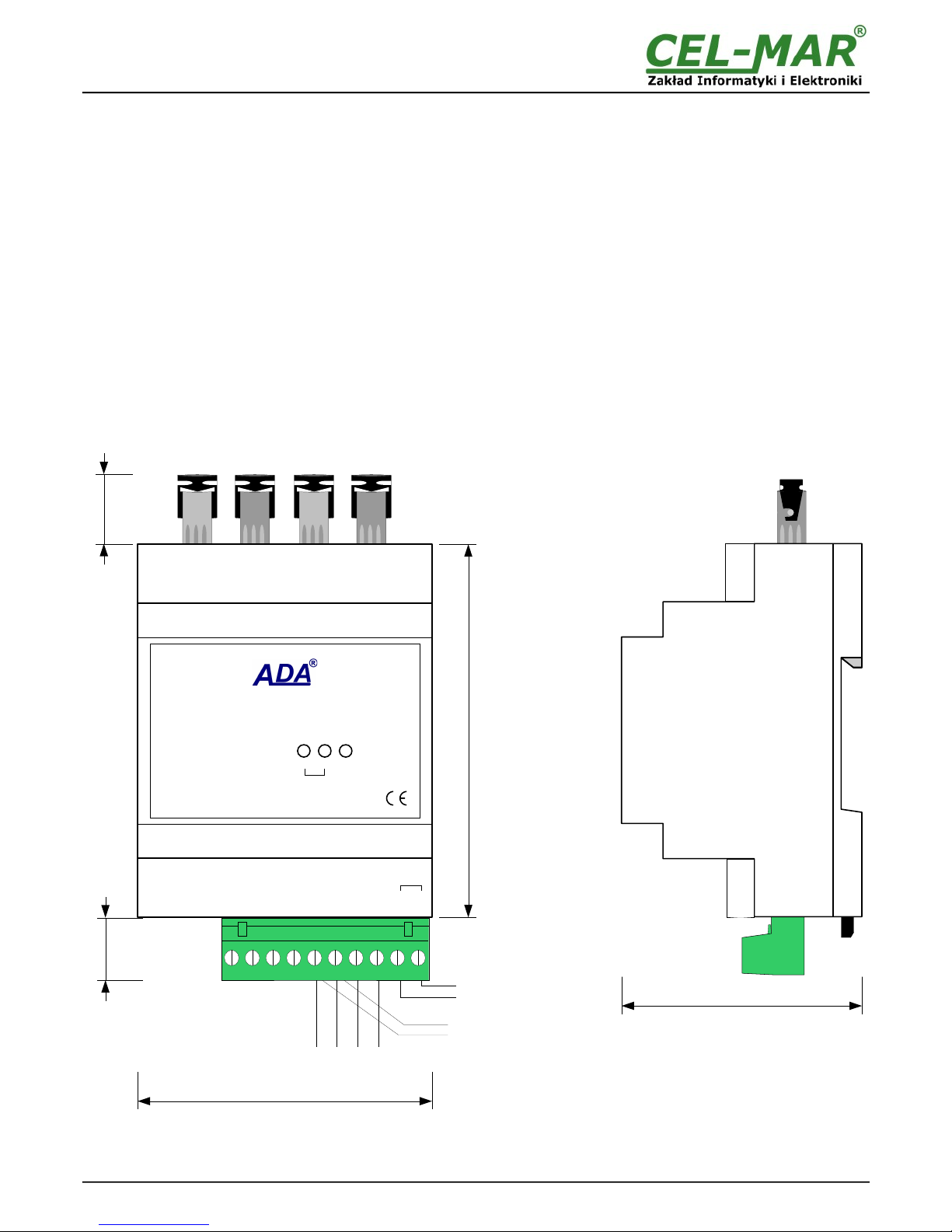
●Dimensions of casing contour (W x H x D) 71mm x 90mm x 58mm,
2.2. DESCRIPTION
Multidrop Fiber Optic Converter ADA-7240 is used for creation of fiber optic bus, for connection of RS485/422 interface devices quite
distant from each other eg. Computers, controllers etc. Conversion between fiber optic RS485/422 is without interfering with the data
format. The use of fibre-optic provides complete isolation between connected devices and resistance to interference on the
transmission bus. Fiber optic connection is made by the use of two fibres. ADA-7240 can be use also for extend the fiber optic bus for
next part 2500m because the converter also complies functions of fiber optic repeater.
ADA-7240 is equipped with screw terminal block for connection of RS485/422 and power connections. It supports baud rates up to
2Mbps on 2-wire or 4-wire RS-485 bus via one or two pairs of twisted pair, connected to the screw terminals block. The device uses to
operate lines RX +, RX-, TX +, TX-.To RS485 bus built on the ADA-7240 can be connected 2 devices operating in half duplex mode
or full duplex mode and to RS422 bus two devices operating in half duplex mode. Overvoltage protection was made on base safety
diodes and fuses on each RS485/RS422 lines.
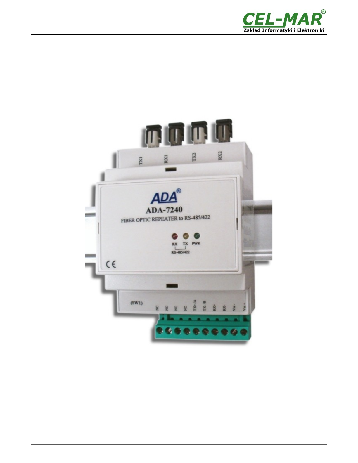
Fig. 1. View of ADA-7240.
4
ADA-7240
15mm
Power Supply
10 - 0 VDC
RS-485 4-WIRE
or RS-422
90mm
71mm
TX 1
RX 2
RX 1
TX 2
17mm
NC
Tx + / A
Tx - / B
Rx +
Rx -
NC
NC
NC
RS-485
2-WIRE
ADA-7240
PWRTXRX
FIBER OPTIC REPEATER to RS-485/RS-422
RS485/RS422
(SW1)
58mm
V -
V +
10 – 0
VDC
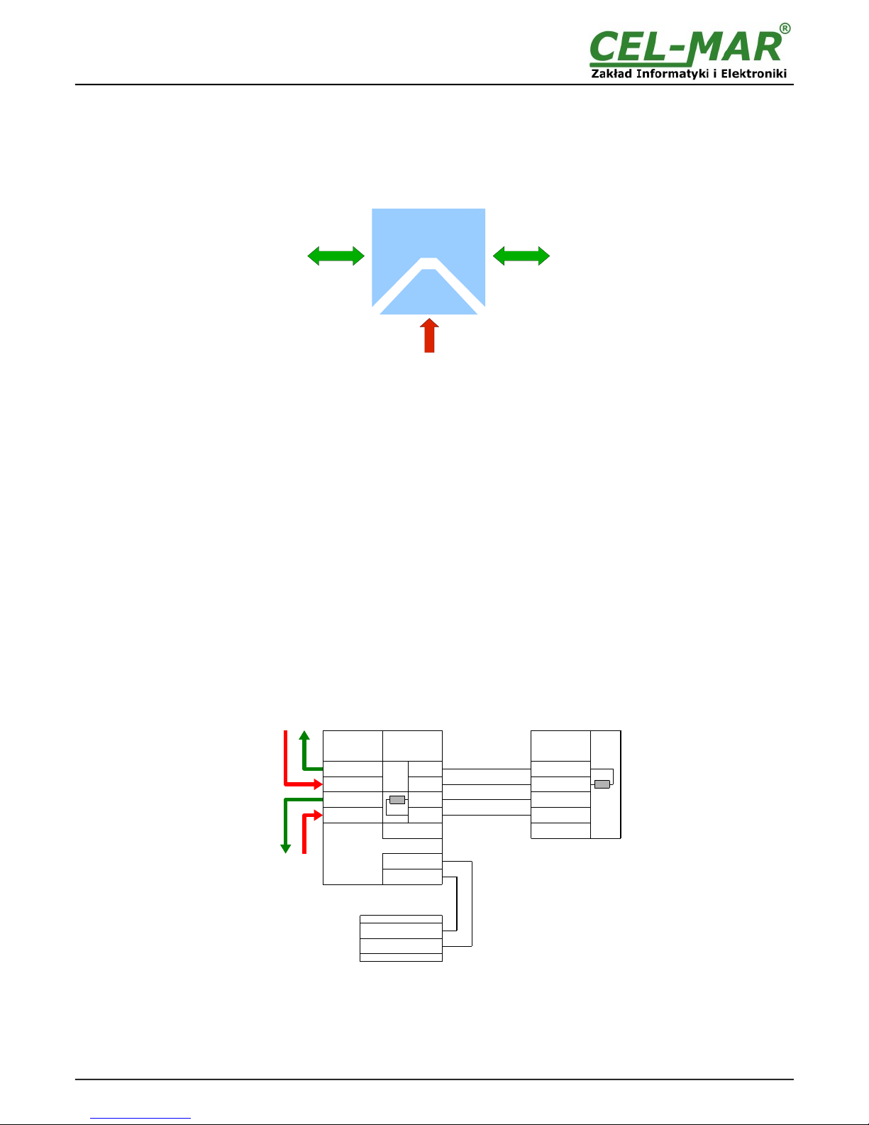
2.3. ISOLATION
Converter ADA-7240 has galvanic isolation between power circuit and communication interfaces (RS485/422 and Fiber Optic) on level
1kV= or kV=, depend on version described in section below.
Fig. 2. Isolation stru ture.
3. INSTALLATION
This chapter will show how to connect ADA-7240 to RS485/422 bus, Fibre-Optic and power supply and how to use it.
In the purpose of minimization of disruptions from environment is being recommended to:
●apply multipair type shielded cables, which shield can be connected to the earthing on one end of the cable,
●arrange signal cables in the distance not shorter than 25 cm from powering cables,
●apply cable of adequate cross-section due to voltage drops for converter powering,
●use Interference suppression filters for power supply converters that are installed within a single object.
●not supply converter from power circuit device that generates large impulse interference such as transmitters, contactors,
3.1. ASSEMBLING
The ADA-7240 converter case is adapted to assembly on TS- 5 (DIN 5) rail. To install converter should mount device on the rail
upper part of the case then press bottom part to hearing characteristic „Click” sound.
3.2. CONNECTION TO RS485/RS422 BUS
RS485/RS422 interface at ADA-7240 converter is available on terminal block described as: Tx+/A, Tx-/B, Rx+, Rx-. ADA-7240 support
operating on RS422 bus and RS485. Both buses need proper cabling.
3.2.1. CONNECTION TO 4-WIRE RS422 BUS
Fig. 3. Example onne tion of RS422 devi e .
5
ADA-7240
Device with RS422
interface
RS422
onne tor
TX+
TX-
GND
RX+
RX-
Rt
TX2
RX2
TX1
RX1
FO
onne tor
Rt
RX+
RX-
GND
TX+
TX-
V +
V -
V -
V +
RS422
onne tor
Power Supply
ADA-7240
Multimode optical
fibers type:
50/125um,
62,5/125 um,
100/140um,
200umHCS,
Plastics
POF/1mm,
Power Supply
10 - 0VDC
Fibre-Optic RS485/422
POWER ISOLATION
Table of contents
Popular Media Converter manuals by other brands


H&B
H&B TX-100 Installation and instruction manual

Bolin Technology
Bolin Technology D Series user manual

IFM Electronic
IFM Electronic Efector 400 RN30 Series Device manual

GRASS VALLEY
GRASS VALLEY KUDOSPRO ULC2000 user manual

Linear Technology
Linear Technology DC1523A Demo Manual

Lika
Lika ROTAPULS I28 Series quick start guide

Weidmuller
Weidmuller IE-MC-VL Series Hardware installation guide

Optical Systems Design
Optical Systems Design OSD2139 Series Operator's manual

Tema Telecomunicazioni
Tema Telecomunicazioni AD615/S product manual

KTI Networks
KTI Networks KGC-352 Series installation guide

Gira
Gira 0588 Series operating instructions

Lika
Lika SFA-5000-FD user guide