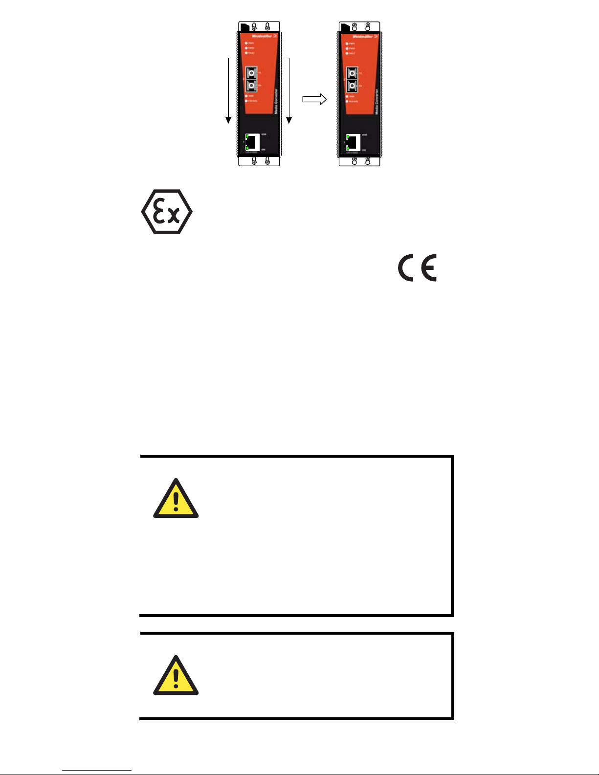
Weidmuller IE-MC-VL Series Manual

Media Converter – Value Line
IE-MC-VL Series
Hardware Installation Guide
Third Edition, June 2011
1243430000/02/06.11
Please note:
This document and any further product information
- if available - can be downloaded at the internet
link:
http://www.weidmueller.com/downloads
Copyright Notice
Copyright ©2011 Weidmüller Interface GmbH & Co. KG
All rights reserved.
Reproduction without permission is prohibited.

- 2 -
Overview
Weidmüller Media Converter, which is specially designed for reliable
and stable operation in harsh industrial environments, provides
industrial grade media conversion between 10/100BaseT(X) and
100BaseFX. The IE-MC-VL Series reliable industrial design is
excellent for keeping your industrial automation applications running
continuously, and comes with a relay output warning alarm to help
prevent damages and losses.
This product is available in an operating temperature range from 0 to
60°C or -40 to 75°C, and is designed to withstand a high degree of
vibration and shock. The rugged hardware design makes IE-MC-VL
Series perfect for ensuring that your Ethernet equipment can
withstand critical industrial applications, such as in hazardous
locations (Class 1 Division 2/Zone 2), and complies with FCC, TÜV,
UL, and CE Standards.
Package Checklist
Weidmüller Media Converter is shipped with the following items. If any
of these items is missing or damaged, please contact your customer
service representative for assistance.
yWeidmüller Media Converter
yHardware Installation Guide
Features
ySupports 10/100Base-TX auto-negotiation and auto-MDI/MDI-X
yMulti mode, single mode with SC or ST fiber connector available
ySupports Link Fault Pass-Through
yRelay Output alarm when a port breaks or the power fails
yRedundant 24 VDC (12 to 45 VDC) power inputs, DIN-Rail or panel
mountable
yOperating temperature range from 0 to 60°C (optional with
extended operating temperature from -40 to 75°C)

Panel Layout of
IE-MC-VL Series
1. Grounding screw
2. Terminal block for power
input PWR1/PWR2 and
relay output
3. Heat dissipation orifices
4. Dip switch
5. Power input PWR1 LED
6. Power input PWR2 LED
7. Fault LED
8. 100BaseFX (ST connector)
Port
9. FX port’s 100 Mbps LED
10. FX port’s Full
Duplex/Collision LED
11. TP port’s 100 Mbps LED
12. 10/100BaseT(X)
13. TP port’s 10 Mbps LED
14. Article Number
15. 100BaseFX (SC connector)
Port
16. Screw hole for wall mounting kit
17. DIN-Rail mounting kit
Front Panel View
IE-MC-
V
L-1TX-1ST
Front Panel View
IE-MC-
V
L-1TX-1SC
/
1SCS
Top Panel View
Rear Panel View
- 3 -

- 4 -
Mounting Dimensions
DIN-Rail Mounting
The aluminum DIN-Rail attachment plate should be fixed to the back
panel of Weidmüller Media Converter when you take it out of the box.
If you need to reattach the DIN-Rail attachment plate to the device,
make sure the stiff metal spring is situated towards the top, as shown
in the figures below.
STEP 1:
Insert the top of the DIN-Rail into
the slot just below the stiff metal
spring.
STEP 2:
The DIN-Rail attachment unit will
snap into place as shown below.

metal
spring
DIN-Rail
metal
spring
DIN-Rail
To remove the Media Converter from the DIN-Rail, simply reverse
Steps 1 and 2 above.
Wall Mounting (Optional)
For some applications, you will find it convenient to mount the Media
Converter on the wall, as illustrated below.
STEP 1:
Remove the aluminum DIN-Rail attachment plate from the device,
and then attach the wall mount plates, as shown in the diagrams
below.
⇒
STEP 2: Mounting the Media Converter on the wall
requires 4 screws. Use the Media Converter, with
wall mount plates attached, as a guide to mark the
correct locations of the 4 screws. The heads of the
screws should be less than 6.0 mm in diameter, and
the shafts should be less than 3.5 mm in diameter, as
shown in the figure at the right.
NOTE Test the screw head and shank size by
inserting the screw into one of the keyhole
shaped apertures of the Wall Mounting
Plates, before it is screwed into the wall.
Do not screw the screws in all the way—leave a
space of about 2 mm to allow room for sliding the wall
mount panel between the wall and the screws.
6.0 mm
3.5 mm
STEP 3: Once the screws are fixed in the wall, insert the four screw
heads through the large parts of the keyhole-shaped apertures, and
then slide the Media Converter downwards, as indicated below.
Tighten the four screws for added stability.
- 5 -

II 3G
ATEX Information
1. Certification number DEMKO 11 ATEX1106692x
2. Ambient range (-40°C ≤Tamb ≤75°C)
3. Certification string (Ex nC nL IIC T4)
4. Standards covered ( EN60079-0:2006, EN60079-15:2005)
5. The conditions of safe usage:
yThe Ethernet Communication Devices are to be mounted in an
IP54 enclosure and used in an area of not more than pollution
degree 2 as defined by IEC60664-1. A 4mm2 conductor must
be used when a connection to the external grounding screw is
used. Conductors suitable for use in an ambient temperature of
93°C must be used for the Power Supply Terminal.
yProvisions shall be made, either in external to the apparatus, to
prevent the rated voltage being exceeded by the transient
disturbances of more than 40%.
Wiring Requirements
WARNING
Do not disconnect modules or wires unless power
has been switched off or the area is known to be
non hazardous.
The devices may only be connected to the supply
voltage shown on the type plate.
The devices are designed for operation with a
safety extra-low voltage. Thus, they may only be
connected to the supply voltage connections and t
o
the signal contact with the safety extra-low
voltages (SELV) in compliance with IEC950/
EN60950/ VDE0805.
WARNING
Substitution of components may impair suitability
for Class I, Division 2 and Zone 2.
These devices must be supplied by a SELV source
as defined in the Low Voltage Directive 73/23/EEC
and 93/68/EEC.
- 6 -

WARNING
This equipment has been evaluated as EEx nC
IIC T4 equipment under DEMKO Certificate No.
03 ATEX 0324537U. Each module is marked
with II 3G and is suitable for use in Zone 2
Explosive Atmospheres. Devices must be
installed in a minimum IP 54 enclosure as
defined in IEC 60529 and EN 60529.
ATTENTION
This unit is a built-in type. During installation into
certain end equipment, it must comply with fire
enclosure stipulations of IEC 60950/EN60950, or
similar statements.
ATTENTION
Safety First!
Be sure to disconnect the power cord before
installing and/or wiring your Weidmüller Media
Converter.
ATTENTION
Safety First!
Calculate the maximum possible current in each
power wire and common wire. Observe all electrical
codes dictating the maximum current allowable for
each wire size.
If the current goes above the maximum ratings, the
wiring could overheat, causing serious damage to
your equipment.
You should also pay attention to the following points:
yUse separate paths to route wiring for power and devices. If power
wiring and device wiring paths must cross, make sure the wires are
perpendicular at the intersection point.
NOTE: Do not run signal or communications wiring and power
wiring in the same wire conduit. To avoid interference, wires with
different signal characteristics should be routed separately.
yYou can use the type of signal transmitted through a wire to
determine which wires should be kept separate. The rule of thumb
is that wiring that shares similar electrical characteristics can be
bundled together.
yKeep input wiring and output wiring separated.
yIt is strongly advised that you label wiring to all devices in the
system when necessary.
Grounding the Media Converter
Grounding and wire routing help limit the effects of noise due to
electromagnetic interference (EMI). Run the ground connection from
the ground screw to the grounding surface prior to connecting devices.
- 7 -

ATTENTION
This product is intended to be mounted to a
well-grounded mounting surface such as a metal
panel.
Wiring the Alarm Contact
The Alarm Contact is made up of the two middle contacts of the
terminal block on the Media Converter’s top panel. Refer to the next
section for detailed instructions on how to connect the wires to the
terminal block connector, and how to attach the terminal block
connector to the terminal block receptor.
In this section, we explain the meaning of the two contacts used to
connect the Alarm Contact.
FAULT
FAULT
Top View
Front View
FAULT: The two middle contacts of the
6-contact terminal block connector are
used to detect both power faults and port
faults. The two wires attached to the Fault
contacts form an open circuit when:
1. The Media Converter has lost power
from one of the DC power inputs.
OR
2. One of the ports for which the
corresponding PORT ALARM Dip
Switch is set to ON is not properly
connected.
If neither of these two conditions occurs,
the Fault circuit will be closed.
Wiring the Redundant Power Inputs
The outer 2 contacts on left and right side of the 6-contact terminal
block connector are used for the Media Converter’s two DC inputs.
Top and front views of one of the terminal block connectors are shown
here.
The
Top View
Front View
STEP 1: Insert the negative/positive DC
wires into the V-/V+ terminals.
STEP 2: To keep the DC wires from pulling
loose, use a small flat-blade screwdriver to
tighten the wire-clamp screws on the front
of the terminal block connector.
STEP 3: Insert the plastic terminal block
connector prongs into the terminal block
receptor, which is located on the Media
Converter’s top panel.
- 8 -

ATTENTION
Before connecting the device to the DC power
inputs, make sure the DC power source voltage is
stable.
Communication Connections
IE-MC-VL models have one 10/100BaseT(X) Ethernet port, and one
100BaseFX (SC or ST type connector) fiber port.
10/100BaseT(X) Ethernet Port Connection
The 10/100BaseT(X) ports located on the Media Converter’s front
panel are used to connect to Ethernet-enabled devices.
Below we show pinouts for both MDI (NIC-type) ports and MDI-X
(HUB/Switch-type) ports, and also show cable wiring diagrams for
straight-through and cross-over Ethernet cables.
RJ45 (8-pin, MDI) Port Pinouts RJ45 (8-pin, MDI-X) Port Pinouts
1
8
Pin Signal
1
2
3
6
Tx+
Tx-
Rx+
Rx-
1
8
Pin Signal
1
2
3
6
Rx+
Rx-
Tx+
Tx-
RJ45 (8-pin) to RJ45 (8-pin) Straight-Through Cable Wiring
Straight-Through Cable
RJ45 Plug Pin 1
Switch Port
RJ45
Connector RJ45
Connecto
r
Tx+
Tx-
Rx+
Rx-
NIC Port
Cable Wiring
3 3
6 6
1 1
2 2
Rx+
Rx-
Tx+
Tx-
RJ45 (8-pin) to RJ45 (8-pin) Cross-Over Cable Wiring
Cross-Over Cable
RJ45 Plug Pin 1
Switch Port
(NIC Port)
RJ45
Connector RJ45
Connector
Tx+
Tx-
Rx+
Rx-
(Rx+)
(Rx-)
(Tx+)
(Tx-)
(Tx+)
(Tx-)
(Rx+)
(Rx-)
Switch Port
(NIC Port)
Cable Wiring
3 1
6 2
1 3
2 6
Rx+
Rx-
Tx+
Tx-
100BaseFX Ethernet Port Connection
The concept behind the SC port and cable is quite straightforward.
Suppose you are connecting devices I and II. Contrary to electrical
signals, optical signals do not require a circuit in order to transmit
data. Consequently, one of the optical lines is used to transmit data
from device I to device II, and the other optical line is used transmit
- 9 -

data from device II to device I, for full-duplex transmission.
All you need to remember is to connect the Tx (transmit) port of
device I to the Rx (receive) port of device II, and the Rx (receive)
port of device I to the Tx (transmit) port of device II.
SC-Port Pinouts ST-Port Pinouts
Tx
Rx
Tx
Rx
ATTENTION
This is a Class 1 Laser/LED product. Do not stare into
the Laser Beam.
Redundant Power Inputs
Both power inputs can be connected simultaneously to live DC power
sources. If one power source fails, the other live source acts as a
backup, and automatically supplies all of the Media Converter’s
power needs.
Alarm Contact
Weidmüller Media Converter has one Alarm Contact located on the
top panel. For detailed instructions on how to connect the Alarm
Contact power wires to the two middle contacts of the 6-contact
terminal block connector, see the “Wiring the Alarm Contact” section
above. A typical scenario would be to connect the Fault circuit to a
warning light located in the control room. The light can be set up to
switch on when a fault is detected.
The Alarm Contact has two terminals that form a Fault circuit for
connecting to an alarm system. The two wires attached to the Fault
contacts form an open circuit when (1) the Media Converter has lost
power from one of the DC power inputs, or (2) one of the ports for
which the corresponding PORT ALARM Dip Switch is set to ON is
not properly connected.
If neither of these two conditions occurs, the Fault circuit will be
closed.
- 10 -

Dip Switch Setting
IE-MC-VL Series DIP switch
123
ON DIP
Dip Switch 1 (Default: Off )
ON: Enables the PORT Alarm. If the port’s link fails,
the relay will form an open circuit and the fault
LED will light up.
Off: Disables the corresponding PORT Alarm. The
relay will form a closed circuit and the Fault
LED will never light up.
Dip Switch 2 (Default: ON )
ON: Enables full duplex for 100BaseFX
Off: Disables full duplex for 100BaseFX
Dip Switch 3
Reserved for future use
To activate the updated DIP switch settings, power off and then
power on the Media Converter.
LED Indicators
The front panel of the Media Converter contains several LED
indicators. The function of each LED is described in the table below.
LED Color State Description
On Power is being supplied to
power input PWR1
PWR1 AMBER
Off Power is not being supplied
to power input PWR1
On Power is being supplied to
power input PWR2
PWR2 AMBER
Off Power is not being supplied
to power input PWR2
On
When the corresponding
PORT alarm is enabled,
and the port’s link is
inactive.
FAULT RED
Off
When the corresponding
PORT alarm is enabled and
the port’s link is active, or
when the corresponding
PORT alarm is disabled.
On TP port’s 10 Mbps link is
active
Blinking Data is being transmitted at
10 Mbps
10M GREEN
Off TP Port’s 10 Mbps link is
inactive
100M GREEN On TP port’s 100 Mbps link is
active
- 11 -

- 12 -
Blinking Data is being transmitted at
100 Mbps
(TP)
Off 100BaseTX Port’s link is
inactive
On FX port’s 100 Mbps is
active
Blinking Data is being transmitted at
100 Mbps
100M
(FX) GREEN
Off 100BaseFX port is inactive
On 100BaseFX port is being
transmitted at full duplex
Blinking Collision occurs
FDX/
COL GREEN
Off 100BaseFX port is being
transmitted at half duplex
Auto MDI/MDI-X Connection
The Auto MDI/MDI-X function allows users to connect the Media
Converter’s 10/100BaseTX ports to any kind of Ethernet device,
without paying attention to the type of Ethernet cable being used for
the connection. This means that you can use either a straight-through
cable or cross-over cable to connect the Media Converter to Ethernet
devices.
Dual Speed Functionality and
Switching
The Media Converter’s 10/100 Mbps RJ45 switched port auto
negotiates with the connected device for the fastest data transmission
rate supported by both devices. All models of Weidmüller Media
Converter are plug-and-play devices, so that software configuration is
not required at installation, or during maintenance. The half/full duplex
mode for the RJ45 switched ports is user dependent and changes (by
auto-negotiation) to full or half duplex, depending on which
transmission speed is supported by the attached device.
Auto-Negotiation and Speed Sensing
All of Weidmüller Media Converter’s RJ45 Ethernet ports
independently support auto-negotiation for transmission speed in the
10BaseT and 100BaseTX modes, with operation according to the
IEEE 802.3u standard. This means that some nodes could be
operating at 10 Mbps, while at the same time, other nodes are
operating at 100 Mbps.
Auto-negotiation takes place when an RJ45 cable connection is made,
and then each time a LINK is enabled. The Media Converter
advertises its capability for using either 10 Mbps or 100 Mbps
transmission speeds, with the device at the other end of the cable
expected to advertise similarly. Depending on what type of device is
connected, this will result in agreement to operate at a speed of either
10 Mbps or 100 Mbps.

- 13 -
If the Media Converter’s RJ45 Ethernet port is connected to a
non-negotiating device, then the default values 10 Mbps speed and
half-duplex mode will be set, as required by the IEEE 802.3u
standard.
Specifications
Technology
Standards IEEE802.3, 802.3u, Link Fault
Pass-Through
Interface
RJ45 ports 10/100BaseT(X)
Fiber ports 100BaseFX (SC, ST connectors available)
LED Indicators Power, Fault, 10/100M, Full
Duplex/Collision
Dip Switch Port break alarm mask, 100BaseFx
Full/Half duplex selection
Alarm Contact One relay output with current carrying
capacity of 1A @ 24 VDC
Optical Fiber
Multi
mode
Single
mode
Distance 5 km 40 km
Wavelength 1310 nm 1310 nm
Min. TX Output -20 dBm -5 dBm
Max. TX Output -14 dBm 0 dBm
Sensitivity -34 to -30 dBm -36 to -32 dBm
Recommended Diameter 62.5/125 µm 9/125 µm
(Core/Cladding) (1 dB/km,
800 MHz ×km)
Power
Input Voltage 24 VDC (12 to 45 VDC); Redundant inputs
Input Current (@24V) 0.16 A
Connection Removable Terminal Block
Overload Current
Protection
1.1 A
Reverse Polarity
Protection
Present
Mechanical
Casing IP30 protection, aluminum case
Dimensions (W x H x D) 53.6 x 135 x 105 mm
Weight 0.63 kg
Installation DIN-Rail, Wall Mounting
Environmental
Operating Temperature 0 to 60°C (32 to 140 oF)
-40 to 75°C (-40 to 167°F) for -T models
Storage Temperature -40 to 85°C (-40 to 185 oF)

- 14 -
Ambient Relative Humidity 5 to 90% (non-condensing)
Regulatory Approvals
Safety UL60950, UL 508, CSA C22.2 No. 60950,
EN60950
Hazardous Location UL/cUL Class I, Division 2, Groups A, B, C
and D
ATEX Class I, Zone 2, EEx nC IIC
EMI FCC Part 15, CISPR (EN55022) class A
EMS EN61000-4-2 (ESD), level 3
EN61000-4-3 (RS), level 3
EN61000-4-4 (EFT), level 3
EN61000-4-5 (Surge), level 2
EN61000-4-2 (CS), level 3
Shock IEC 60068-2-27
Free Fall IEC 60068-2-32
Vibration IEC 60068-2-6
WARRANTY
5 years
Weidmüller gives a 5 year warranty on this product in accordance with
the warranty terms as described in the general conditions of sale of
the Weidmüller company which has sold the products to you.
Weidmüller warrants to you that such products the defects of which
have already existed at the time when the risk passed will be repaired
by Weidmüller free of charge or that Weidmüller will provide a new,
functionally equivalent product to replace the defective one. Safe
where expressly described otherwise in writing in this
catalogue/product description, Weidmüller gives no warranty or
guarantee as to the interoperability in specific systems or as to the
fitness for any particular purpose. To the extent permitted by law, any
claims for damages and reimbursement of expenses, based on
whatever legal reason, including contract or tort, shall be excluded.
Where not expressly stated otherwise in this warranty, the general
conditions of purchase and the expressive liability commitments
therein of the respective Weidmüller company which has sold the
products to you shall be applicable.
Contact Information
Weidmüller Interface GmbH & Co. KG
Postfach 3030
32760 Detmold
Klingenbergstraße 16
32758 Detmold
Germany
Phone +49 (0) 5231 14-0
Fax +49 (0) 5231 14-2083
E-Mail info@weidmueller.com
Internet www.weidmueller.com
This manual suits for next models
1
Table of contents
Other Weidmuller Media Converter manuals
Popular Media Converter manuals by other brands

Wadia
Wadia di322 owner's manual

Connection Technology Systems
Connection Technology Systems HET-3012 SERIES user guide

Absolute Process Instruments
Absolute Process Instruments DuoPak APD 2000 Series quick start guide

Moxa Technologies
Moxa Technologies VPort D351 Quick installation guide

Foxun
Foxun SX-SPH2-100 quick start guide

MuTech
MuTech Image/VGA-460 user guide