IFM Electronic Efector 400 RN30 Series Application guide

Device manual
Profibus encoder
RM30xx
RN30xx
706355/00 06/2013
UK

Encoder with Profibus interface
2
Contents
1 Preliminary note � � � � � � � � � � � � � � � � � � � � � � � � � � � � � � � � � � � � � � � � � � � � � � � � � 4
1�1 Symbols used� � � � � � � � � � � � � � � � � � � � � � � � � � � � � � � � � � � � � � � � � � � � � � � 4
1�2 Warning signs used � � � � � � � � � � � � � � � � � � � � � � � � � � � � � � � � � � � � � � � � � � 4
1�3 Notes on this document � � � � � � � � � � � � � � � � � � � � � � � � � � � � � � � � � � � � � � � 4
2 Safety instructions � � � � � � � � � � � � � � � � � � � � � � � � � � � � � � � � � � � � � � � � � � � � � � � 4
3 General information � � � � � � � � � � � � � � � � � � � � � � � � � � � � � � � � � � � � � � � � � � � � � � 5
3�1 1�2 Profibus technology � � � � � � � � � � � � � � � � � � � � � � � � � � � � � � � � � � � � � � � 5
4 Functions and features � � � � � � � � � � � � � � � � � � � � � � � � � � � � � � � � � � � � � � � � � � � � 5
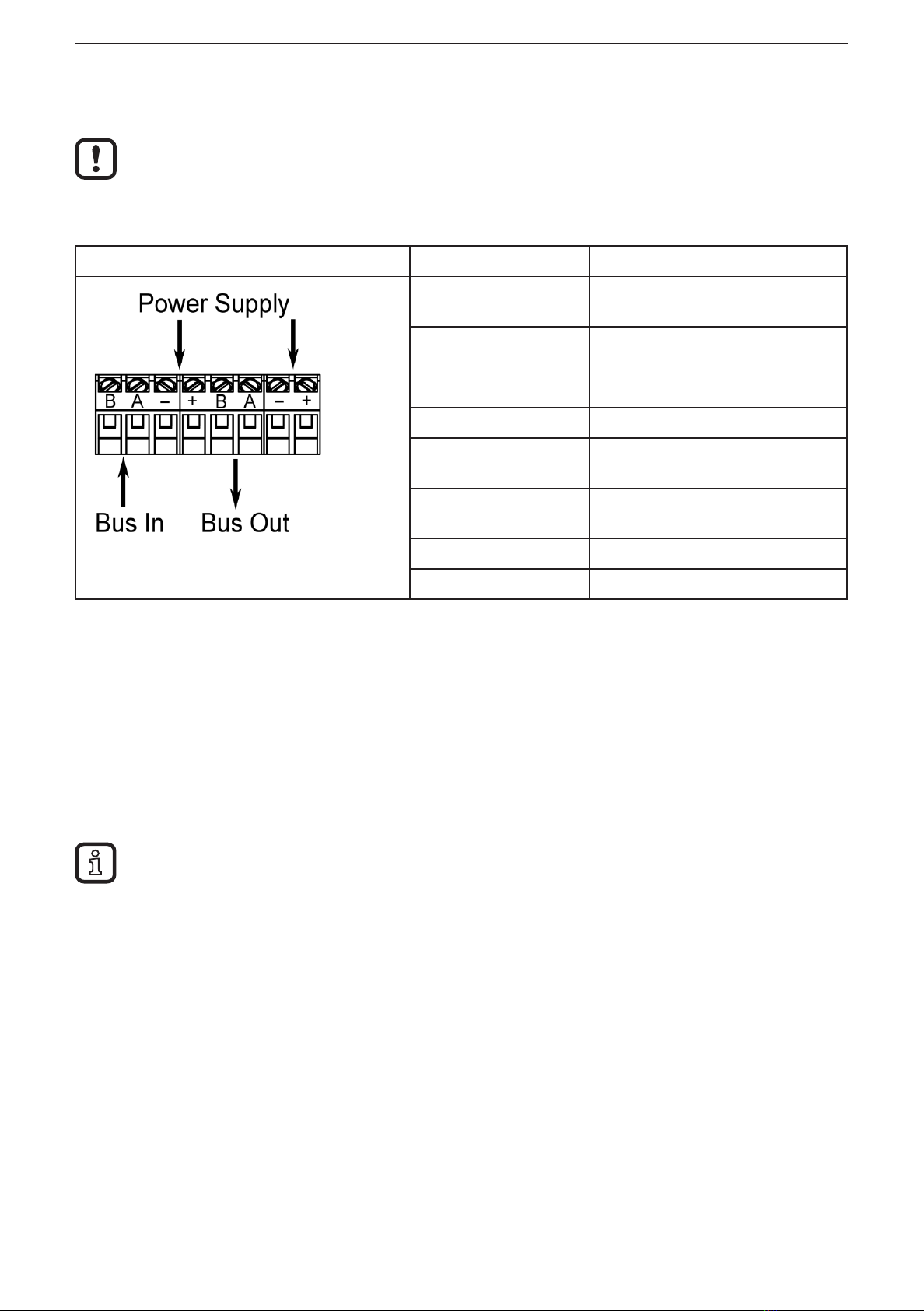
5 Electrical connection� � � � � � � � � � � � � � � � � � � � � � � � � � � � � � � � � � � � � � � � � � � � � � 6
5�1 Connection of the signal and supply cables � � � � � � � � � � � � � � � � � � � � � � � � 6
6 Installation� � � � � � � � � � � � � � � � � � � � � � � � � � � � � � � � � � � � � � � � � � � � � � � � � � � � � � 6
7 Installation� � � � � � � � � � � � � � � � � � � � � � � � � � � � � � � � � � � � � � � � � � � � � � � � � � � � � � 7
7�1 Settings in the terminal cap � � � � � � � � � � � � � � � � � � � � � � � � � � � � � � � � � � � � 7
7�1�1 Participant address � � � � � � � � � � � � � � � � � � � � � � � � � � � � � � � � � � � � � � 7
7�1�2 Bus termination � � � � � � � � � � � � � � � � � � � � � � � � � � � � � � � � � � � � � � � � � 7
8 Device configuration � � � � � � � � � � � � � � � � � � � � � � � � � � � � � � � � � � � � � � � � � � � � � � 8
9 Encoder classes � � � � � � � � � � � � � � � � � � � � � � � � � � � � � � � � � � � � � � � � � � � � � � � � � 8
9�1 Class 1 and Class 2 � � � � � � � � � � � � � � � � � � � � � � � � � � � � � � � � � � � � � � � � � � 8
9�2 Parameter setting � � � � � � � � � � � � � � � � � � � � � � � � � � � � � � � � � � � � � � � � � � � � 9
9�2�1 Class 2 functionality � � � � � � � � � � � � � � � � � � � � � � � � � � � � � � � � � � � � � � 9
9�2�2 Commissioning diagnostics � � � � � � � � � � � � � � � � � � � � � � � � � � � � � � � � 9
9�2�3 Scaling function � � � � � � � � � � � � � � � � � � � � � � � � � � � � � � � � � � � � � � � � 10
9�2�4 Measuring steps per revolution � � � � � � � � � � � � � � � � � � � � � � � � � � � � 10
9�2�5 Total resolution � � � � � � � � � � � � � � � � � � � � � � � � � � � � � � � � � � � � � � � � � 10
9�3 Data exchange during normal operation � � � � � � � � � � � � � � � � � � � � � � � � � �11
9�3�1 Transfer of the process actual value � � � � � � � � � � � � � � � � � � � � � � � � �11
9�3�2 Preset function � � � � � � � � � � � � � � � � � � � � � � � � � � � � � � � � � � � � � � � � � 12
10 Profibus encoder profile Class 2� � � � � � � � � � � � � � � � � � � � � � � � � � � � � � � � � � � 13
10�1 Parameters� � � � � � � � � � � � � � � � � � � � � � � � � � � � � � � � � � � � � � � � � � � � � � � 14
10�1�1 Activation of the manufacturer-specific parameters � � � � � � � � � � � � 14
10�1�2 Requested measuring steps � � � � � � � � � � � � � � � � � � � � � � � � � � � � � 14
10�1�3 Required resolution � � � � � � � � � � � � � � � � � � � � � � � � � � � � � � � � � � � � 15
10�1�4 Activate set-up mode � � � � � � � � � � � � � � � � � � � � � � � � � � � � � � � � � � � 16
10�1�5 Reduced diagnosis � � � � � � � � � � � � � � � � � � � � � � � � � � � � � � � � � � � � 17
10�1�6 Software limit switch� � � � � � � � � � � � � � � � � � � � � � � � � � � � � � � � � � � � 17
10�1�7 Physical measuring steps � � � � � � � � � � � � � � � � � � � � � � � � � � � � � � � 18
10�1�8 Encoder type � � � � � � � � � � � � � � � � � � � � � � � � � � � � � � � � � � � � � � � � � 18
10�1�9 Unit of measurement velocity� � � � � � � � � � � � � � � � � � � � � � � � � � � � � 19
10�2 Data exchange during normal operation � � � � � � � � � � � � � � � � � � � � � � � � 19
10�3 Set-up mode� � � � � � � � � � � � � � � � � � � � � � � � � � � � � � � � � � � � � � � � � � � � � � 20

UK
Encoder with Profibus interface
3
10�3�1 Set the direction of rotation � � � � � � � � � � � � � � � � � � � � � � � � � � � � � � 21
10�4 Start teach operation � � � � � � � � � � � � � � � � � � � � � � � � � � � � � � � � � � � � � � � 21
10�4�1 Stop teach operation � � � � � � � � � � � � � � � � � � � � � � � � � � � � � � � � � � � 21
10�4�2 Preset value � � � � � � � � � � � � � � � � � � � � � � � � � � � � � � � � � � � � � � � � � � 23
11 Diagnostic messages � � � � � � � � � � � � � � � � � � � � � � � � � � � � � � � � � � � � � � � � � � � 24
11�1 Overview� � � � � � � � � � � � � � � � � � � � � � � � � � � � � � � � � � � � � � � � � � � � � � � � � 24
11�2 Supported diagnostic messages � � � � � � � � � � � � � � � � � � � � � � � � � � � � � � 25
11�2�1 Extended diagnostic header� � � � � � � � � � � � � � � � � � � � � � � � � � � � � � 25
11�2�2 Memory error � � � � � � � � � � � � � � � � � � � � � � � � � � � � � � � � � � � � � � � � � 25
11�2�3 Operating status � � � � � � � � � � � � � � � � � � � � � � � � � � � � � � � � � � � � � � � 25
11�2�4 Encoder type � � � � � � � � � � � � � � � � � � � � � � � � � � � � � � � � � � � � � � � � � 25
11�2�5 Singleturn resolution� � � � � � � � � � � � � � � � � � � � � � � � � � � � � � � � � � � � 25
11�2�6 Number of revolutions � � � � � � � � � � � � � � � � � � � � � � � � � � � � � � � � � � 26
11�2�7 Operating time alarm � � � � � � � � � � � � � � � � � � � � � � � � � � � � � � � � � � � 26
11�2�8 Profile version� � � � � � � � � � � � � � � � � � � � � � � � � � � � � � � � � � � � � � � � � 26
11�2�9 Software version� � � � � � � � � � � � � � � � � � � � � � � � � � � � � � � � � � � � � � � 26
11�2�10 Operating time � � � � � � � � � � � � � � � � � � � � � � � � � � � � � � � � � � � � � � � 26
11�2�11 Zero point shift � � � � � � � � � � � � � � � � � � � � � � � � � � � � � � � � � � � � � � � 26
11�2�12 Configured resolution � � � � � � � � � � � � � � � � � � � � � � � � � � � � � � � � � � 26
11�2�13 Configured total resolution � � � � � � � � � � � � � � � � � � � � � � � � � � � � � � 26
11�2�14 Serial number � � � � � � � � � � � � � � � � � � � � � � � � � � � � � � � � � � � � � � � � 27
12 LED indicators � � � � � � � � � � � � � � � � � � � � � � � � � � � � � � � � � � � � � � � � � � � � � � � � 27
12�1 Legend � � � � � � � � � � � � � � � � � � � � � � � � � � � � � � � � � � � � � � � � � � � � � � � � � � 27
13 Configuring with STEP7 � � � � � � � � � � � � � � � � � � � � � � � � � � � � � � � � � � � � � � � � � 28
13�1 Installation and import of the GSD file � � � � � � � � � � � � � � � � � � � � � � � � � � 28
13�2 Adding an encoder to a STEP7 project � � � � � � � � � � � � � � � � � � � � � � � � � 30
13�3 Parameter setting � � � � � � � � � � � � � � � � � � � � � � � � � � � � � � � � � � � � � � � � � � 31

Encoder with Profibus interface
4
1 Preliminary note
1.1 Symbols used
►Instruction
> Reaction, result
[…] Designation of keys, buttons or indications
→Cross-reference
Important note
Non-compliance can result in malfunction or interference�
Information
Supplementary note
1.2 Warning signs used
NOTE
Warning of damage to property�
1.3 Notes on this document
This document applies to encoders of the following type:
RM30xx and RN30xx with Profibus interface
It is part of the device and contains information about the correct handling of the
product�
This document is intended for qualified electricians� These specialists are people
who are qualified by their training and their experience to recognise and to avoid
possible hazards that may be caused during operation of the device�
►Read this document before using the device�
►Keep this document during the service life of the device�
►Observe these operating instructions�
►Adhere to the warning notes�
2 Safety instructions
Non-observance of the instructions, operation which is not in accordance with use
as prescribed below, wrong installation or incorrect handling can affect the safety
of operators and machinery�
The installation and connection must comply with the applicable national and
international standards� Responsibility lies with the person installing the unit� Only
the signals indicated in the technical data or on the device label may be supplied
to the connections or wires�

UK
Encoder with Profibus interface
5
3 General information
3.1 1.2 Profibus technology
Profibus is a manufacturer-independent, open fieldbus standard determined by
the international standards EN 50170 and EN 50254�
There are 3 versions: DP, FMS and PA�
ifm encoders support the DP version and are designed for common baud rates
up to 12 Mbaud�
Besides manufacturer-specific functions the devices support the classes 1 and
2 to the encoder profile� This device profile can be ordered from the Profibus
user organisation indicating the order number 3�062�
Here you can also get further information about PROFIBUS (functionality,
manufacturers, products) as well as standards and profiles
→
www�profibus�
com�
4 Functions and features
The encoder converts rotary movements into digital numerical values� Each
revolution and each angular position of the revolutions is provided as a numerical
value� These values allow angular movements to be measured and positions and
number of revolutions to be determined�
Products from ifm electronic gmbh are usually individual components of larger installations� These
applications require tests of the entire installation and do not only depend on the specification of
these components� The notes in this manual apply only to the product from ifm electronic and not to
the entire installation� If the product is used in a non-intended way, this will be at your own risk�

Encoder with Profibus interface
6
5 Electrical connection
►Disconnect power�
►Connect the device according to the indications on the type label�
5.1 Connection of the signal and supply cables
Terminal Description
B (left) Signal cable B
Incoming bus cable
A (left) Signal cable A
Incoming bus cable
- 0 V
+ 10���30 V
B (right) Signal cable B
Outgoing bus cable
A (right) Signal cable A
Outgoing bus cable
- 0 V
+ 10���30 V
6 Installation
►Disconnect power�
►Ensure that the machine stands still�
►The drive must not be started during installation�
►Do not hit the shaft; do not use a file or similar tool on the shaft� Risk of
destruction!
This product is a precision measuring device� Therefore it has to be handled with care by trained
staff� The following warnings apply to influences outside the limit values indicated in the product data
sheet�
Damage to the product can be caused by:
●electrostatic discharge while touching the electronics
●too high forces on the shaft
●humidity and chemical liquids (do not connect any cables oriented upwards)
●extreme temperatures
●too high vibrations and shocks
●short circuit or too high an operating voltage
●impact, shock or any other physical forces

UK
Encoder with Profibus interface
7
7 Installation
The encoder is connected via the terminal cap� It is connected to the encoder via
a 15-pole D-Sub-connector and can be removed by loosening the 2 screws on the
back of the device� Bus and supply cables are inserted in the cab via cable glands
and connected via screw terminals�
7.1 Settings in the terminal cap
7.1.1 Participant address
The Profibus participant address is set via decimal rotary switches in the terminal
cap� The positional value (x 10 or x 1) is indicated on the switch� Possible
addresses are between 1 and 99; each address must only occur in the system
once�
The device address is read when the voltage supply of the encoder is applied; a
change of address by the master [Set_Slave_Add] is not supported�
Connection and setting of addressing
5
+- BA
1
2
3
4
5
6
7
8
9
0
1
2
3
4
5
6
7
8
9
0
+-
BA
123
4
1: Supply +UB/ - GND
2: Bus IN
3: Bus OUT
4: Addressing
5: Setting terminating resistor
7.1.2 Bus termination
If the encoder is installed as an end device, the terminal resistor integrated in the
device must be activated� This is done via the slide switch in the terminal cap (5)�

Encoder with Profibus interface
8
When the terminal resistor is activated, the next bus (Bus Out) is decoupled�
The bus is only correctly connected if the encoder is installed on the terminal cap� If the encoder has
to be replaced during operation, the use of a separate active bus termination is recommended�
After the address has been set in the hardware and, if applicable, the terminating resistor has been
activated, the encoder can be put into operation�
8 Device configuration
Encoders with Profibus interface can be configured and parameterised according
to the requirements of the user�
In this respect the GSD file of the device is loaded into the projection tool� Various
encoder classes can be selected for the projection� Parameters and functionalities
of the device that can be set depend on the selected encoder class� ifm encoders
of the RM30xx and RN30xx series support all encoder classes described below�
Therefore the functionality is not restricted from the hardware side and is only
determined by the user� ifm encoders do not only provide the encoder classes
"Class 1" and "Class 2" described in the encoder profile but also encoder classes
with manufacturer-specific functions�
When configuring the device, configuration and parameter data are defined by
selecting the encoder class� This data saved in the Profibus master is transferred
once to the encoder when the system starts up (configuration and parameterising
phase – "DDLM_Set_Prm")� It is not possible to change configuration or
parameters during operation�
After the configuration and parameter data has been received, the encoder goes
into normal operation (cyclic data exchange – "DDLM_Data_Exchange mode")
in which, for example, the position value is transferred� The length and format of
the data exchanged are also defined when configuring the device by selecting the
appropriate encoder class�
9 Encoder classes
9.1 Class 1 and Class 2
The encoder classes Class 1 and Class 2 are the versions according to the
encoder profile defined by the encoder working group in the Profibus user
organisation (available from PNO indicating order no� 3�062)�

UK
Encoder with Profibus interface
9
9.2 Parameter setting
The following table gives an overview of the parameters that can be set according
to the encoder profile and of the arrangement in the parameter setting telegram�
Parameters are set using input masks in the projection tool�
Octet (= byte) no. Parameters Bit no. Details
1���8 Profibus standard parameters
9 Direction of rotation 0 → Chapter 9.2.1
Class 2 functionality 1 → Chapter 9.2.2
Commissioning diagnostics 2 → Chapter 9.2.3
Scaling function 3 → Chapter 9.2.4
Reserved 4
Reserved 5
Not used for Class 1 and Class 2 6
7
10���13 Measuring steps / revolution → Chapter 9.2.5
14���17 Total resolution → Chapter 9.2.6
18���25 Reserved (to encoder profile)
26��� Not used for Class 1 and Class 2
Rotational direction
The direction of rotation defines the counting direction of the process actual value
output when the shaft rotates clockwise (CW) or counter-clockwise (CCW)� The
counting direction is defined by bit 0 in octet 9�
Octet 9 bit 0 Direction of rotation when viewing the shaft Direction of
rotation
0 Clockwise (CW) Rising
1 Counter-clockwise (CCW) Rising
9.2.1 Class 2 functionality
Class 2 encoders can be limited to the functionality of Class 1; the possibility of
parameter setting is disabled� To use the function of Class 2 encoders, bit 1 is set
in octet 9�
Octet 9 bit 1 Class 2 functionality
0 Disabled
1 Enabled
9.2.2 Commissioning diagnostics
This function is of no meaning for the ifm encoder�

Encoder with Profibus interface
10
9.2.3 Scaling function
The scaling function enables parameter setting of the resolution per revolution and
the selected total resolution� It should always be enabled if you want to use the
functions of Class 2 (or the manufacturer-specific classes)�
Octet 9 bit 3 Scaling function
0 Disabled
1 Enabled
9.2.4 Measuring steps per revolution
This parameter is used to assign a requested number of steps referred to one
revolution to the encoder�
If the value of the parameter exceeds the actual physical basic resolution of the
encoder, the output value no longer proceeds by one step�
For encoders as of the B1 generation a parameter fault is displayed in this case;
the device does not change to the cyclic data transfer�
For high-resolution encoders it may be required to split the value into high word
and low word, depending on the projection tool�
Octet 10 11 12 13
Bit 31���24 23���16 15���8 7���0
Data 231 to 224 223 to 216 215 to 2827to 20
Requested number of measuring steps per revolution
9.2.5 Total resolution
Octet 14 15 16 17
Bit 31���24 23���16 15���8 7���0
Data 231 to 224 223 to 216 215 to 2827to 20
Selected total resolution in measuring steps
This parameter enables the user to adapt the measuring range of the device� The
encoder counts up to the configured total resolution and then it starts again at 0�
Example
Selected: 100 steps per revolution, total resolution 12800, then the encoder starts
again at zero after 128 revolutions and counts again up to 12799�
With many projection tools it may be required to split the value into high word and
low word�

UK
Encoder with Profibus interface
11
When the [Total measuring range] parameter is entered, use the following formula:
total resolution < measuring steps per revolution x number of revolutions
(physical)
If this is not observed, the device indicates a parameter fault and does not go into the cyclic data
exchange�
The internal software routine is only effective during operation�
9.3 Data exchange during normal operation
The DDLM_Data_Exchange mode is the normal status during system operation�
On request, the encoder sends current position values to the master� Conversely,
the encoder can also receive cyclic data (e�g� the preset value with Class 2
encoders)�
9.3.1 Transfer of the process actual value
The current position value of the multiturn encoder is transferred as a 32-bit value
(double word) to the master�
Word Word 1 Word 0
Function Process actual value
Bit 31���30 29���16 15���0
0 X X

Encoder with Profibus interface
12
9.3.2 Preset function
The preset function enables adaptation of the encoder zero point to the
mechanical zero point of the system�
►Set the encoder actual value to the requested preset value�
> The requested zero point drift is calculated by the device and stored in an
EEPROM (non-volatile) which takes less than 40 ms�
The preset value is activated in the peripheral output double word by setting bit
31 (adopted with rising edge)� Setting is made automatically after transfer of the
scaling parameters, i�e� the preset value refers to the scaled actual value�
Data bits
Bit 4 31 30 29...0
Master → encoder 1 0 Transfer of the requested value
(= preset value)
Encoder → master 0 0 New = requested process actual value is transferred
Master → encoder 0 0 Reset bit 31 - normal mode
Encoder → master 0 0 New = requested process actual value is transferred
Only set the preset while the encoder shaft is at standstill� If the shaft moves
during this time, shifts are possible since runtimes occur via the bus when the
preset value is set�
Note on the singleturn version
The process can be transferred to the singleturn version – here bit 15 is used to
activate the preset value� With high-resolution singleturn encoders (16 bits) no
preset values > 32767 (15 bits) can be set in Class 2 (MSB is used to activate the
preset value)� If this function is requested, one of the manufacturer-specific ifm
classes has to be selected (transfer here also in 32-bit format for the singleturn)�

UK
Encoder with Profibus interface
13
10 Profibus encoder profile Class 2
Parameter setting telegram
Octet (= byte) no. Parameters Bit no. Details
1���8 Profibus standard parameter
9 Direction of rotation 0 → Chapter 9.2.1
Class 2 functionality 1 → Chapter 9.2.2
Commissioning diagnostics 2 → Chapter 9.2.3
Scaling function 3 → Chapter 9.2.4
Reserved 4
Reserved 5
Activate manufacturer-specific
parameters (octet 26)
6→ Chapter 10.1.1
Reserved 7
10���13 Measuring steps / revolution
(Reference: octet 26 bits 0 and 1)
→ Chapter 10.1.2
14���17 Total resolution → Chapter 9.2.6
18���25 Reserved
26 Reference to the requested
measuring steps
0
1
→ Chapter 10.1.3
Activate set-up mode 2 → Chapter 10.1.4
Reduced diagnosis 3 → Chapter 10.1.5
Reserved 4
Activate lower software limit switch 5 → Chapter 10.1.6
Activate upper software limit switch 6 → Chapter 10.1.6
Activate parameters as from octet
27
7→ Chapter 10.1.1
27���30 Lower limit switch → Chapter 10.1.6
31���34 Upper limit switch → Chapter 10.1.6
35���38 Physical measuring steps → Chapter 10.1.7
39 Reserved 0
Encoder (singleturn or multiturn) 1 → Chapter 10.1.8
Reserved 2
Reserved 3
Selection of the measuring unit to
provide the value of velocity
4
5
→ Chapter 10.1.9
Reserved 6
Reserved 7

Encoder with Profibus interface
14
10.1 Parameters
The manufacturer-specific parameters are described below� The parameters to the
encoder profile (also supported) are described in chapter 9�
10.1.1 Activation of the manufacturer-specic parameters
The manufacturer-specific parameter byte 26 is activated via bit 6 in octet 9�
The manufacturer-specific bytes 27���39 are activated in byte 26�
Octet 9 bit 6 Octet 26
0 Deactivated
1 Activated
Octet 26 bit 7 Octet 27...29
0 Deactivated
1 Activated
10.1.2 Requested measuring steps
The device can be programmed with the [Desired measuring units] parameter so
that any number of measuring steps referred to
– one revolution
– the entire measuring range
– any part of the measuring range
can be implemented�
Octet 10 11 12 13
Bit 31���24 23���16 15���8 7���0
Data 231 to 224 223 to 216 215 to 2827to 20
Required number of measuring steps

UK
Encoder with Profibus interface
15
10.1.3 Required resolution
Parameter selection of
– resolution per revolution
– or max� total resolution
– code sequence
– Class 2 functionality
– scaling function
Selection required resolution
Resolution per revolution
The position value is scaled so that it increases by the number of the required
measuring steps during one revolution�
In addition the [Total mesuring range] parameter is evaluated via which the
measuring range can be adapted (→ chapter 9.2.5)
Resolution per max� total resolution
The requested measuring steps entered refer to the total measuring range�
The device provides the configured number of measuring steps via the total
(physical) number of revolutions�

Encoder with Profibus interface
16
Resolution per physical measuring steps
The requested number of steps refers to the data entered via the [Physical
impulses] parameter (→ chapter 10.1.7).
This is the numerical value that is read from the coded disc inside the encoder
(e�g� 4096 steps per revolution for the standard 12-bit version)�
This option allows free setting of gearbox factors�
Reference Octet 26 bit 0 Octet 26 bit 1
Per revolution 0 0
Per max� total resolution 1 0
Per physical measuring steps
(= steps indicated in octets 35-38)
0 1
10.1.4 Activate set-up mode
Bit 2 in octet 26 is a switch for the set-up mode�
In this mode other parameters besides the preset value can be transferred to the
encoder�
With activated mode a teach operation can be carried out; the gearbox factor can
be directly determined in the system�
In this mode (green LED flashing) the direction of rotation and scaling set during
projection are ignored and the values saved in the internal EEPROM are used�
The device can be operated permanently in the set-up mode�
Recommendation:
Transfer the parameters determined in the set-up mode and then use the device in
normal mode (which enables a replacement of the device without having to repeat
the teach operation)�
Octet 26 bit 2 Set-up mode
0Off
1 On

UK
Encoder with Profibus interface
17
10.1.5 Reduced diagnosis
With older Profibus masters the full number of diagnostic bytes (standard
diagnosis: 57 bytes) may lead to problems� �
With the RM30xx and RN30xx devices it is possible to reduce the number of the
diagnostic bytes provided by the encoder to 16� If the device class "Class 1" is
selected, only 16 diagnostic bytes are provided in general�
Octet 26 bit 3 Diagnostic data length
0 Standard = 57 bytes
1 Reduced = 16 bytes
10.1.6 Software limit switch
2 positions can be programmed� If they are exceeded or not reached, the encoder
sets bit 27 in the 31-bit process actual value to "1"�
Between the two positions the bit is set to "0"� Both limit switch values can be set
to any value via parameter setting but they must not exceed the value of the [Total
measuring range] parameter� The limit switches are activated via bit 5 or 6 in octet
26�
With many projection tools it may be required to split the values into high word and low word�
Octet 27 28 29 30 31 32 33 34
Bit 31���24 23���16 15���8 7���0 31���24 23���16 15���8 7���0
Data 231���224 223���216 215���2827���20231���224 223���216 215���2827���20
Lower limit switch in measuring steps (referred to scaled value)
Octet 26 bit 5 Lower limit switch
0Off
1 On
Octet 26 bit 6 Upper limit switch
0Off
1 On

Encoder with Profibus interface
18
10.1.7 Physical measuring steps
Octet 35 36 37 38
Bit 31���24 23���16 15���8 7���0
Data 231���224 223���216 215���2827���20
Physical measuring steps
This parameter is evaluated by the device if the option [Physical impulses] was
selected as reference to the requested measuring steps� By means of the physical
measuring steps a gearbox factor can be freely set� Here it is defined how many
measuring steps (requested measuring steps) are to be provided on a defined
sub-measuring range� This option is useful if "odd" scaling factors are to be
entered�
Example
The encoder is to provide 400 steps over 3 revolutions�
With the reference [Desired measuring units per revolution] this number of steps
cannot be set (the [Desired measuring units] parameter should contain the value
133�333; however only integers can be entered)�
Remedy
The physical measuring steps are selected as reference for the requested
measuring steps�
The number of the physical measuring steps over the requested measuring range
is determined on the basis of the actual (physical) resolution of the device (type
label)� For this absolute encoder with 12-bit standard resolution this would in this
case be
4096 steps/revolution x 3 revolutions = 12288 steps
This value is now entered as [Physical impulses] parameter; the actually required
number of steps of 400 is entered at [Desired measuring units]� The encoder
now provides 400 steps over a measuring range of 12288 physical steps (i�e� 3
revolutions)�
Note: With many projection tools it may be required to split the value into high
word and low word�
10.1.8 Encoder type
The type of encoder (singleturn or multiturn) is defined in bit 1 of octet 39� This
is done automatically when the encoder class is selected� The user only has to
consider this parameter if parameters are set directly in the hexadecimal code�
Octet 39 bit 1 Type
0 Singleturn
1 Multiturn

UK
Encoder with Profibus interface
19
10.1.9 Unit of measurement velocity
The unit for the velocity value to be provided (class ifm 2�2) can be set via this
parameter�
Unit Bit 4 Bit 5
Steps / second 0 0
Steps / 100ms 1 0
Steps/10ms 0 1
Revolutions / minute 1 1
10.2 Data exchange during normal operation
The process actual value is in general transferred as a 32-bit word (double word)
with the manufacturer-specific encoder classes ifm 2�1 and ifm 2�2� In addition to
the 25 bits that are provided for the position value 7 other bits are used as status
bits� In the (peripheral) output double word the master sends the preset value and
in addition the control bits to the encoder�
For encoders of this type more than 25-bit absolute position data may be available�
The position values < 25 bits are not supported in the ifm classes; the more
significant bits are overwritten by status bits�
If the ifm classes are to be used with encoders whose physical resolution exceeds
25 bits, the user must ensure that the physical position value is scaled to a (max�)
output value < 33554432 (via parameter setting)� If absolute values > 25 bits are
required, Class 2 has to be selected�
An additional (peripheral) input word of the current velocity value is transferred
with device class ifm 2�2�
Identifica-
tion
F1 hex D0 hex
Encoder →
master
Status + position actual value Velocity
Status + 224 223 - 216 215 - 2827- 20215 - 2827- 20
Master →
encoder
Preset value + control bits
Control + 224 223 - 216 215 - 2827- 20

Encoder with Profibus interface
20
The status bits in the input double word have the following meaning
Bit Meaning
28 Rotational direction 0 = increasing clockwise
(seen on the shaft)
1 = increasing counter-clockwise
(seen on the shaft)
27 Software
Limit switch
0 = lower limit switch ≤ actual
value ≤ upper limit switch
1 = actual value > upper limit
switch or actual value < lower
limit switch
26 Operating mode 0 = set-up mode 1 = normal mode
25 Readiness for operation 0 = encoder not ready for
operation
1 = encoder ready for operation
10.3 Set-up mode
If the encoder is switched to the set-up mode via parameter setting, the gearbox
factors can be determined directly in the system via a teach operation�
The set-up mode is signalled by the encoder via a flashing green LED in the
terminal cap and via bit 26 in the input double word (set to 0)�
In the set-up mode the parameters set during projection (direction of rotation,
scaling) are ignored and the values saved in the internal EEPROM are used� If the
direction of rotation and gearbox factor are changed during the set-up mode, the
new values are stored in the EEPROM�
Process during the set-up mode
►Install the device in the system�
►Enable the set-up mode via parameter setting�
►Adapt the direction of rotation (if required)�
►Move the system to the starting position�
►Transmit the start command for the teach operation to the encoder�
►Move the system to the end position�
►Transfer the requested number of steps to the encoder with the "stop teach
operation" command�
►Set the preset value�
►Transfer the values determined during the teach operation to the projection
(parameters)�
►Disable the set-up mode during parameter setting�
This manual suits for next models
1
Table of contents
Other IFM Electronic Media Converter manuals

IFM Electronic
IFM Electronic AS-i CompactLineM12 User manual

IFM Electronic
IFM Electronic Efector 400 RA Series User manual

IFM Electronic
IFM Electronic Efector 400 User manual

IFM Electronic
IFM Electronic Efector 400 RO Series User manual

IFM Electronic
IFM Electronic Efector 400 RM30 Series Application guide

IFM Electronic
IFM Electronic E7354A User manual

IFM Electronic
IFM Electronic Efector 400 RV User manual

IFM Electronic
IFM Electronic E70454 User manual