Optical Systems Design OSD2139 Series User manual

OPERATOR MANUAL
OSD2139 SERIES
UNMANAGED 2-PORT MEDIA
CONVERTER WITH
2 DUPLEX DATA & CONTACT CLOSURE
CHANNELS


OPTICAL SYSTEMS DESIGN
DOC ID: 10118201
OSD2139 OPERATOR MANUAL
PAGE 3
INDEX 1
1TECHNICAL SUMMARY........................................................................................................4
1.1 BRIEF DESCRIPTION............................................................................................................4
1.1.1 OVERVIEW............................................................................................................................................. 4
1.1.2 APPLICATIONS...................................................................................................................................... 4
1.1.3 FEATURES AND BENEFITS................................................................................................................. 4
1.2 OSD2139 CONFIGURATION.................................................................................................5
1.2.1 OSD2139 UNIT ....................................................................................................................................... 5
1.2.2 TYPICAL CONFIGURATION ............................................................................................................... 5
1.3 TECHNICAL SPECIFICATIONS ...........................................................................................6
1.4 OSD2139 FRONT AND REAR PANELS................................................................................7
2INSTALLATION AND OPERATION.....................................................................................8
2.1 INTRODUCTION....................................................................................................................8
2.2 INSTALLATION .....................................................................................................................8
2.2.1 WARNING AND PRECAUTIONS......................................................................................................... 8
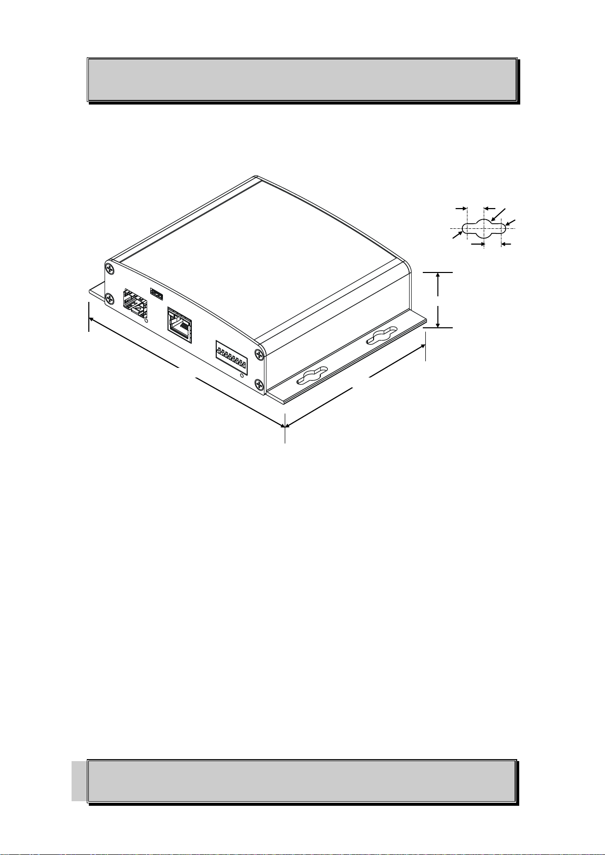
2.2.2 OSD2139 DRAWINGS AND DIMENSIONS......................................................................................... 9
2.2.3 POWER SUPPLY CONNECTIONS ..................................................................................................... 10
2.2.4 RJ45 COPPER PIN ASSIGNMENTS.................................................................................................... 10
2.2.5 CONTACT CLOSURE I/O.................................................................................................................... 11
2.2.6 MICRO USB CONNECTOR................................................................................................................. 12
2.2.7 MINI USB CONNECTOR..................................................................................................................... 12
2.2.8 PORT ALLOCATION AND LED INDICATORS................................................................................ 13
2.2.9 CONTROLS........................................................................................................................................... 14
2.2.10 FITTING SFP CONNECTORS......................................................................................................... 15
2.3 OSD2139 CONNECTIONS ................................................................................................... 16
3MAINTENANCE......................................................................................................................17
3.1 INTRODUCTION.................................................................................................................. 17
3.2 EXTERNAL INSPECTION................................................................................................... 17
3.3 ROUTINE MAINTENANCE................................................................................................. 17
4WARRANTY............................................................................................................................ 18
4.1 WARRANTY PERIOD..........................................................................................................18
4.2 REPAIRS................................................................................................................................ 18
4.2.1 WARRANTY REPAIRS........................................................................................................................ 18
4.2.2 OUT-OF-WARRANTY REPAIRS........................................................................................................ 18
4.2.3 SITE REPAIRS...................................................................................................................................... 18
4.2.4 EXCLUSIONS....................................................................................................................................... 18
FIGURE 1: OSD2139 UNIT.................................................................................................................... 5
FIGURE 2: OSD2139 TYPICAL POINT-POINT CONFIGURATION..................................................5
FIGURE 3: OSD2139 FRONT AND REAR PANELS ...........................................................................7
FIGURE 4: OSD2139 MOUNTING DIMENSIONS...............................................................................9
FIGURE 5: OSD2139 POWER SUPPLY CONNECTION...................................................................10
FIGURE 6: 10/100/1000BASE-T ETHERNET RJ45 CONNECTOR................................................... 10
FIGURE 7: DATA AND CONTACT CLOSURE CONNECTIONS....................................................11
FIGURE 8: CONTACT CLOSURE INPUT AND OUTPUT................................................................ 12
FIGURE 9: USB TYPE B PORT........................................................................................................... 12
FIGURE 10: OSD2139 USB CONNECTOR......................................................................................... 12
FIGURE 11: PORT/LED........................................................................................................................ 13
FIGURE 12: OSD2139 8-WAY DIP SWITCH ..................................................................................... 14
FIGURE 14: FITTING/REMOVING SFP CONNECTORS .................................................................15
TABLE 1: TECHNICAL SPECIFICATIONS.........................................................................................6
TABLE 2: DC POWER CONNECTION............................................................................................... 10
TABLE 3: DATA AND CONTACT CLOSURE CONNECTIONS...................................................... 11
TABLE 4: LED FUNCTION ................................................................................................................. 13
TABLE 5: OSD2139 8-WAY DIP SWITCH SETTINGS.....................................................................14
TABLE 6: OSD2139 SERIAL DATA SPEED SETTINGS ..................................................................14

OPTICAL SYSTEMS DESIGN
DOC ID: 10118201
OSD2139 OPERATOR MANUAL
PAGE 4
1TECHNICAL SUMMARY
1.1 BRIEF DESCRIPTION
1.1.1 OVERVIEW
The OSD2139 is an unmanaged 2-port media converter supplied in standaline module format with 2
duplex data channels and 2 duplex contact closure channels. It has one 10/100/1000Base-T RJ45
copper port and one SFP port which can be specified by the user for 100Base-Fx/1000Base-Lx/Sx fiber
mode or as 10/100/1000Base-T RJ45 copper.
The unit will operate on either singlemode or multimode fiber. Operation over at least 50km of
singlemode fiber is possible by use of the appropriate SFP optical devices. It normally requires two
fibers but is optionally available for one fiber operation.
A major benefit of the OSD2139 is its reliable and consistent performance over the -20°C to +75°C
temperature range that allows it to be used in uncontrolled environments such as roadside cabinets,
mine sites and factories.
1.1.2 APPLICATIONS
▲Any network utilising a mix of copper
and fiber
▲Industrial IP communications
▲Gigabit backbone networks
▲IP cameras with tamper alarms and/or
washer/wiper controls
1.1.3 FEATURES AND BENEFITS
▲Complies with IEEE802.3i/802.3u/
802.3ab 10/100/1000Base-T,
IEEE802.3u 100Base-Fx, IEEE802.3z
1000Base-Lx/Sx standards.
▲Has a total of two ports: one fixed
copper port for 10/100/1000Base-T
and one SFP port which may be either
copper or fiber
▲Supports network traffic of
1000Mbps
▲Can be used with either singlemode
or multimode fiber over a variety of
link budgets
▲Available for operation over 1 or 2
fibers
▲Automatic TP setup: no need for
crossover cables
▲Auto TP sensing of half or full duplex
operation in 10/100 mode
▲Powered by non critical 12VDC or
24VAC supplies
▲Operates over the temperature range
of -20°C to +75°C
▲Duplex transmission of two alarm
signals and two data signals
▲One data signal can be RS422 or 2-
wire /4-wire RS485 and the other is
RS232
▲SFP module sold separately

OPTICAL SYSTEMS DESIGN
DOC ID: 10118201
OSD2139 OPERATOR MANUAL
PAGE 6
1.3 TECHNICAL SPECIFICATIONS
TABLE 1: TECHNICAL SPECIFICATIONS
SPECIFICATION
PERFORMANCE
Electrical Data Interface
IEEE802.3i/802.3u/802.3ab, 10/100/1000Base-T Ethernet
Electrical Data Connector
RJ45 for fixed copper ports (Ports 1 and 2) and for copper SFP module
Port 1 Data Rates
10, 100, 1000Mbps with energy detect, auto negotiate, auto MDIX
Operating Mode
Half or full duplex for 10/100
Full duplex for 1000
Pause frames for flow control
Data Transmission
RS232 on Channel 1, RS422 or RS485 on Channel 2
Contact Closure Transmission
Buffered input, optically isolated MOSFET output (120mA @350V(max))
Data/Alarm Connector
Female DB15
Optical Port Connector
SFP
Various SFP Options Possible
Short haul, long haul, single fiber operation, etc.
Please consult OSD DATASHEET #1002100006 or contact OSD
Indicators
1x Power
1x Copper Speed/Activity/Link on RJ45
1x Copper Duplex on RJ45
1x SFP Speed/Activity/Link for copper or fiber
Dimensions (mm)
114W x 105D x 32H (module)
Weight
0.5kg
Power Requirements
+8V to +35VDC @ 8VA (with 1 SFP loaded)
Power Connector
2-way terminal block
Operating Temperature
-20C to +75C
Relative Humidity
0 to 95% non-condensing

OPTICAL SYSTEMS DESIGN
DOC ID: 10118201
OSD2139 OPERATOR MANUAL
PAGE 7
1.4 OSD2139 FRONT AND REAR PANELS
There is one fixed RJ45 copper port for 10/100/1000Base-T and one SFP port, a micro USB
programming port and an 8-way DIP-switch on the front panel. The rear panel has a female DB15
connector for the two data channels and two contact closure channels, a mini USB as a console port
and a 2-way terminal block power connector.
FIGURE 3: OSD2139 FRONT AND REAR PANELS
Power Connector
Mini-USB CLI Port
DB15 Data/CC Connector
SFP Port
Micro USB Programming
Port
8-Way DIP Switch
RJ45 Port

OPTICAL SYSTEMS DESIGN
DOC ID: 10118201
OSD2139 OPERATOR MANUAL
PAGE 8
2INSTALLATION AND OPERATION
2.1 INTRODUCTION
This section outlines the methods required to install and operate the OSD2139 successfully. It should be
studied carefully if damage to the equipment or poor results are to be avoided.
This equipment has been fully tested prior to dispatch and is ready for immediate operation. However it
is advisable to check for external transportation damage before operation. If damage is evident, return
the unit with the packaging to your supplier immediately.
2.2 INSTALLATION
2.2.1 WARNING AND PRECAUTIONS
▲ELECTROMAGNETIC COMPATIBILITY
WARNING: This is a Class A product. In a domestic environment this product may cause radio
interference in which case the user may be required to take adequate measures.
▲OPTICAL OUTPUT OPERATION
WARNING: Laser Safety: Class 1 Laser Product per IEC/EN 60825-1:20011 standard.
Class 1
The OSD2139 is a Class 1 laser product.
PRECAUTIONS
▲All service personnel should be provided training as to the hazards of direct viewing of laser
radiation and of the precautionary measures during servicing of equipment
▲Areas where laser products are installed should be restricted in access to trained service
personnel only and appropriate warning signs posted in the work area.
▲All laser apertures should be covered by protective covers when not connected to optical
fibers. Never leave outputs uncovered.
▲Laser equipment should be positioned above or below eye level where possible. Apertures
should be positioned away from personnel.
▲Protective eyewear should be worn in the vicinity of laser equipment.

OPTICAL SYSTEMS DESIGN
DOC ID: 10118201
OSD2139 OPERATOR MANUAL
PAGE 9
2.2.2 OSD2139 DRAWINGS AND DIMENSIONS
The OSD2139 standalone module is designed to be mounted on an even surface and to be secured by
means of M4 or smaller screws.
FIGURE 4: OSD2139 MOUNTING DIMENSIONS
R2.1
R2.1
Ø8.5
8.0
8.0
DETAIL A
114
138.4
32

OPTICAL SYSTEMS DESIGN
DOC ID: 10118201
OSD2139 OPERATOR MANUAL
PAGE 10
2.2.3 POWER SUPPLY CONNECTIONS
The OSD2139 module requires external 8 to 35VDC @ 8VA. Power should be connected to the power
socket located at the back of the case as indicated in Table 2.
TABLE 2: DC POWER CONNECTION
External Power Pin
Specification
Pin 1
+8VDC to +35VDC @ 8VA
Pin 2
Ground –0V
FIGURE 5: OSD2139 POWER SUPPLY CONNECTION
2.2.4 RJ45 COPPER PIN ASSIGNMENTS
Figure 6 shows the pin configuration for the fixed RJ45 copper port.
FIGURE 6: 10/100/1000BASE-T ETHERNET RJ45 CONNECTOR
Green LED
Bi-colour LED
8 7 6 5 4 3 2 1
Fixed Copper Port
Pin
No
10Base-T
100Base-T
1000Base-T
1
Tx+
BI_DA+
2
Tx-
BI_DA-
3
Rx-
BI_DB+
4
Unused
BI_DC+
5
Unused
BI_DC-
6
Rx-
BI_DB-
7
Unused
BI_DD+
8
Unused
BI_DD-

OPTICAL SYSTEMS DESIGN
DOC ID: 10118201
OSD2139 OPERATOR MANUAL
PAGE 11
2.2.5 CONTACT CLOSURE I/O
The OSD2139 has 2 duplex contact closure channels located on the rear panel via a 15-way DB15
connector. The contact closure inputs (Ch1 Pin2: Ch2 Pin10) is pulled high by an internal 10K resistor.
To operate the contact closure, the input should be switched to ground (see Figure 8). The contact
closure normally open output (CH1 Pin5: Ch2 Pin8) while the common contact is connected to Ch1
Pin12: Ch2 Pin14 of the DB15. Maximum ratings the OSD2139 relay can drive is 120mA @ 350V(max).
Pins 3, 7 and 8 are connected to Ground.
FIGURE 7: DATA AND CONTACT CLOSURE CONNECTIONS
TABLE 3: DATA AND CONTACT CLOSURE CONNECTIONS
Channel
Pin No
Description
Contact Closure CH1
2
CC Input
5
Normally Open Output
12
Common Output
3
Ground
Contact Closure CH2
10
CC Input
8
Normally Open Output
14
Common Output
7
Ground
RS232 CH
15
RS232 Input to OSD2139
6
RS232 Output from OSD2139
RS422/RS485 CH
1
Data + Input to OSD2139
9
Data - Input to oSD2139
4
Data + I/O to/from OSD2139
11
Data - I/O to/from OSD2139
13
Ground
Data/Contact Closure I/O

OPTICAL SYSTEMS DESIGN
DOC ID: 10118201
OSD2139 OPERATOR MANUAL
PAGE 12
OSD2139 INPUT OSD2139 OUTPUT
FIGURE 8: CONTACT CLOSURE INPUT AND OUTPUT
2.2.6 MICRO USB CONNECTOR
All OSD2139 units are shipped with the latest firmware already installed. The Micro USB port located
on the front panel is used by the manufacturer for uploading firmware and is not used by the end user.
.
FIGURE 9: OSD2139 MICRO USB PORT
2.2.7 MINI USB CONNECTOR
The Mini USB connector located on the rear panel can be used for a command line interface (CLI).
Please contact OSD for full details.
FIGURE 10: OSD2139 MINI USB CONNECTOR
3V
Ch 1:Pin2
Ch2: Pin10
OSD2139
4K7
External
Switch
3V
33K
Ch1: Pin12
Ch2: Pin14
OSD2139
Ch1: Pin5
Ch2: Pin8
Micro USB - CLI
Mini USB Port - CLI

OPTICAL SYSTEMS DESIGN
DOC ID: 10118201
OSD2139 OPERATOR MANUAL
PAGE 13
2.2.8 PORT ALLOCATION AND LED INDICATORS
FIGURE 11: PORT/LED
TABLE 4: LED FUNCTION
No
LED Colour Function
Green
Amber
Off
Blinking
Port 1 Fiber
Link 1Gbps
Port 1 Fiber Link
100Mbps
No Fiber Link
N/A
Port 2 1Gbps
Port 2 10/100Mbps
N/A
N/A
N/A
Port 2 Link OK
No Copper Link
Activity
Power On
-
N/A
N/A
Speed / Status
Link / Act
Power
Link/100/1000

OPTICAL SYSTEMS DESIGN
DOC ID: 10118201
OSD2139 OPERATOR MANUAL
PAGE 14
2.2.9 CONTROLS
The OSD2139 has an 8-way DIP switch on the front panel to control a number of functions. Table 5
outlines the function of each switch.
FIGURE 12: OSD2139 8-WAY DIP SWITCH
TABLE 5: OSD2139 8-WAY DIP SWITCH SETTINGS
SWITCH
NUMBER
DESCRIPTION
FUNCTION
SWITCH POSITION
1
Fiber Speed
1000Mbps
100Mbps
OFF*
ON
2
RS422/485
RS422
RS485
OFF*
ON
3
2-Wire/4-Wire
4-Wire
2-Wire
OFF*
ON
4, 5, 6
Data Speed Setting
See Table 6 below
7
Link Loss Forwarding
LLF Disabled
LLF Enabled
OFF*
ON
8
Not Used
Not Used
OFF*
* Default settings. Firmware update switch should remain in OFF position.
TABLE 6: OSD2139 SERIAL DATA SPEED SETTINGS
Switch
Number
DC to
10kbps
2.4kbps
4.8kbps
9.6kbps
19.2kbps
38.4kbps
57.6kbps
115.2kbps
4
0
0
0
0
1
1
1
1
5
0
0
1
1
0
0
1
1
6
0
1
0
1
0
1
0
1
Up Position
Down Position
Fiber Speed 100/1000
RS422/485
2-Wire/4-Wire
Data Speed Setting 1
Data Speed Setting 2
Data Speed Setting 3
Link Loss Forwarding
Not Used
1 2 3 4 5 6 7 8

OPTICAL SYSTEMS DESIGN
DOC ID: 10118201
OSD2139 OPERATOR MANUAL
PAGE 15
2.2.10 FITTING SFP CONNECTORS
Care should be taken when inserting/removing the SFP connectors from SFP port 3,4 and 5 as SFP
modules are Electrostatic (ES) sensitive and Electrostatic Discharge (ESD) precautions should be taken
when installing. Ensure that the SFP is fully engaged and latched into position.
Inserting SFP –Ensure that the SFP lever is in the locked position and insert into appropriate SFP
port. Gently push the SFP until it locks into place. Remove plastic/rubber dust cap and fit fiber cable or
RJ45 plug.
Removing SFP –Remove fiber connector or RJ45 plug. Pull the SFP lever down to unlock SFP from
housing. Using the lever, gently pull the SFP out.
Fiber SFP
Copper SFP
FIGURE 13: FITTING/REMOVING SFP CONNECTORS
Inserting
SFP
Removing
SFP
1
2
Inserting
SFP
Removing
SFP
1
2

OPTICAL SYSTEMS DESIGN
DOC ID: 10118201
OSD2139 OPERATOR MANUAL
PAGE 16
2.3 OSD2139 CONNECTIONS
When using the OSD2139 for the first time, check that the unit is in good condition with no visible
damage.
Connect the unit to an appropriate power source and check that the indicators illuminate accordingly on
power up (see Table 4).
For RJ45 connection use Category 5 (CAT5) or higher. Length should be no more than 100 meters.
For singlemode fiber connections, fiber used must be 9/125μm singlemode fiber.
For multimode fiber connections, fiber used must be 50 or 62/ 125μm multimode fiber.
Plug in the appropriate connectors for system configuration;
–RJ45 cable to fixed copper port and copper SFP module (if used)
–LC fiber cable to fiber SFP modules.
–Male DB15 connector for the 2 contact closur and 2 data channels (supplied)
–5.08mm 2 way terminal block for power connection (supplied)

OPTICAL SYSTEMS DESIGN
DOC ID: 10118201
OSD2139 OPERATOR MANUAL
PAGE 17
3MAINTENANCE
3.1 INTRODUCTION
The following section outlines the fault-finding procedure for the OSD2139 modems. Please take note
of the following:
▲Personnel without appropriate training should not attempt any maintenance except that outlined
below.
▲If further maintenance is attempted you are warned that every care should be taken to ensure that
internal measurements made while the equipment is operational are taken carefully as some
components within the unit are expensive and may be damaged by failure of any portion of their
support circuitry.
▲Some components within the unit are Electrostatic (ES) sensitive and Electrostatic Discharge
(ESD) precautions should be taken when performing maintenance upon the unit.
3.2 EXTERNAL INSPECTION
Visually check for the following:
▲Check that the correct power source is connected to the power socket.
▲Check that the Ethernet cables are connected to the modem correctly and that the distant OSD2139
modem has been connected correctly to any external equipment.
▲Inspect the optical connectors (for fiber SFP option) for any contamination and clean using
isopropyl alcohol and a lint free tissue if any contamination is detected.
3.3 ROUTINE MAINTENANCE
▲There is no routine maintenance required with the OSD2139.

OPTICAL SYSTEMS DESIGN
DOC ID: 10118201
OSD2139 OPERATOR MANUAL
PAGE 18
4WARRANTY
Thank you for purchasing equipment designed, manufactured and serviced by Optical Systems Design
(OSD). OSD warrants that at the time of shipment, its products are free from defects in material and
workmanship and conforms to specifications. Our Warranty conditions are outlined below:
4.1 WARRANTY PERIOD
For warranty period, please contact your local OSD distributor.
4.2 REPAIRS
Optical Systems Design reserves the right to repair or replace faulty modules/units. Please obtain a
“Return Material Authorisation” (RMA) form and number before returning goods.
Goods must be returned in adequate packing material to Optical Systems Design, Warriewood or its
nominated authorised representative, for all repairs.
4.2.1 WARRANTY REPAIRS
Return shipments to OSD shall be at customer's expense and freight back to the customer will be at
OSD expense.
4.2.2 OUT-OF-WARRANTY REPAIRS
OSD reserves the right to repair or replace any faulty goods. Freight costs and insurance for both
journeys are met by the user. All equipment repaired by OSD will have a 3-Month Warranty from the
date of dispatch.
4.2.3 SITE REPAIRS
By agreement site repairs may be undertaken for which out of pocket, hotel and travel expenses will be
charged.
4.2.4 EXCLUSIONS
This warranty does not apply to defects caused by unauthorized modifications, misuse, abuse or
transport damage to the equipment. All modifications to OSD’s standard product will need written
authorization and will be charged at normal repair rates. All modifications are to be carried out by OSD
Technicians. Warranty is void if unauthorized removal and/or tampering with serial number and/or
repair labels is evident.

OPTICAL SYSTEMS DESIGN
DOC ID: 10118201
OSD2139 OPERATOR MANUAL
PAGE 19

Optical Systems Design Pty. Ltd.
7/1 Vuko Pl. Warriewood 2102
P.O. Box 891 Mona Vale
N.S.W. Australia 2103
Telephone: +61 2 9913 8540
Facsimile: +61 2 9913 8735
Web Site: www.osd.com.au
OPTIC L
SYSTEMS
DESIGN
PTY LTD A.B.N. 83 003 020 504
Printed in Australia
Table of contents
Other Optical Systems Design Media Converter manuals

Optical Systems Design
Optical Systems Design OSD2168M Series User manual

Optical Systems Design
Optical Systems Design OSD2166M Series User manual

Optical Systems Design
Optical Systems Design OSD2153P User manual

Optical Systems Design
Optical Systems Design OSD2167M Series User manual

Optical Systems Design
Optical Systems Design OSD2010 User manual

Optical Systems Design
Optical Systems Design OSD2155 User manual

Optical Systems Design
Optical Systems Design OSD2153 Series User manual